JP5062465B2 - Steering device - Google Patents

Steering device Download PDF

Info

Publication number
JP5062465B2
JP5062465B2 JP2006254918A JP2006254918A JP5062465B2 JP 5062465 B2 JP5062465 B2 JP 5062465B2 JP 2006254918 A JP2006254918 A JP 2006254918A JP 2006254918 A JP2006254918 A JP 2006254918A JP 5062465 B2 JP5062465 B2 JP 5062465B2
Authority
JP
Japan
Prior art keywords
rack
shaft
bush
peripheral surface
rack shaft
Prior art date
Legal status (The legal status is an assumption and is not a legal conclusion. Google has not performed a legal analysis and makes no representation as to the accuracy of the status listed.)
Expired - Fee Related
Application number
JP2006254918A
Other languages
Japanese (ja)
Other versions
JP2008074218A (en
Inventor
泰史 朝日
諭 的場
Current Assignee (The listed assignees may be inaccurate. Google has not performed a legal analysis and makes no representation or warranty as to the accuracy of the list.)
JTEKT Corp
Original Assignee
JTEKT Corp
Priority date (The priority date is an assumption and is not a legal conclusion. Google has not performed a legal analysis and makes no representation as to the accuracy of the date listed.)
Filing date
Publication date
Application filed by JTEKT Corp filed Critical JTEKT Corp
Priority to JP2006254918A priority Critical patent/JP5062465B2/en
Publication of JP2008074218A publication Critical patent/JP2008074218A/en
Application granted granted Critical
Publication of JP5062465B2 publication Critical patent/JP5062465B2/en
Expired - Fee Related legal-status Critical Current
Anticipated expiration legal-status Critical

Links

Images

Abstract

<P>PROBLEM TO BE SOLVED: To provide an inexpensive steering device capable of suppressing the generation of noise. <P>SOLUTION: The steering device 1 is a rack and pinion type, and elastically supports first and second rack bushes 28, 29 at first and second end portions 15a, 15b of a rack housing 15. The first rack bush 28 on a side relatively close to a pinion shaft 13 has a supporting hole 34 slidably supporting an end portion 14b of a rack shaft 14 in an axial direction S. An elastic member 31 energizes the rack shaft 14 in a predetermined energizing direction F toward the pinion shaft 13 through the first rack bush 28. An inner peripheral surface S of the supporting hole 34 presses the rack shaft 14 in the energizing direction F, thereby regulating the movement of the rack shaft 14 in a direction C orthogonal to the energizing direction F. Backlash between the rack shaft 14 and the pinion shaft 13 can be decreased, and a conventional rack shaft supporting device is abolished. Consequently, a structure can be simplified. <P>COPYRIGHT: (C)2008,JPO&amp;INPIT

Description

本発明は、ステアリング装置に関する。   The present invention relates to a steering device.

ラックアンドピニオン式のステアリング装置は、ピニオン軸およびラック軸を保持するハウジングを有している。このハウジングは、ラック軸の軸方向に延びる筒状をなしていて、ラック軸がハウジングの内部を貫通している(例えば、特許文献1参照。)。
ラック軸の軸方向に関するハウジングの中間部において、ラック軸は、ラック軸支持装置により支持されている。このラック軸支持装置は、ラック軸をその軸方向に摺動自在に支持するサポートヨークを有している。このサポートヨークは、ハウジング内の保持孔に、ラック軸の軸方向に直交する方向に移動自在に保持されていて、この方向にばねにより付勢されることにより、ラック軸をピニオン軸へ向けて付勢している。
A rack and pinion type steering apparatus has a pinion shaft and a housing that holds the rack shaft. The housing has a cylindrical shape extending in the axial direction of the rack shaft, and the rack shaft passes through the interior of the housing (see, for example, Patent Document 1).
The rack shaft is supported by a rack shaft support device at an intermediate portion of the housing in the axial direction of the rack shaft. The rack shaft support device has a support yoke that supports the rack shaft so as to be slidable in the axial direction. The support yoke is held in a holding hole in the housing so as to be movable in a direction perpendicular to the axial direction of the rack shaft, and is biased by a spring in this direction so that the rack shaft is directed toward the pinion shaft. Energized.

また、ラック軸の軸方向に関するハウジングの端部では、ラック軸は環状のラックブッシュにより受けられている。
また、特許文献1では、ラックブッシュは、弾力的に付勢された複数のボールを介してラック軸を受けている。すなわち、ラック軸の周方向に等間隔に配置された3個のボールが、ラック軸の対応する軸方向溝に転がり接触する状態で、ラック軸を軸方向に移動可能に支持している。各ボールとラックブッシュとの間には、ラック軸を径方向に付勢する弾性部材がそれぞれ介在している。これらの弾性部材は互いに協働して、ラック軸を当該ラック軸の中心がハウジングの中心と一致するように付勢している。
特開2004−161117号公報
The rack shaft is received by an annular rack bush at the end of the housing in the axial direction of the rack shaft.
In Patent Document 1, the rack bush receives the rack shaft via a plurality of elastically biased balls. That is, the rack shaft is supported so as to be movable in the axial direction in a state where three balls arranged at equal intervals in the circumferential direction of the rack shaft are in rolling contact with the corresponding axial grooves of the rack shaft. Between each ball and the rack bush, an elastic member for biasing the rack shaft in the radial direction is interposed. These elastic members cooperate with each other to urge the rack shaft so that the center of the rack shaft coincides with the center of the housing.
JP 2004-161117 A

上述のようなラック軸支持装置を設けた場合、部品点数の増加により製造コストが高くなる。また、サポートヨークが保持孔内でがたつきを生じ、その結果、異音が生じることがある。この異音の発生を抑制するために、サポートヨークと保持孔との間の隙間を所定の微小量に厳密に管理する必要があり、その結果、組立コストが増大し、この点からも製造コストが高くなっていた。また、特許文献1のラックブッシュは、複数のボールを有するので、構造が複雑で高価である。   When the rack shaft support device as described above is provided, the manufacturing cost increases due to an increase in the number of parts. In addition, the support yoke may rattle in the holding hole, resulting in abnormal noise. In order to suppress the occurrence of this abnormal noise, it is necessary to strictly manage the gap between the support yoke and the holding hole to a predetermined minute amount. As a result, the assembly cost increases, and also from this point, the manufacturing cost Was high. Moreover, since the rack bush of patent document 1 has a some ball | bowl, a structure is complicated and expensive.

そこで、本発明の目的は、異音の発生を抑制できる安価なステアリング装置を提供することである。   Therefore, an object of the present invention is to provide an inexpensive steering device that can suppress the occurrence of abnormal noise.

本発明は、ラックアンドピニオン式のステアリング装置において、ラック軸が挿通され、軸方向に関して第1および第2の端部を有する筒状のハウジングと、このハウジングの第1および第2の端部のうちピニオン軸に相対的に近い第1の端部に保持され、ラック軸の端部を軸方向に摺動自在に支持する支持孔を有するラックブッシュと、このラックブッシュと連結されて一体化されていて、このラックブッシュの外周面から突出しており、このラックブッシュを介してラック軸をピニオン軸に向かう所定の付勢方向に付勢する弾性部材とを備え、上記ラックブッシュは、ハウジングによって上記所定の付勢方向に変位可能に支持されていて、上記ハウジングは、ラックブッシュを保持する保持孔を有し、保持孔の内周面の一部に、上記弾性部材を収容するための凹部が形成されていて、上記凹部に収容された弾性部材は、上記凹部によって弾性的に位置決めされた状態で、ラックブッシュの周方向への移動を弾性的に規制することを特徴とする。 The present invention relates to a rack-and-pinion type steering apparatus in which a rack shaft is inserted, a cylindrical housing having first and second ends in the axial direction, and first and second ends of the housing. Of these, a rack bush that is held at a first end relatively close to the pinion shaft and has a support hole that slidably supports the end of the rack shaft in the axial direction, and is connected to and integrated with the rack bush. And an elastic member that urges the rack shaft in a predetermined urging direction toward the pinion shaft via the rack bush, the rack bush being have been displaceably supported in a predetermined urging direction, the housing has a holding hole for holding the rack bush, a part of the inner peripheral surface of the holding hole, the elastic Be formed recess for accommodating the timber, an elastic member housed in said recess, while being elastically positioned by the recess, the movement in the circumferential direction of the rack bushing for elastically regulated It is characterized by.

本発明によれば、もともと必須の構成であるラックブッシュを介して、弾性部材がラック軸をピニオン軸に向けて付勢し、これにより、ラック軸とピニオン軸との間のバックラッシを抑制して、異音の発生を抑制することができる。従来のサポートヨークを用いる複雑な構造のラック軸支持装置を廃止することができ、部品コスト、組立コストの低減を通じて製造コストを安くすることができる。   According to the present invention, the elastic member urges the rack shaft toward the pinion shaft through the rack bush, which is an essential configuration, thereby suppressing backlash between the rack shaft and the pinion shaft. The occurrence of abnormal noise can be suppressed. The conventional rack shaft support device having a complicated structure using the support yoke can be abolished, and the manufacturing cost can be reduced by reducing the component cost and the assembly cost.

また、凹部に収容された弾性部材の付勢方向を規制することができる。また、弾性部材はラックブッシュの回り止めとしても兼用されるので、構造が簡素化される。
また、本発明において、上記ラックブッシュの支持孔の内周面は、上記所定の付勢方向と直交する方向への、ラック軸の移動を規制する一対の規制部と、上記所定の付勢方向への弾性部材の付勢力によりラック軸のラック歯の背面を押圧する押圧部とを含み、これら一対の規制部および押圧部によって、ラック軸が3点支持されている場合がある(請求項)。この場合、付勢方向および上述の直交する方向に関してのラック軸のがたつきが確実に防止される。
Further, it is possible to regulate the urging direction of the elastic member accommodated in the concave portion. Further, since the elastic member is also used as a detent for the rack bush, the structure is simplified.
In the present invention, the inner peripheral surface of the support hole of the rack bush has a pair of restricting portions for restricting movement of the rack shaft in a direction orthogonal to the predetermined urging direction, and the predetermined urging direction. and a pressing portion for pressing the back of the rack teeth of the rack shaft by the urging force of the elastic member to, the pair of restricting portions and a pressing portion, the rack shaft may have been supported at three points (claim 2 ). In this case, rattling of the rack shaft with respect to the urging direction and the above-described orthogonal direction is reliably prevented.

また、本発明において、上記一対の規制部のそれぞれは、上記所定の付勢方向と平行な平坦面を含む場合がある(請求項)。この場合、規制部によって上記所定の付勢方向へのラック軸の移動をスムーズに案内することができる。
また、本発明において、上記ラックブッシュの支持孔の内周面は、上記一対の規制部および押圧部の少なくとも1つに対応して凸部を設けている場合がある(請求項)。この場合、ラックブッシュとラック軸との接触面積を低減して、軸方向に関してのラック軸の移動抵抗を低減することができる。
In the present invention, each of the pair of restricting portions may include a flat surface parallel to the predetermined urging direction (Claim 3 ). In this case, the movement of the rack shaft in the predetermined urging direction can be smoothly guided by the restricting portion.
Further, in the present invention, the inner peripheral surface of the supporting hole of the rack bush may have provided a convex portion corresponding to at least one of the pair of restricting portions and a pressing portion (claim 4). In this case, the contact area between the rack bush and the rack shaft can be reduced, and the movement resistance of the rack shaft in the axial direction can be reduced.

また、本発明において、上記ラックブッシュの支持孔の内周面は、上記押圧部と対向する対向部を含み、この対向部とラック軸との間に所定の隙間が設けられている場合がある(請求項)。この場合、軸方向に関してのラック軸の移動抵抗の低減に寄与する。また、ラック軸をラックブッシュに容易に通すことができるので、ステアリング装置を組立易い。 In the present invention, the inner peripheral surface of the support hole of the rack bush may include a facing portion that faces the pressing portion, and a predetermined gap may be provided between the facing portion and the rack shaft. (Claim 5 ). In this case, it contributes to the reduction of the movement resistance of the rack shaft in the axial direction. Further, since the rack shaft can be easily passed through the rack bush, the steering device can be easily assembled.

た、本発明において、上記保持孔の内周面と、ラックブッシュの外周面との間に、環状のOリングが介在し、このOリングによって、ラック軸が弾性支持されている場合がある(請求項)。この場合、付勢方向に関しては、弾性部材がラックブッシュを介してラック軸を付勢することができる。しかも、直交する方向に関しては、Oリングの弾性反発力によりラックブッシュのがたつきの発生を抑制することができ、さらに、これらの効果を簡素な構造で達成することができる。 Also, in the present invention, the inner peripheral surface of the holding hole, between the outer peripheral surface of the rack bush, an annular O-ring is interposed, by the O-ring, the rack shaft in some cases is elastically supported (Claim 6 ). In this case, with respect to the biasing direction, the elastic member can bias the rack shaft via the rack bush. In addition, with respect to the orthogonal direction, the occurrence of rattling of the rack bush can be suppressed by the elastic repulsive force of the O-ring, and these effects can be achieved with a simple structure.

以下では、本発明の実施の形態を、添付図面を参照して詳細に説明する。本実施形態では、ステアリング装置がパワーステアリング装置である場合に則して説明するが、これに限らず、例えば、マニュアル操舵のステアリング装置であってもよい。
図1は、本発明の一実施形態のステアリング装置の概略構成を示す模式図である。図1を参照して、ステアリング装置1は、操舵部材としてのステアリングホイール3に加えられる操舵トルクを伝達するステアリングシャフト4と、ステアリングシャフト4からの操舵トルクにより操向輪2を操舵するためのラックアンドピニオン機構からなる操舵機構5と、ステアリングシャフト4および操舵機構5の間に設けられてこの間において回転を伝達する軸継手としての中間軸6とを有している。
Hereinafter, embodiments of the present invention will be described in detail with reference to the accompanying drawings. Although the present embodiment will be described based on the case where the steering device is a power steering device, the present invention is not limited thereto, and may be a manual steering device, for example.
FIG. 1 is a schematic diagram showing a schematic configuration of a steering apparatus according to an embodiment of the present invention. Referring to FIG. 1, a steering device 1 includes a steering shaft 4 that transmits a steering torque applied to a steering wheel 3 as a steering member, and a rack for steering the steered wheels 2 by the steering torque from the steering shaft 4. It has a steering mechanism 5 composed of an and pinion mechanism, and an intermediate shaft 6 that is provided between the steering shaft 4 and the steering mechanism 5 and transmits a rotation therebetween.

ステアリングシャフト4は、ステアリングコラム7の内部を挿通して、ステアリングコラム7により回転自在に支持されている。ステアリングコラム7はブラケット8を介して車体9に支持されている。ステアリングシャフト4の一方の端部にステアリングホイール3が連結されている。ステアリングシャフト4の他方の端部に中間軸6が連結されている。ステアリングホイール3と中間軸6とは連動する。   The steering shaft 4 is inserted into the steering column 7 and is rotatably supported by the steering column 7. The steering column 7 is supported on the vehicle body 9 via a bracket 8. A steering wheel 3 is connected to one end of the steering shaft 4. An intermediate shaft 6 is connected to the other end of the steering shaft 4. The steering wheel 3 and the intermediate shaft 6 are interlocked.

中間軸6は、動力伝達軸10と、中間軸6の一方の端部に設けられた自在継手11と、中間軸6の他方の端部に設けられた自在継手12とを有している。
操舵機構5は、入力軸としてのピニオン軸13と、自動車の横方向(直進方向と直交する方向である。)に延びる転舵軸としてのラック軸14と、ピニオン軸13およびラック軸14を支持するラックハウジング15とを有している。ピニオン軸13のピニオン歯13aと、ラック軸14のラック歯14aとが互いに噛み合っている。
The intermediate shaft 6 includes a power transmission shaft 10, a universal joint 11 provided at one end of the intermediate shaft 6, and a universal joint 12 provided at the other end of the intermediate shaft 6.
The steering mechanism 5 supports a pinion shaft 13 as an input shaft, a rack shaft 14 as a steered shaft extending in the lateral direction of the automobile (a direction orthogonal to the straight traveling direction), the pinion shaft 13 and the rack shaft 14. And a rack housing 15. The pinion teeth 13a of the pinion shaft 13 and the rack teeth 14a of the rack shaft 14 mesh with each other.

ピニオン軸13は、ラックハウジング15に回動自在に支持されている。また、ラック軸14は、その軸方向Sに関して直線往復動自在にラックハウジング15に支持されている。ラックハウジング15は、車体9に固定されている。ラックハウジング15の両端部15a,15bから、ラック軸14の軸方向Sに関してのラック軸14の両端部14bが突出している。これら両端部14bには、継手部材としての一対のボールジョイントユニット26が設けられている。各ボールジョイントユニット26に、タイロッド27およびナックルアーム(図示せず)を介して、対応する操向輪2が連動するように連結されている。   The pinion shaft 13 is rotatably supported by the rack housing 15. The rack shaft 14 is supported by the rack housing 15 so as to be linearly reciprocable in the axial direction S. The rack housing 15 is fixed to the vehicle body 9. Both end portions 14 b of the rack shaft 14 in the axial direction S of the rack shaft 14 protrude from both end portions 15 a and 15 b of the rack housing 15. A pair of ball joint units 26 as joint members are provided at both end portions 14b. Corresponding steered wheels 2 are linked to each ball joint unit 26 via a tie rod 27 and a knuckle arm (not shown).

ステアリングホイール3が操舵されると、その操舵トルクがステアリングシャフト4および中間軸6を介して操舵機構5に伝達される。ステアリングホイール3の回動に連動してピニオン軸13が回動し、これに伴ってラック軸14がその軸方向Sに沿って移動する。これにより、操向輪2を操舵することができる。
ステアリング装置1は、操舵トルクに応じて操舵補助力を得られるようになっている。すなわち、ステアリング装置1は、操舵トルクを検出するトルクセンサ16と、制御部としてのECU(Electronic Control Unit :電子制御ユニット)17と、操舵補助用の電動モータ18と、伝動装置としての減速機19とを有している。本実施形態では、電動モータ18および減速機19は、ステアリングコラム7に関連して設けられている。
When the steering wheel 3 is steered, the steering torque is transmitted to the steering mechanism 5 via the steering shaft 4 and the intermediate shaft 6. The pinion shaft 13 rotates in conjunction with the rotation of the steering wheel 3, and the rack shaft 14 moves along the axial direction S accordingly. Thereby, the steering wheel 2 can be steered.
The steering device 1 can obtain a steering assist force according to the steering torque. That is, the steering device 1 includes a torque sensor 16 that detects steering torque, an ECU (Electronic Control Unit) 17 as a control unit, an electric motor 18 for assisting steering, and a speed reducer 19 as a transmission device. And have. In the present embodiment, the electric motor 18 and the speed reducer 19 are provided in association with the steering column 7.

トルクセンサ16は、ステアリングホイール3からステアリングシャフト4に作用する操舵トルクを検出する。トルク検出結果は、ECU17に与えられる。ECU17は、上述のトルク検出結果や図示しない車速センサから与えられる車速検出結果等に基づいて、電動モータ18を制御する。
ステアリングホイール3が操作されると、操舵トルクがトルクセンサ16により検出され、トルク検出結果および車速検出結果等に応じて電動モータ18が操舵補助力を発生させる。操舵補助力は、減速機19を介してピニオン軸13に伝達される。これとともに、ステアリングホイール3の動きも、操舵機構5に伝わる。その結果、操向輪2が操舵されるとともに、操舵が補助される。
The torque sensor 16 detects a steering torque that acts on the steering shaft 4 from the steering wheel 3. The torque detection result is given to the ECU 17. The ECU 17 controls the electric motor 18 based on the above torque detection result, a vehicle speed detection result given from a vehicle speed sensor (not shown), and the like.
When the steering wheel 3 is operated, the steering torque is detected by the torque sensor 16, and the electric motor 18 generates a steering assist force according to the torque detection result and the vehicle speed detection result. The steering assist force is transmitted to the pinion shaft 13 via the speed reducer 19. At the same time, the movement of the steering wheel 3 is also transmitted to the steering mechanism 5. As a result, the steering wheel 2 is steered and the steering is assisted.

本実施形態のステアリング装置1は、ラックアンドピニオン式のステアリング装置として構成されている。すなわち、操舵機構5は、上述のピニオン軸13と、長尺の上述のラック軸14と、ラック軸14の軸方向中央部を収容し車体9に支持されたハウジングとしてのラックハウジング15とを有している。
ラック軸14は、長尺の棒状部材であり、例えば、断面円形等の断面丸形に形成されている。ラック軸14は、その軸方向Sに関しての一部であってラック歯14aが形成された第1の部分と、この第1の部分を除いた残りの部分であってラック歯14aが形成されていない第2の部分とを有している。第1の部分の外周面は、断面円弧形状をなす湾曲部と、軸方向Sに平行な平坦部とを有している。この平坦部にラック歯14aが形成されている。第2の部分の外周面は、断面円形をなしている。
The steering device 1 of the present embodiment is configured as a rack and pinion type steering device. That is, the steering mechanism 5 includes the pinion shaft 13 described above, the long rack shaft 14 described above, and a rack housing 15 serving as a housing that accommodates the axial center of the rack shaft 14 and is supported by the vehicle body 9. is doing.
The rack shaft 14 is a long rod-like member, and is formed in a circular cross section such as a circular cross section. The rack shaft 14 is a part with respect to the axial direction S, a first part where the rack teeth 14a are formed, and a remaining part excluding the first part, and the rack teeth 14a are formed. And no second part. The outer peripheral surface of the first portion has a curved portion having a circular arc cross section and a flat portion parallel to the axial direction S. Rack teeth 14a are formed on the flat portion. The outer peripheral surface of the second portion has a circular cross section.

ラックハウジング15は、筒状をなし、ラック軸14の軸方向Sに沿って延びている。ラックハウジング15には、ラック軸14が挿通されている。ラックハウジング15は、その長手方向(軸方向Sに相当する。)に関する第1および第2の端部15a,15bと、これら両端部15a,15bの間に配置された中間部15cとを有している。
ラックハウジング15の中間部15cは、軸受(図示せず)を介してピニオン軸13を回動自在に支持している。ピニオン軸13は、第1の端部15aに相対的に近くなるように配置され、第2の端部15bに相対的に遠くなるように配置されている。なお、中間部15cでは、従来のラック軸支持装置は廃止されている。
The rack housing 15 has a cylindrical shape and extends along the axial direction S of the rack shaft 14. A rack shaft 14 is inserted into the rack housing 15. The rack housing 15 has first and second end portions 15a and 15b in the longitudinal direction (corresponding to the axial direction S), and an intermediate portion 15c disposed between the both end portions 15a and 15b. ing.
The intermediate portion 15c of the rack housing 15 rotatably supports the pinion shaft 13 via a bearing (not shown). The pinion shaft 13 is disposed so as to be relatively close to the first end portion 15a, and is disposed so as to be relatively far from the second end portion 15b. In the intermediate portion 15c, the conventional rack shaft support device is abolished.

また、操舵機構5は、ラック軸14をその軸方向Sに摺動自在に支持する第1および第2のラックブッシュ28,29と、一対のラックストッパ30と、第1のラックブッシュ28を付勢する弾性部材31とを有している。
第1のラックブッシュ28と、弾性部材31と、一方のラックストッパ30とは、ピニオン軸13に相対的に近い第1の端部15aに保持されている。第2のラックブッシュ29と、他方のラックストッパ30とは、第2の端部15bに保持されている。
The steering mechanism 5 includes first and second rack bushes 28 and 29 that support the rack shaft 14 slidably in the axial direction S, a pair of rack stoppers 30, and a first rack bush 28. And an elastic member 31 for energizing.
The first rack bush 28, the elastic member 31, and the one rack stopper 30 are held by the first end 15 a that is relatively close to the pinion shaft 13. The second rack bush 29 and the other rack stopper 30 are held by the second end 15b.

本実施形態のステアリング装置1は、第1および第2のラックブッシュ28,29および弾性部材31を除いて、ラック軸14の両端部14bの周辺部分について、同様に構成されており、互いに同様の構成については、同じ符号を付して説明を省略する。
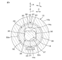
図2は、図1に示すステアリング装置1の操舵機構5の要部D2の断面図であり、図3に示すS2−S2断面を示す。図3は、図2のS3−S3断面の断面図である。
The steering device 1 according to the present embodiment is configured in the same manner with respect to the peripheral portions of both end portions 14b of the rack shaft 14 except for the first and second rack bushes 28 and 29 and the elastic member 31, and is similar to each other. About the structure, the same code | symbol is attached | subjected and description is abbreviate | omitted.
2 is a cross-sectional view of a main part D2 of the steering mechanism 5 of the steering device 1 shown in FIG. 1, and shows a cross section taken along S2-S2 shown in FIG. 3 is a cross-sectional view taken along a line S3-S3 in FIG.

ラックハウジング15の第1の端部15aは、保持孔32を有している。保持孔32は、円筒面をなす内周面32aと、この内周面32aの一端から径方向内方へ延びる側壁32bとを有している。また、内周面32aに凹部33が形成されている。
保持孔32の開口端に、ラックストッパ30が固定されている。ラックストッパ30は、環状をなし、ボールジョイントユニット26(図1参照)の一部と当接することにより、ラック軸14の軸方向Sに関してのラックハウジング15に対するラック軸14の移動範囲を規制する。
The first end 15 a of the rack housing 15 has a holding hole 32. The holding hole 32 has an inner peripheral surface 32a that forms a cylindrical surface, and a side wall 32b that extends radially inward from one end of the inner peripheral surface 32a. Moreover, the recessed part 33 is formed in the internal peripheral surface 32a.
A rack stopper 30 is fixed to the opening end of the holding hole 32. The rack stopper 30 has an annular shape and abuts against a part of the ball joint unit 26 (see FIG. 1), thereby restricting the range of movement of the rack shaft 14 relative to the rack housing 15 in the axial direction S of the rack shaft 14.

第1のラックブッシュ28は、ラック軸14の軸方向Sに関して、ラックストッパ30と側壁32bとの間に挟持されている。保持孔32の側壁32bにより軸方向Sの一方の向きへの第1のラックブッシュ28の移動が規制され、ラックストッパ30により軸方向Sの他方の向きへの第1のラックブッシュ28の移動が規制されている。
凹部33は、保持孔32の内周面32aの一部に所定深さで形成されていて、保持孔32の内側へ開放されている。凹部33は、ラック軸14の軸方向Sに関して、保持孔32の内周面32aの中央部に配置されている。また、ラック軸14の軸方向Sに沿って見たときに、凹部33とピニオン軸13とは、ラック軸14を挟んで、互いに反対側に配置されている。
The first rack bush 28 is sandwiched between the rack stopper 30 and the side wall 32b in the axial direction S of the rack shaft 14. The movement of the first rack bush 28 in one direction in the axial direction S is restricted by the side wall 32b of the holding hole 32, and the movement of the first rack bush 28 in the other direction in the axial direction S is restricted by the rack stopper 30. It is regulated.
The recess 33 is formed in a part of the inner peripheral surface 32 a of the holding hole 32 with a predetermined depth, and is open to the inside of the holding hole 32. The recess 33 is disposed at the center of the inner peripheral surface 32 a of the holding hole 32 with respect to the axial direction S of the rack shaft 14. Further, when viewed along the axial direction S of the rack shaft 14, the recess 33 and the pinion shaft 13 are disposed on opposite sides of the rack shaft 14.

凹部33内に弾性部材31が収容されている。凹部33の底面が、弾性部材31を受けて保持している。また、凹部33の側壁が、ラック軸14の周方向Tに関しての弾性部材31の移動を規制している。
弾性部材31は、弾性体としての合成樹脂材料により形成された板ばねからなる。この板ばねは、互いに反対側にある一対の面を有している。板ばねは、ラック軸14の軸方向Sから見たときに断面湾曲形状をなしている。一方の面が凸湾曲し、他方の面が凹湾曲している。凹湾曲している面の両端部が、第1のラックブッシュ28の外周面39に接続されていて、固定されている。凹湾曲している面の中央部が、対向する部分としての第1のラックブッシュ28との間に隙間を開けている。凸湾曲している面の中央部が、凹部33の底面に接続され、当接している。凸湾曲している面の両端部が、凹部33の側壁にともに当接している。なお、弾性部材31の向きが逆に配置されて、凸湾曲している面の中央部が第1のラックブッシュ28の外周面39に接続され、凹湾曲している面の両端部が凹部33の底面に接続されることも考えられる。
The elastic member 31 is accommodated in the recess 33. The bottom surface of the recess 33 receives and holds the elastic member 31. Further, the side wall of the recess 33 restricts the movement of the elastic member 31 in the circumferential direction T of the rack shaft 14.
The elastic member 31 is a leaf spring formed of a synthetic resin material as an elastic body. This leaf spring has a pair of surfaces on opposite sides. The leaf spring has a curved shape when viewed from the axial direction S of the rack shaft 14. One surface is convexly curved and the other surface is concavely curved. Both end portions of the concavely curved surface are connected to the outer peripheral surface 39 of the first rack bush 28 and fixed. A gap is formed between the center portion of the concavely curved surface and the first rack bush 28 as an opposing portion. The central portion of the convexly curved surface is connected to and abuts the bottom surface of the concave portion 33. Both end portions of the convexly curved surface are in contact with the side wall of the concave portion 33. In addition, the direction of the elastic member 31 is reversed, the central portion of the convexly curved surface is connected to the outer peripheral surface 39 of the first rack bush 28, and both end portions of the concavely curved surface are the concave portions 33. It is also conceivable that it is connected to the bottom surface.

弾性部材31は、湾曲の曲率半径が大きくなるような弾性曲げ変形を受けた状態で、凹部33の底面と第1のラックブッシュ28との間に介在している。これにより弾性部材31は、第1のラックブッシュ28を弾性的に押圧付勢しており、第1のラックブッシュ28を介してラック軸14を所定の付勢方向Fに付勢している。ここで、所定の付勢方向Fは、軸方向Sに直交する方向であってラック軸14とピニオン軸13とが互いに並ぶ方向であり、ラック軸14がピニオン軸13に向かって近づく方向である。   The elastic member 31 is interposed between the bottom surface of the recess 33 and the first rack bush 28 in a state where the elastic member 31 is subjected to an elastic bending deformation that increases the curvature radius of the curve. Accordingly, the elastic member 31 elastically presses and urges the first rack bush 28 and urges the rack shaft 14 in a predetermined urging direction F via the first rack bush 28. Here, the predetermined urging direction F is a direction orthogonal to the axial direction S, in which the rack shaft 14 and the pinion shaft 13 are aligned with each other, and the rack shaft 14 approaches the pinion shaft 13. .

凹部33に収容された弾性部材31は、第1のラックブッシュ28の周方向Tへの移動を規制するように、第1のラックブッシュ28と連結されている。具体的には、弾性部材31と第1のラックブッシュ28とは単一の部材としての合成樹脂部材により一体に形成されている。
第1のラックブッシュ28は、筒状をなしている。第1のラックブッシュ28の筒の中心軸線が、ラック軸14の軸方向Sに平行に配置されている。第1のラックブッシュ28は、摺動特性が優れた材料としての合成樹脂部材により形成されている。
The elastic member 31 accommodated in the recess 33 is connected to the first rack bush 28 so as to restrict the movement of the first rack bush 28 in the circumferential direction T. Specifically, the elastic member 31 and the first rack bush 28 are integrally formed of a synthetic resin member as a single member.
The first rack bush 28 has a cylindrical shape. The center axis of the cylinder of the first rack bush 28 is arranged in parallel to the axial direction S of the rack shaft 14. The first rack bush 28 is formed of a synthetic resin member as a material having excellent sliding characteristics.

第1のラックブッシュ28は、支持孔34を有している。この支持孔34をラック軸14が貫通している。支持孔34は、内周面35を有している。この内周面35が、ラック軸14の端部14bの上述の第1の部分を軸方向Sに摺動自在に支持している。
支持孔34の内周面35は、ラック軸14の移動を規制する一対の規制部36と、所定の付勢方向Fにラック軸14を押圧する押圧部37と、押圧部37に対向する対向部38とを有している。一対の規制部36と押圧部37と対向部38との端縁同士が互いに接続されることにより、内周面35が形成されている。また、一対の規制部36および押圧部37によって、ラック軸14が3点支持されている。
The first rack bush 28 has a support hole 34. The rack shaft 14 passes through the support hole 34. The support hole 34 has an inner peripheral surface 35. The inner peripheral surface 35 supports the first portion of the end portion 14b of the rack shaft 14 so as to be slidable in the axial direction S.
The inner peripheral surface 35 of the support hole 34 is a pair of restricting portions 36 that restrict the movement of the rack shaft 14, a pressing portion 37 that presses the rack shaft 14 in a predetermined biasing direction F, and an opposing surface that faces the pressing portion 37. Part 38. The inner peripheral surface 35 is formed by connecting edges of the pair of restricting portions 36, the pressing portion 37, and the facing portion 38 to each other. Further, the rack shaft 14 is supported at three points by the pair of regulating portions 36 and the pressing portion 37.

一対の規制部36は、付勢方向Fとは直交する方向Cとしてのラック軸14の径方向に、互いに対向している。一対の規制部36の間に、ラック軸14が配置されている。一対の規制部36は、上述の直交する方向Cについての両側へのラック軸14の移動を規制している。各規制部36は、所定の付勢方向Fと平行であり且つ軸方向Sに平行な平坦面により形成されていて、ラック軸14に線接触している。   The pair of restricting portions 36 oppose each other in the radial direction of the rack shaft 14 as the direction C orthogonal to the urging direction F. The rack shaft 14 is disposed between the pair of restricting portions 36. The pair of restricting portions 36 restricts the movement of the rack shaft 14 to both sides in the orthogonal direction C described above. Each restricting portion 36 is formed by a flat surface parallel to a predetermined biasing direction F and parallel to the axial direction S, and is in line contact with the rack shaft 14.

一対の規制部36同士の間隔は、第1のラックブッシュ28の部品単品の状態で、ラック軸14の外周面の直径と等しい距離か、この距離よりもわずかに小さくされていて、これにより、締めしろを付与された状態でラック軸14に接している。
押圧部37は、平坦面に形成されていて、ラック軸14に線接触している。押圧部37の平坦面は、所定の付勢方向Fに直交し且つ軸方向Sに平行な面からなる。ラック軸14の軸方向Sに垂直な断面において、押圧部37は、所定の付勢方向Fへの弾性部材31の付勢力を受けて、ラック軸14のラック歯14aの背面14cを押圧している。この背面14cは、ラック軸14の軸方向Sから見たときに、ラック歯14aとは径方向Rについて反対側にあり軸方向Sに延びる面であり、軸方向Sに関してラック歯14aが形成された部分と、ラック歯14aが形成されていない部分とのいずれにあってもよい。
The distance between the pair of restricting portions 36 is a distance equal to or slightly smaller than the diameter of the outer peripheral surface of the rack shaft 14 in the state of a single component of the first rack bush 28, The rack shaft 14 is in contact with a tightening margin.
The pressing portion 37 is formed on a flat surface and is in line contact with the rack shaft 14. The flat surface of the pressing portion 37 is a surface that is orthogonal to the predetermined biasing direction F and is parallel to the axial direction S. In a cross section perpendicular to the axial direction S of the rack shaft 14, the pressing portion 37 receives a biasing force of the elastic member 31 in a predetermined biasing direction F and presses the back surface 14 c of the rack teeth 14 a of the rack shaft 14. Yes. The rear surface 14c is a surface that is opposite to the rack tooth 14a in the radial direction R and extends in the axial direction S when viewed from the axial direction S of the rack shaft 14, and the rack teeth 14a are formed in the axial direction S. And the portion where the rack teeth 14a are not formed.

対向部38と押圧部37とは、所定の付勢方向Fに互いに対向している。対向部38は、凹湾曲面に形成されている。対向部38とラック軸14の外周面のラック歯14aとの間には、所定量の隙間40が開けられている。
第1のラックブッシュ28の外周面39と保持孔32の内周面32aとの間には、所定量の隙間が開けられているとともに、この隙間に環状のOリング41が介在している。このOリング41は、第1のラックブッシュ28を取り囲んで弾性圧縮変形されていて、第1のラックブッシュ28を介してラック軸14を弾性支持している。これにより、第1のラックブッシュ28は、ラック軸14の任意の径方向Rについて、保持孔32内で変位可能に支持されている。
The facing portion 38 and the pressing portion 37 face each other in a predetermined biasing direction F. The facing portion 38 is formed on a concave curved surface. A predetermined amount of gap 40 is formed between the facing portion 38 and the rack teeth 14 a on the outer peripheral surface of the rack shaft 14.
A predetermined amount of gap is formed between the outer peripheral surface 39 of the first rack bush 28 and the inner peripheral surface 32a of the holding hole 32, and an annular O-ring 41 is interposed in this gap. The O-ring 41 surrounds the first rack bush 28 and is elastically compressed and deformed, and elastically supports the rack shaft 14 via the first rack bush 28. Accordingly, the first rack bush 28 is supported so as to be displaceable in the holding hole 32 in an arbitrary radial direction R of the rack shaft 14.

例えば、第1のラックブッシュ28の外周面39に、複数、例えば2本の環状溝が形成されている。各環状溝は、所定深さで周方向Tに延びて、ラック軸14の軸方向Sに関して弾性部材31を避けた位置であって弾性部材31を挟んだ両側に配置されている。各環状溝にOリング41がそれぞれ嵌め入れられている。Oリング41は、弾性体としてのゴム部材や合成樹脂部材により無端状に形成されている。ラック軸14の径方向に関して、Oリング41が弾性圧縮変形を受けた状態で、保持孔32の内周面32aと第1のラックブッシュ28の外周面39との間に介在している。   For example, a plurality of, for example, two annular grooves are formed on the outer peripheral surface 39 of the first rack bush 28. Each annular groove extends in the circumferential direction T at a predetermined depth, and is disposed on both sides of the elastic member 31 at a position avoiding the elastic member 31 in the axial direction S of the rack shaft 14. An O-ring 41 is fitted in each annular groove. The O-ring 41 is formed endlessly by a rubber member or a synthetic resin member as an elastic body. With respect to the radial direction of the rack shaft 14, the O-ring 41 is interposed between the inner peripheral surface 32 a of the holding hole 32 and the outer peripheral surface 39 of the first rack bush 28 in a state of undergoing elastic compression deformation.

なお、Oリング41用の環状溝が、保持孔32の内周面32aに形成されていてもよい。また、第1のラックブッシュ28の外周面39と、保持孔32の内周面32aとに互いに対向して形成されてもよい。また、Oリング41は、少なくとも1つがあればよく、Oリング41に代えて、弾性体としてのゴム板を用いることも考えられる。
図1に戻って、ラックハウジング15の第2の端部15bは、保持孔32を有している。この保持孔32は、第2のラックブッシュ29を嵌合状態で保持し、凹部33を廃止されている。第2のラックブッシュ29は、弾性部材31の付勢がない点を除いて、第1のラックブッシュ28と同様に保持孔32に保持されている。
An annular groove for the O-ring 41 may be formed on the inner peripheral surface 32 a of the holding hole 32. Further, the outer peripheral surface 39 of the first rack bush 28 and the inner peripheral surface 32a of the holding hole 32 may be formed to face each other. Further, it is sufficient that at least one O-ring 41 is provided, and instead of the O-ring 41, a rubber plate as an elastic body may be used.
Returning to FIG. 1, the second end 15 b of the rack housing 15 has a holding hole 32. The holding hole 32 holds the second rack bush 29 in a fitted state, and the recess 33 is eliminated. The second rack bush 29 is held in the holding hole 32 similarly to the first rack bush 28 except that the elastic member 31 is not biased.

第2のラックブッシュ29は、ラック軸14の任意の径方向Rに関するラック軸14の端部14bの第2の部分の移動を所定量に規制している。第2のラックブッシュ29とラック軸14との間には、締め代が付与されていてもよいし、所定の隙間が設定されていてもよい。また、第2のラックブッシュ29は、第1のラックブッシュ28と同様にOリング41を介してラックハウジング15に弾性支持されているが、ラックハウジング15に固定することも考えられる。   The second rack bush 29 restricts the movement of the second portion of the end portion 14b of the rack shaft 14 with respect to the arbitrary radial direction R of the rack shaft 14 to a predetermined amount. A fastening allowance may be provided between the second rack bush 29 and the rack shaft 14, or a predetermined gap may be set. The second rack bush 29 is elastically supported by the rack housing 15 via the O-ring 41 in the same manner as the first rack bush 28, but may be fixed to the rack housing 15.

図1および図2を参照して、所定の付勢方向Fに関して、弾性部材31は、Oリング41の弾性反発力に抗しつつ、または、この弾性反発力と協働して、第1のラックブッシュ28を押圧し、ひいては、ラック軸14を押圧している。このとき、支点としての第2のラックブッシュ29がラック軸14の他方の端部14bを受けて、ラック軸14のラック歯14aとピニオン軸13のピニオン歯13aとが、互いにバックラッシを除去された状態で噛み合うようにされている。   With reference to FIGS. 1 and 2, the elastic member 31 resists the elastic repulsive force of the O-ring 41 or cooperates with the elastic repulsive force with respect to the predetermined urging direction F. The rack bush 28 is pressed, and consequently the rack shaft 14 is pressed. At this time, the second rack bush 29 as a fulcrum receives the other end 14b of the rack shaft 14, and the back teeth of the rack teeth 14a of the rack shaft 14 and the pinion teeth 13a of the pinion shaft 13 are removed from each other. It is designed to mesh with each other.

本実施形態では、ラックアンドピニオン式のステアリング装置1において、ラック軸14が挿通され、軸方向Sに関して第1および第2の端部15a,15bを有する筒状のラックハウジング15と、このラックハウジング15の第1および第2の端部15a,15bのうちピニオン軸13に相対的に近い第1の端部15aに保持され、ラック軸14の端部14bを軸方向Sに摺動自在に支持する支持孔34を有する第1のラックブッシュ28と、この第1のラックブッシュ28を介してラック軸14をピニオン軸13に向かう所定の付勢方向Fに付勢する弾性部材31とを備え、上記第1のラックブッシュ28は、ラックハウジング15によって所定の付勢方向Fに変位可能に支持されていることを特徴とする。   In the present embodiment, in the rack and pinion type steering apparatus 1, the rack shaft 14 is inserted, the cylindrical rack housing 15 having the first and second end portions 15 a and 15 b with respect to the axial direction S, and the rack housing Of the first and second end portions 15a and 15b, the first end portion 15a is relatively close to the pinion shaft 13, and the end portion 14b of the rack shaft 14 is slidably supported in the axial direction S. A first rack bush 28 having a support hole 34 to be supported, and an elastic member 31 that urges the rack shaft 14 in a predetermined urging direction F toward the pinion shaft 13 via the first rack bush 28. The first rack bush 28 is supported by the rack housing 15 so as to be displaceable in a predetermined urging direction F.

これにより、もともと必須の構成であるラックブッシュとしての第1のラックブッシュ28を介して、弾性部材31がラック軸14をピニオン軸13に向けて付勢し、これにより、ラック軸14とピニオン軸13との間のバックラッシを抑制して、異音の発生を抑制することができる。従来のサポートヨークを用いる複雑な構造のラック軸支持装置を廃止することができ、部品コスト、組立コストの低減を通じて製造コストを安くすることができる。   As a result, the elastic member 31 urges the rack shaft 14 toward the pinion shaft 13 via the first rack bush 28 as a rack bush, which is an essential configuration, and thereby the rack shaft 14 and the pinion shaft are urged. It is possible to suppress the backlash between the two and the generation of abnormal noise. The conventional rack shaft support device having a complicated structure using the support yoke can be abolished, and the manufacturing cost can be reduced by reducing the component cost and the assembly cost.

また、第1のラックブッシュ28は、ピニオン軸14に近い側にある第1の端部15aに配置されているので、ピニオン軸13に向けてラック軸14を効果的に付勢することができる。
また、第1のラックブッシュ28は、その中央部の支持孔34にラック軸14を挿通させているので、第1のラックブッシュ28が、所定の付勢方向Fに弾性部材31により付勢された状態で、上記所定の付勢方向Fにラックハウジング15により変位可能に保持されている場合であっても、中央部を挿通するラック軸14により第1のラックブッシュ28の姿勢が規制され、従来のサポートヨークに比べて、第1のラックブッシュ28の倒れやがたつきの発生が抑制される。ひいては、ラックハウジング15の保持孔32の内周面32aと第1のラックブッシュ28の外周面39との間の隙間を厳密に管理せずに済み、製造コストを安価にできる。
Further, since the first rack bush 28 is disposed at the first end portion 15a on the side close to the pinion shaft 14, the rack shaft 14 can be effectively urged toward the pinion shaft 13. .
Further, since the rack shaft 14 is inserted through the support hole 34 at the center of the first rack bush 28, the first rack bush 28 is urged by the elastic member 31 in a predetermined urging direction F. Even when the rack housing 15 is held so as to be displaceable in the predetermined urging direction F, the attitude of the first rack bush 28 is regulated by the rack shaft 14 inserted through the center portion, Compared with the conventional support yoke, the occurrence of the tilting and rattling of the first rack bush 28 is suppressed. As a result, it is not necessary to strictly manage the gap between the inner peripheral surface 32a of the holding hole 32 of the rack housing 15 and the outer peripheral surface 39 of the first rack bush 28, and the manufacturing cost can be reduced.

また、従来のラック軸支持装置を廃止するのに伴い、ラック軸14の軸方向Sの移動抵抗を低減することができる。
また、第1および第2のラックブッシュ28,29は、ラック軸14に摺動自在に接するので、ラック軸との間にボールを介在させる場合に比べて、構造を簡素化できる。
さらに、第1および第2のラックブッシュ28,29は、直交する方向Cについてのラック軸14の移動をともに規制している。これにより、ラック軸14の軸方向移動時に第1および第2のラックブッシュ28,29のがたつきが生じ難く、このがたつきに起因する異音の発生を抑制することができる。
Further, with the abolition of the conventional rack shaft support device, the movement resistance of the rack shaft 14 in the axial direction S can be reduced.
Further, since the first and second rack bushes 28 and 29 are slidably in contact with the rack shaft 14, the structure can be simplified as compared with the case where a ball is interposed between the first and second rack bushes 28 and 29.
Furthermore, the first and second rack bushes 28 and 29 both restrict the movement of the rack shaft 14 in the direction C perpendicular to each other. Thereby, when the rack shaft 14 is moved in the axial direction, the first and second rack bushes 28 and 29 are unlikely to rattle, and the occurrence of abnormal noise due to the rattling can be suppressed.

また、本実施形態では、ラックハウジング15は、第1のラックブッシュ28を保持する保持孔32を有し、保持孔32の内周面32aの一部に、弾性部材31を収容するための凹部33が形成されている。この場合、凹部33に収容された弾性部材31の付勢方向Fを規制することができる。また、凹部33の周囲にある内周面32aの部分32cが第1のラックブッシュ28を受けるので、第1のラックブッシュ28が弾性部材31を過度に変形させることを防止することができる。   In the present embodiment, the rack housing 15 has a holding hole 32 that holds the first rack bush 28, and a recess for accommodating the elastic member 31 in a part of the inner peripheral surface 32 a of the holding hole 32. 33 is formed. In this case, the urging direction F of the elastic member 31 accommodated in the recess 33 can be restricted. Further, since the portion 32c of the inner peripheral surface 32a around the recess 33 receives the first rack bush 28, the first rack bush 28 can be prevented from excessively deforming the elastic member 31.

また、第1のラックブッシュ28の支持孔34の内周面35は、所定の付勢方向Fと直交する方向Cへの、ラック軸14の移動を規制する一対の規制部36と、所定の付勢方向Fへの弾性部材の付勢力によりラック軸14のラック歯14aの背面14cを押圧する押圧部37とを含み、これら一対の規制部36および押圧部37によって、ラック軸14が3点支持されている。この場合、第1のラックブッシュ28は、付勢方向Fおよび上述の直交する方向Cに関してのラック軸14のがたつきを確実に防止できる。   The inner peripheral surface 35 of the support hole 34 of the first rack bush 28 has a pair of restricting portions 36 that restrict the movement of the rack shaft 14 in the direction C perpendicular to the predetermined biasing direction F, and a predetermined amount. And a pressing portion 37 that presses the back surface 14c of the rack tooth 14a of the rack shaft 14 by the biasing force of the elastic member in the biasing direction F. The rack shaft 14 has three points by the pair of regulating portions 36 and the pressing portion 37. It is supported. In this case, the first rack bush 28 can reliably prevent the rack shaft 14 from rattling in the urging direction F and the orthogonal direction C described above.

また、一対の規制部36のそれぞれは、所定の付勢方向Fと平行な平坦面を含んでいる。この場合、規制部36によって所定の付勢方向Fへのラック軸14の移動をスムーズに案内することができる。また、規制部36は、弾性部材31による付勢力を受けずに済むので、摩耗が生じ難い結果、ラック軸14をがたつきなく保持するのに好ましい。
また、第1のラックブッシュ28の支持孔34の内周面35は、押圧部37と対向する対向部38を含む。この対向部38とラック軸14との間に所定の隙間40が設けられている。この場合、軸方向Sに関してのラック軸14の移動抵抗の低減に寄与する。また、ラック軸14を第1のラックブッシュ28に容易に通すことができるので、ステアリング装置1を組立易い。
Further, each of the pair of restricting portions 36 includes a flat surface parallel to the predetermined biasing direction F. In this case, the movement of the rack shaft 14 in the predetermined urging direction F can be smoothly guided by the restricting portion 36. Further, since the restricting portion 36 does not need to receive the urging force by the elastic member 31, it is preferable to hold the rack shaft 14 without rattling as a result of being hard to be worn.
The inner peripheral surface 35 of the support hole 34 of the first rack bush 28 includes a facing portion 38 that faces the pressing portion 37. A predetermined gap 40 is provided between the facing portion 38 and the rack shaft 14. In this case, it contributes to the reduction of the movement resistance of the rack shaft 14 in the axial direction S. Moreover, since the rack shaft 14 can be easily passed through the first rack bush 28, the steering device 1 can be easily assembled.

また、凹部33に収容された弾性部材31は、周方向Tへの第1のラックブッシュ28の移動を規制するように、第1のラックブッシュ28と連結されている。この場合、弾性部材31は第1のラックブッシュ28の回り止めとしても兼用されるので、構造が簡素化される。ここで、弾性部材31と第1のラックブッシュ28との連結としては、これらを単一の部材により一体に形成すること、これらを複数の部材により一体に形成すること、これらを互いに固定して一体化することのいずれでもよい。   Further, the elastic member 31 accommodated in the recess 33 is connected to the first rack bush 28 so as to restrict the movement of the first rack bush 28 in the circumferential direction T. In this case, since the elastic member 31 is also used as a detent for the first rack bush 28, the structure is simplified. Here, as the connection between the elastic member 31 and the first rack bush 28, these are integrally formed by a single member, these are integrally formed by a plurality of members, and they are fixed to each other. Either of them may be integrated.

また、保持孔32の内周面32aと、第1のラックブッシュ28の外周面39との間に、環状のOリング41が介在し、このOリング41によって、ラック軸14が弾性支持されている。この場合、付勢方向Fに関しては、弾性部材31が第1のラックブッシュ28を介してラック軸14を付勢することができる。しかも、直交する方向Cに関しては、Oリング41の弾性反発力により第1のラックブッシュ28のがたつきの発生を抑制することができ、さらに、これらの効果を簡素な構造で達成することができる。   An annular O-ring 41 is interposed between the inner peripheral surface 32 a of the holding hole 32 and the outer peripheral surface 39 of the first rack bush 28, and the rack shaft 14 is elastically supported by the O-ring 41. Yes. In this case, with respect to the urging direction F, the elastic member 31 can urge the rack shaft 14 via the first rack bush 28. In addition, with respect to the direction C orthogonal, the occurrence of rattling of the first rack bush 28 can be suppressed by the elastic repulsive force of the O-ring 41, and further, these effects can be achieved with a simple structure. .

このようにがたつきの抑制が、第1のラックブッシュ28を弾性支持することにより達成されるので、ラックハウジング15の保持孔32の内周面32aと第1のラックブッシュ28との隙間を、所定の微小量に管理せずに済み、製造コストを安価にできる。
また、本実施形態について、以下のような変形例を考えることができる。以下の説明では、上述の実施形態と異なる点を中心に説明し、同様の構成については同じ符号を付して説明を省略する。
In this way, suppression of rattling is achieved by elastically supporting the first rack bush 28, so that the clearance between the inner peripheral surface 32a of the holding hole 32 of the rack housing 15 and the first rack bush 28 is It is not necessary to manage to a predetermined minute amount, and the manufacturing cost can be reduced.
Moreover, the following modifications can be considered about this embodiment. In the following description, differences from the above-described embodiment will be mainly described, and the same components are denoted by the same reference numerals and description thereof is omitted.

図4は、本発明の第2の実施形態のステアリング装置の要部の断面図である。図4を参照して、本実施形態では、弾性部材31と第1のラックブッシュ28とは、互いに別体に形成されていて、互いに分離可能とされている。この場合、弾性部材31および第1のラックブッシュ28を、それぞれに最適な部材によりそれぞれ形成することができる。
また、弾性部材31は、凹部33の底面に2箇所で受けられていて、第1のラックブッシュ28の外周面39に1箇所で接している。なお、弾性部材31を、逆向きにし第1の実施形態のように配置してもよい。
FIG. 4 is a cross-sectional view of a main part of the steering device according to the second embodiment of the present invention. With reference to FIG. 4, in this embodiment, the elastic member 31 and the first rack bush 28 are formed separately from each other and can be separated from each other. In this case, the elastic member 31 and the first rack bush 28 can be formed of members that are optimum for each.
The elastic member 31 is received at two locations on the bottom surface of the recess 33 and is in contact with the outer peripheral surface 39 of the first rack bush 28 at one location. The elastic member 31 may be disposed in the reverse direction as in the first embodiment.

また、保持孔32および第1のラックブッシュ28は、互いに係合することにより相対回動を規制する回り止め部としての一対の係合部42,43を有している。係合部42は、ラックハウジング15に形成された起伏部としての凹部からなる。係合部43は、第1のラックブッシュ28に形成された起伏部としての凸部からなる。係合部42,43が互いに凹凸係合することにより、第1のラックブッシュ28は第1の実施形態と同様に配置され、例えば軸方向Sに沿って見たときに、押圧部37がラック軸14を挟んでピニオン軸13とは反対側に配置されるようになっている。なお、係合部42,43の凹凸関係は、逆であってもよい。   Further, the holding hole 32 and the first rack bush 28 have a pair of engaging portions 42 and 43 as rotation stoppers that restrict relative rotation by engaging with each other. The engaging portion 42 is formed of a concave portion as a undulating portion formed in the rack housing 15. The engaging portion 43 is composed of a convex portion as an undulating portion formed on the first rack bush 28. When the engaging portions 42 and 43 engage with each other in a concave-convex manner, the first rack bush 28 is arranged in the same manner as in the first embodiment. For example, when viewed along the axial direction S, the pressing portion 37 is mounted on the rack. The pinion shaft 13 is disposed on the opposite side of the shaft 14. In addition, the uneven | corrugated relationship of the engaging parts 42 and 43 may be reverse.

図5は、本発明の第3の実施形態のステアリング装置1の要部の断面図である。図5を参照して、第1のラックブッシュ28の支持孔34の内周面35は、複数の凸部44を有している。これ以外の点では、本実施形態は、第1の実施形態と同様である。
内周面35は、円筒面からなる湾曲部45と、この湾曲部45から径方向内方に突出した上述の凸部44とを有している。第1のラックブッシュ28の支持孔34の内周面35の一対の規制部36および押圧部37は、3つの凸部44の先端に配置されている。各凸部44の先端は、平坦面に形成されている。これらの平坦面は、第1の実施形態における一対の規制部36および押圧部37の対応する平坦面と同様に形成されている。また、各凸部44は、軸方向Sに関して第1のラックブッシュ28の全長にわたって延びていて、断面形状は、軸方向Sに関して一定に形成されている。
FIG. 5 is a cross-sectional view of a main part of the steering device 1 according to the third embodiment of the present invention. Referring to FIG. 5, the inner peripheral surface 35 of the support hole 34 of the first rack bush 28 has a plurality of convex portions 44. In other respects, the present embodiment is the same as the first embodiment.
The inner peripheral surface 35 has a curved portion 45 formed of a cylindrical surface, and the above-described convex portion 44 that protrudes radially inward from the curved portion 45. A pair of restricting portions 36 and pressing portions 37 on the inner peripheral surface 35 of the support hole 34 of the first rack bush 28 are arranged at the tips of the three convex portions 44. The tip of each convex portion 44 is formed on a flat surface. These flat surfaces are formed in the same manner as the corresponding flat surfaces of the pair of restricting portions 36 and pressing portions 37 in the first embodiment. Further, each convex portion 44 extends over the entire length of the first rack bush 28 in the axial direction S, and the cross-sectional shape is formed constant with respect to the axial direction S.

なお、凸部44は、内周面35に一体に形成されていてもよいし、内周面35に別体で形成されて固定されていてもよい。また、一対の規制部36および押圧部37の一部に対応して凸部44を設けてもよい。また、第2の実施形態の第1のラックブッシュ28の内周面35に凸部44を設けてもよい。
このように第1のラックブッシュ28の支持孔34の内周面35は、一対の規制部36および押圧部37の少なくとも1つに対応して凸部44を設けている。この場合、第1のラックブッシュ28とラック軸14との接触面積を低減して、軸方向Sに関してのラック軸14の移動抵抗を低減することができる。
Note that the convex portion 44 may be formed integrally with the inner peripheral surface 35, or may be formed separately and fixed to the inner peripheral surface 35. Further, the convex portion 44 may be provided corresponding to a part of the pair of regulating portions 36 and the pressing portion 37. Moreover, you may provide the convex part 44 in the internal peripheral surface 35 of the 1st rack bush 28 of 2nd Embodiment.
As described above, the inner peripheral surface 35 of the support hole 34 of the first rack bush 28 is provided with a convex portion 44 corresponding to at least one of the pair of restricting portions 36 and the pressing portion 37. In this case, the contact area between the first rack bush 28 and the rack shaft 14 can be reduced, and the movement resistance of the rack shaft 14 in the axial direction S can be reduced.

また、上述の各実施形態において、第1のラックブッシュ28が弾性支持されずに所定の付勢方向Fに変位自在に保持される場合、隙間40が設けられずに対向部38がラック軸14に接する場合、一対の規制部36および押圧部37の少なくとも一つが凸湾曲面または凹湾曲面からなる場合、弾性部材31が凹部33のない保持孔32内に保持されている場合も考えられる。その他、特許請求の範囲に記載された事項の範囲で種々の設計変更を施すことが可能である。   In each of the above-described embodiments, when the first rack bush 28 is not elastically supported and is held so as to be displaceable in a predetermined urging direction F, the gap 38 is not provided, and the facing portion 38 is provided with the rack shaft 14. When at least one of the pair of regulating portions 36 and the pressing portion 37 is formed of a convex curved surface or a concave curved surface, the elastic member 31 may be held in the holding hole 32 without the concave portion 33. In addition, various design changes can be made within the scope of matters described in the claims.

本発明の第1の実施形態のステアリング装置の概略構成の側面図である。It is a side view of schematic structure of the steering device of a 1st embodiment of the present invention. 図1に示すステアリング装置の要部の断面図であり、図3のS2−S2断面を示す。It is sectional drawing of the principal part of the steering apparatus shown in FIG. 1, and shows the S2-S2 cross section of FIG. 図2のS3−S3断面の断面図である。It is sectional drawing of the S3-S3 cross section of FIG. 本発明の第2の実施形態のステアリング装置の要部の断面図であり、図3の断面に相当する。It is sectional drawing of the principal part of the steering device of the 2nd Embodiment of this invention, and is equivalent to the cross section of FIG. 本発明の第3の実施形態のステアリング装置の要部の断面図であり、図3の断面に相当する。It is sectional drawing of the principal part of the steering device of the 3rd Embodiment of this invention, and is equivalent to the cross section of FIG.

符号の説明Explanation of symbols

1…ステアリング装置、13…ピニオン軸、14…ラック軸、14a…ラック歯、14b…(ラック軸の)端部、14c…ラック歯の背面、15…ラックハウジング(ハウジング)、15a…第1の端部、15b…第2の端部、28…第1のラックブッシュ(ラックブッシュ)、31…弾性部材、32…保持孔、32a…(保持孔の)内周面、33…凹部、34…支持孔、35…(支持孔の)内周面、36…規制部、37…押圧部、38…対向部、39…(第1のラックブッシュの)外周面、40…隙間、41…Oリング、44…凸部、C…直交する方向、F…付勢方向、S…軸方向、T…周方向   DESCRIPTION OF SYMBOLS 1 ... Steering device, 13 ... Pinion shaft, 14 ... Rack shaft, 14a ... Rack tooth, 14b ... End of (rack shaft), 14c ... Back surface of rack tooth, 15 ... Rack housing (housing), 15a ... First End portion, 15b ... second end portion, 28 ... first rack bush (rack bush), 31 ... elastic member, 32 ... holding hole, 32a ... inner peripheral surface, 33 ... recessed portion, 34 ... Support hole, 35 ... inner peripheral surface of (support hole), 36 ... regulating portion, 37 ... pressing portion, 38 ... opposing portion, 39 ... outer peripheral surface of (first rack bush), 40 ... gap, 41 ... O-ring 44: convex portion, C: orthogonal direction, F: biasing direction, S: axial direction, T: circumferential direction

Claims (6)

ラックアンドピニオン式のステアリング装置において、
ラック軸が挿通され、軸方向に関して第1および第2の端部を有する筒状のハウジングと、
このハウジングの第1および第2の端部のうちピニオン軸に相対的に近い第1の端部に保持され、ラック軸の端部を軸方向に摺動自在に支持する支持孔を有するラックブッシュと、
このラックブッシュと連結されて一体化されていて、このラックブッシュの外周面から突出しており、このラックブッシュを介してラック軸をピニオン軸に向かう所定の付勢方向に付勢する弾性部材とを備え、
上記ラックブッシュは、ハウジングによって上記所定の付勢方向に変位可能に支持されていて、
上記ハウジングは、ラックブッシュを保持する保持孔を有し、保持孔の内周面の一部に、上記弾性部材を収容するための凹部が形成されていて、
上記凹部に収容された弾性部材は、上記凹部によって弾性的に位置決めされた状態で、ラックブッシュの周方向への移動を弾性的に規制することを特徴とするステアリング装置。
In a rack and pinion type steering device,
A cylindrical housing having a rack shaft inserted therein and having first and second ends in the axial direction;
A rack bush having a support hole that is held by a first end relatively close to the pinion shaft among the first and second ends of the housing and supports the end of the rack shaft so as to be slidable in the axial direction. When,
An elastic member that is connected and integrated with the rack bush, protrudes from the outer peripheral surface of the rack bush, and urges the rack shaft in a predetermined urging direction toward the pinion shaft via the rack bush. Prepared,
The rack bush is supported by a housing so as to be displaceable in the predetermined urging direction ,
The housing has a holding hole for holding the rack bush, and a recess for accommodating the elastic member is formed in a part of the inner peripheral surface of the holding hole,
The steering device according to claim 1, wherein the elastic member accommodated in the concave portion elastically restricts the movement of the rack bush in the circumferential direction while being elastically positioned by the concave portion .
請求項1において、上記ラックブッシュの支持孔の内周面は、上記所定の付勢方向と直交する方向への、ラック軸の移動を規制する一対の規制部と、上記所定の付勢方向への弾性部材の付勢力によりラック軸のラック歯の背面を押圧する押圧部とを含み、これら一対の規制部および押圧部によって、ラック軸が3点支持されていることを特徴とするステアリング装置。 Oite to claim 1, the inner peripheral surface of the supporting hole of the rack bush, in the direction perpendicular to the predetermined biasing direction, a pair of restricting portions for restricting the movement of the rack shaft, the predetermined force of the biasing And a pressing portion that presses the back surface of the rack tooth of the rack shaft by the urging force of the elastic member in the direction, and the steering shaft is supported at three points by the pair of restriction portions and the pressing portion. apparatus. 請求項において、上記一対の規制部のそれぞれは、上記所定の付勢方向と平行な平坦面を含むことを特徴とするステアリング装置。 3. The steering apparatus according to claim 2, wherein each of the pair of restricting portions includes a flat surface parallel to the predetermined urging direction. 請求項において、上記ラックブッシュの支持孔の内周面は、上記一対の規制部および押圧部の少なくとも1つに対応して凸部を設けていることを特徴とするステアリング装置。 3. The steering apparatus according to claim 2, wherein an inner peripheral surface of the support hole of the rack bush is provided with a convex portion corresponding to at least one of the pair of restricting portions and pressing portions. 請求項からの何れか1項において、上記ラックブッシュの支持孔の内周面は、上記押圧部と対向する対向部を含み、この対向部とラック軸との間に所定の隙間が設けられていることを特徴とするステアリング装置。 In any one of claims 2 to 4, the inner peripheral surface of the supporting hole of the rack bushing includes a facing portion opposed to the pressing portion, a predetermined gap between the opposing portion and the rack shaft is provided A steering apparatus characterized by being provided. 請求項からの何れか1項において、上記保持孔の内周面と、ラックブッシュの外周面との間に、環状のOリングが介在し、このOリングによって、ラック軸が弾性支持されていることを特徴とするステアリング装置。 In any one of claims 1 to 5, and the inner peripheral surface of the holding hole, between the outer peripheral surface of the rack bush, an annular O-ring is interposed, by the O-ring, the rack shaft is elastically supported A steering device characterized by that.
JP2006254918A 2006-09-20 2006-09-20 Steering device Expired - Fee Related JP5062465B2 (en)

Priority Applications (1)

Application Number Priority Date Filing Date Title
JP2006254918A JP5062465B2 (en) 2006-09-20 2006-09-20 Steering device

Applications Claiming Priority (1)

Application Number Priority Date Filing Date Title
JP2006254918A JP5062465B2 (en) 2006-09-20 2006-09-20 Steering device

Publications (2)

Publication Number Publication Date
JP2008074218A JP2008074218A (en) 2008-04-03
JP5062465B2 true JP5062465B2 (en) 2012-10-31

Family

ID=39346730

Family Applications (1)

Application Number Title Priority Date Filing Date
JP2006254918A Expired - Fee Related JP5062465B2 (en) 2006-09-20 2006-09-20 Steering device

Country Status (1)

Country Link
JP (1) JP5062465B2 (en)

Families Citing this family (9)

* Cited by examiner, † Cited by third party
Publication number Priority date Publication date Assignee Title
JP5179232B2 (en) 2008-03-21 2013-04-10 株式会社マキタ Tabletop cutting machine
JP5316125B2 (en) * 2009-03-17 2013-10-16 トヨタ自動車株式会社 Rack and pinion steering system
CN103029744B (en) * 2011-10-05 2017-09-12 株式会社捷太格特 Rack pinion formula transfer, its assemble method and bushing
JP2013079024A (en) * 2011-10-05 2013-05-02 Jtekt Corp Bush for rack shaft and steering device of rack-and-pinion type
JP5787159B2 (en) * 2011-10-05 2015-09-30 株式会社ジェイテクト Rack and pinion type steering device and method for assembling the device
JP6572624B2 (en) * 2015-05-20 2019-09-11 オイレス工業株式会社 Sliding bearing and bearing mechanism including the same
JP7324607B2 (en) * 2019-04-15 2023-08-10 マツダ株式会社 steering device
CN112319598B (en) * 2020-11-18 2021-11-23 浙江万洋汽车配件有限公司 Automobile steering device and steering device mounting mechanism
CN113847339A (en) * 2021-09-24 2021-12-28 中汽创智科技有限公司 Bushing and power steering system

Family Cites Families (3)

* Cited by examiner, † Cited by third party
Publication number Priority date Publication date Assignee Title
JPS5173425U (en) * 1974-12-05 1976-06-09
JPS5754459Y2 (en) * 1977-10-27 1982-11-25
JP2007076513A (en) * 2005-09-14 2007-03-29 Jtekt Corp Steering device

Also Published As

Publication number Publication date
JP2008074218A (en) 2008-04-03

Similar Documents

Publication Publication Date Title
JP5062465B2 (en) Steering device
JP6020893B2 (en) Electric power steering device
US8381868B2 (en) Electric power steering system
US9003909B2 (en) Rack bar supporting device of vehicle steering apparatus
US20080022796A1 (en) Steering apparatus equipped with ring type support yoke
JP4052218B2 (en) Electric power steering device
JP3763347B2 (en) Electric steering device
JP2012245810A (en) Rack shaft supporting device and vehicle steering device
JP3658683B2 (en) Electric steering device
JP5062467B2 (en) Steering device
JP3788576B2 (en) Electric power steering device
JP5878064B2 (en) Electric power steering device
US11965582B2 (en) Worm reducer and electric assist device
JP2008265550A (en) Electric power steering device
JP2012086799A (en) Electric power steering device
JP2007203947A (en) Worm reduction gear for electric power steering device, and electric power steering device with the worm reduction gear built therein
JP2013210005A (en) Electric power steering device
EP1970290B1 (en) Center take-off rack-and-pinion steering apparatus
JP2008074260A (en) Center take-off type steering device
JP4622638B2 (en) Rack and pinion type steering gear
JP4930771B2 (en) Electric power steering device
JP2014136437A (en) Rack pinion type steering device
JP4085802B2 (en) Electric power steering device
JP5392559B2 (en) Rack shaft support device
CN111801265B (en) Steering device

Legal Events

Date Code Title Description
A621 Written request for application examination

Free format text: JAPANESE INTERMEDIATE CODE: A621

Effective date: 20090825

A131 Notification of reasons for refusal

Free format text: JAPANESE INTERMEDIATE CODE: A131

Effective date: 20120426

A521 Written amendment

Free format text: JAPANESE INTERMEDIATE CODE: A523

Effective date: 20120606

TRDD Decision of grant or rejection written
A01 Written decision to grant a patent or to grant a registration (utility model)

Free format text: JAPANESE INTERMEDIATE CODE: A01

Effective date: 20120712

A01 Written decision to grant a patent or to grant a registration (utility model)

Free format text: JAPANESE INTERMEDIATE CODE: A01

A61 First payment of annual fees (during grant procedure)

Free format text: JAPANESE INTERMEDIATE CODE: A61

Effective date: 20120725

R150 Certificate of patent or registration of utility model

Free format text: JAPANESE INTERMEDIATE CODE: R150

FPAY Renewal fee payment (event date is renewal date of database)

Free format text: PAYMENT UNTIL: 20150817

Year of fee payment: 3

LAPS Cancellation because of no payment of annual fees