EP1451557B1 - Regensensor, insbesondere für ein kraftfahrzeug - Google Patents
Regensensor, insbesondere für ein kraftfahrzeug Download PDFInfo
- Publication number
- EP1451557B1 EP1451557B1 EP02774382A EP02774382A EP1451557B1 EP 1451557 B1 EP1451557 B1 EP 1451557B1 EP 02774382 A EP02774382 A EP 02774382A EP 02774382 A EP02774382 A EP 02774382A EP 1451557 B1 EP1451557 B1 EP 1451557B1
- Authority
- EP
- European Patent Office
- Prior art keywords
- rain sensor
- transmitter
- radiation
- sensor according
- per cent
- Prior art date
- Legal status (The legal status is an assumption and is not a legal conclusion. Google has not performed a legal analysis and makes no representation as to the accuracy of the status listed.)
- Expired - Lifetime
Links
Images

Classifications
-
- B—PERFORMING OPERATIONS; TRANSPORTING
- B60—VEHICLES IN GENERAL
- B60S—SERVICING, CLEANING, REPAIRING, SUPPORTING, LIFTING, OR MANOEUVRING OF VEHICLES, NOT OTHERWISE PROVIDED FOR
- B60S1/00—Cleaning of vehicles
- B60S1/02—Cleaning windscreens, windows or optical devices
- B60S1/04—Wipers or the like, e.g. scrapers
- B60S1/06—Wipers or the like, e.g. scrapers characterised by the drive
- B60S1/08—Wipers or the like, e.g. scrapers characterised by the drive electrically driven
- B60S1/0818—Wipers or the like, e.g. scrapers characterised by the drive electrically driven including control systems responsive to external conditions, e.g. by detection of moisture, dirt or the like
- B60S1/0822—Wipers or the like, e.g. scrapers characterised by the drive electrically driven including control systems responsive to external conditions, e.g. by detection of moisture, dirt or the like characterized by the arrangement or type of detection means
-
- B—PERFORMING OPERATIONS; TRANSPORTING
- B60—VEHICLES IN GENERAL
- B60S—SERVICING, CLEANING, REPAIRING, SUPPORTING, LIFTING, OR MANOEUVRING OF VEHICLES, NOT OTHERWISE PROVIDED FOR
- B60S1/00—Cleaning of vehicles
- B60S1/02—Cleaning windscreens, windows or optical devices
- B60S1/04—Wipers or the like, e.g. scrapers
- B60S1/06—Wipers or the like, e.g. scrapers characterised by the drive
- B60S1/08—Wipers or the like, e.g. scrapers characterised by the drive electrically driven
- B60S1/0818—Wipers or the like, e.g. scrapers characterised by the drive electrically driven including control systems responsive to external conditions, e.g. by detection of moisture, dirt or the like
- B60S1/0822—Wipers or the like, e.g. scrapers characterised by the drive electrically driven including control systems responsive to external conditions, e.g. by detection of moisture, dirt or the like characterized by the arrangement or type of detection means
- B60S1/0833—Optical rain sensor
- B60S1/0837—Optical rain sensor with a particular arrangement of the optical elements
Definitions
- the invention relates to a rain sensor according to the preamble of the independent claim.
- the diffractive elements are formed as volume phase holograms, which are incorporated in films of photopolymers.
- EP 0893317 describes a rain sensor with a diffractive element on which radiation is generated minus the first order.
- the rain sensor according to the invention with the features of the main claim has the advantage that the line-like structure of the diffractive element makes this cheaper and a wider range of materials can be applied. Furthermore, this improves, for example, the environmental properties. In addition, larger sensitive areas can be provided, whereby the response of the sensor unit is improved.
- the element diffracts the radiation into a first and a minus first order. In this way, two sensitive surfaces are achieved with only one transmitter, without having to increase the radiation intensity. As a result, further costs can be saved and the susceptibility to interference can be further reduced.
- a particularly good signal-to-noise ratio of the receiver signal is achieved in that the element has focusing properties.
- a particularly compact sensor is advantageously obtained if a further element is provided, which is partially designed as a retroreflector.
- the receiver can be placed in the vicinity of the transmitter or the transmitter can be used simultaneously as a receiver.
- At least one element and / or another element is formed as a multilayer structure, even more complex beam paths can be represented in a simple manner.
- an element has a plurality of structures that are superimposed in a layer.
- the elements or the further elements are arranged on the window of the motor vehicle. It is particularly advantageous if the diffraction efficiency of an element from 20 to 80%, in particular from 40 to 80%, preferably between 60 and 80%.
- Particularly good signals can be represented by the fact that the diffraction efficiency of the element is less than 100%, in particular less than 90, preferably less than 85%.
- this has more receivers than transmitters, since the transmitters are more expensive than the receivers.
- a rain sensor 10 is shown in a schematic cross-sectional view.
- This consists essentially of a housing 12 in which a printed circuit board 14 is arranged.
- the printed circuit board 14 carries a transmitter 16 and a receiver 18, which are formed as semiconductor devices in SMD technology.
- the housing 12 is seated on a disc 20, for example, the windshield of a motor vehicle and is mounted on it. This can be done for example by gluing, but also holding elements such as grooves or noses, which are arranged on or in the disc 20 and cooperate with fastening elements of the housing 12, are possible.
- diffractive elements 22a, 22b are glued, which consist of a film which is provided with a holographic line grid.
- One of the diffractive elements 22a is disposed in the region on the disk 20 in which the radiation of the transmitter 16 directly impinges on the disk 20.
- the film 22a is in this case designed such that it couples the radiation of the transmitter 16 in the disc 20 in such a way that the radiation at the rain sensor 10 remote from the clean and dry glass-air interface is totally reflected.
- the second diffractive element 22b is arranged at the location of the disk 20 at which the radiation of the transmitter 16 exits the disk 20 after total reflection.
- the line grid is chosen such that the totally reflected radiation is directed to the receiver 18, in particular focused.
- FIG. 2 an embodiment of the invention is shown.
- a transmitter 16 and two receivers 18 are arranged on the circuit board 14 here.
- the diffractive element 22a is arranged on the disk 20 with a line grid.
- the line grid is in turn designed such that the radiation of the transmitter 16 in the 1st and -1. Diffraction order is directed.
- the further diffractive elements 22b are arranged in the region of the receivers 18, such that the light from the 1st or -1. Diffraction order is directed to the receiver 18.
- the element 22a also cross-shaped measuring sections can be realized ( Fig. 7 )
- the diffractive element 22a is designed as a hologram foil with a line grid in such a way that the radiation radiating from the transmitter 16 perpendicular to the hologram foil is diffracted into the first order 24 and the minus first order 26.
- This effect of grating diffraction is well known in physics and described in numerous textbooks.
- First and minus first diffraction order have the same intensity. In the transmission direction, ie viewed in a straight line from the transmitter 16, there is the zeroth order, into which optionally no intensity can flow.
- the diffractive element 22b is designed such that only the light of the first order is conducted to the receivers 18 and the other orders, ie the minus first order or higher orders, are masked out. This is possible, for example, by the use of blazed gratings or so-called holographic lenses.
- the diffractive elements 22a, 22b may moreover have particular focusing properties, for example to transform the divergent cone-shaped beam of the transmitter 16 into one of cylindrical cross-section.
- the minus first order 26 may be divergent and will also be used as useful radiation by means of suitable further measures.
- the diffractive element 22a here consists of a superimposition of two mutually rotated by 180 degrees against each other diffracted structures, each of which predominantly bends to the first order.
- Both structures are superimposed in one layer. This can be achieved for example by double exposure of a hologram.
- these two structures can also be produced in separate layers and subsequently laminated, for example, to one another. This results in two diffracted in the opposite direction, focusing in the desired manner sub-beams of the 1st order. The also present rays of the minus first order are not exploited here.
- FIG. 6 an arrangement of diffractive elements 22a, 22b is shown.
- the path of the radiation of the transmitter 16 is shown schematically by the arrows.
- the central diffractive element 22a is arranged in the region of the transmitter 16 (not shown here) and diffracts the radiation in the first order via the non-drawn total glass-air interface to the outer receivers 18.
- FIG. 7 is a variation of in FIG. 6 shown arrangement shown.
- five diffractive elements 22 are shown.
- Four of these five diffractive elements 22a, 22b are arranged in the form of a square, in the center of which the fifth diffractive element 22a is arranged.
- the transmitter (not shown) is arranged, which conducts the radiation into the four outer diffractive elements 22b.
- the outer, arranged in the region of the receiver 18 diffractive elements 22b can of course also be arranged in the form of a rectangle, in the shape of a rhombus, but also in the form of a triangle or other geometric shape.
- the central diffractive element 22a of the transmitter 16 however, as many line structures are superimposed as there are receivers 18.
- the elements 22b can also be embodied as a retroreflector here and radiate the radiation back into the region of the transmitter, where the receiver 18 is then arranged.
- the elements 22b may also direct the radiation toward a common receiver 18, such that, for example, two juxtaposed elements 22b direct the radiation to a common receiver 18.
Landscapes
- Engineering & Computer Science (AREA)
- Automation & Control Theory (AREA)
- Mechanical Engineering (AREA)
- Investigating Or Analysing Materials By Optical Means (AREA)
Description
- Die Erfindung betrifft einen Regensensor nach Gattung des unabhängigen Anspruchs.
- Es sind schon zahlreiche Regensensoren, beispielsweise aus der
DE 197 01 258 bekannt, bei denen die Strahlung eines Senders mittels eines holografisch ausgebildeten, diffraktiven Elementes in die Scheibe eines Kraftfahrzeuges eingekoppelt, auf der Außenseite der Scheibe totalreflektiert, und mittels eines weiteren diffraktiven Elementes auf einen Empfänger gerichtet oder fokussiert wird. Bei derartigen Sensoren sind die diffraktiven Elemente als Volumenphasenhologramme ausgebildet, die in Folien aus Fotopolymeren eingebracht sind. -
EP 0893317 beschreibt einen Regensensor mit einen diffraktiven Element, an dem Strahlung minus erster Ordnung erzeugt wird. - Derartige Folien sind aufwändig zu fertigen, teuer in der Herstellung und problematisch in ihren Umwelteigenschaften.
- Der erfindungsgemäße Regensensor mit den Merkmalen des Hauptanspruchs hat den Vorteil, dass durch die linienartige Struktur des diffraktiven Elementes dieses kostengünstiger herzustellen ist und ein breiteres Materialspektrum angewendet werden kann. Weiterhin werden dadurch beispielsweise die Umwelteigenschaften verbessert. Darüber hinaus können größere sensitive Flächen vorgesehen werden, wodurch das Ansprechverhalten der Sensoreinheit verbessert wird.
- Durch die in den Unteransprüchen aufgeführten Maßnahmen ergeben sich vorteilhafte Weiterbildungen und Verbesserungen der im Hauptanspruch angegebenen Merkmale.
- Das Element beugt die Strahlung in eine erste und in eine minus erste Ordnung. Auf diese Weise werden zwei sensitive Flächen mit nur einem Sender erzielt, ohne die Strahlungsintensität erhöhen zu müssen. Dadurch können weiter Kosten eingespart und die Störungsempfindlichkeit weiter reduziert werden.
- Ein besonders gutes Signal-Rausch-Verhältnis des Empfängersignals wird dadurch erzielt, dass das Element fokussierende Eigenschaften aufweist.
- Ein besonders kompakter Sensor ergibt sich vorteilhafterweise, wenn ein weiteres Element vorgesehen ist, das teilweise als Retroreflektor ausgebildet ist. Auf diese Weise kann der Empfänger in der Nähe des Sender angeordnet werden oder der Sender gleichzeitig als Empfänger benutzt werden.
- Ist mindestens ein Element und/oder ein weiteres Element als mehrschichtige Struktur ausgebildet, können auch komplexere Strahlenwege auf einfache Weise dargestellt werden.
- Besonders vorteilhaft ist dabei, wenn ein Element mehrere Strukturen aufweist, die in einer Schicht überlagert sind.
- Vorteilhafterweise sind die Elemente bzw. die weiteren Elemente auf der Scheibe des Kraftfahrzeugs angeordnet. Besonders vorteilhaft ist dabei, wenn die Beugungseffizienz eines Elementes von 20 - 80 %, insbesondere von 40 - 80 %, vorzugsweise zwischen 60 und 80 % liegen.
- Besonders gute Signale können dadurch dargestellt werden, dass die Beugungseffizienz des Elementes kleiner als 100 %, insbesondere kleiner als 90, vorzugsweise kleiner als 85% ist.
- In einer besonders preiswerten Ausgestaltung des Regensensors weist dieser mehr Empfänger als Sender auf, da die Sender kostenintensiver als die Empfänger sind.
- Darüber hinaus ermöglichen mehrere Empfänger eine intelligentere Signalauswertung und damit eine verbesserte Anpassung der Wischergeschwindigkeit an die Regenintensität.
- Verschiedene Ausführungsbeispiele sind in den Zeichnungen dargestellt und in der nachfolgenden Beschreibung näher erläutert. Es zeigen:
-
Figur 1 einen Regensensor in einer schematischen Querschnittsdarstellung gemäß dem Stand der Technik, -
Figur 2 einen erfindungsgemäßen Sensor, -
Figur 3 einen Strahlungsverlauf durch ein diffraktives Element in einer schematischen Querschnittsdarstellung, -
Figur 4 eine Variation des Strahlungsverlaufs ausFigur 3 , -
Figur 5 einen Strahlungsverlauf wie inFigur 4 , jedoch mit mehrschichtigem diffraktiven Element, -
Figur 6 eine mögliche Anordnung der diffraktiven Elemente eines Sensors gemäßFigur 2 und -
Figur 7 eine weitere Anordnung der diffraktiven Elemente in einer Variation ausFigur 6 . - In
Figur 1 ist ein Regensensor 10 in einer schematischen Querschnittsdarstellung gezeigt. Dieser besteht im Wesentlichen aus einem Gehäuse 12, in dem eine Leiterplatte 14 angeordnet ist. Die Leiterplatte 14 trägt einen Sender 16 und einen Empfänger 18, die als Halbleiterbauelemente in SMD-Technik ausgebildet sind. Das Gehäuse 12 sitzt auf einer Scheibe 20, beispielsweise der Windschutzscheibe eines Kraftfahrzeugs und ist auf ihr befestigt. Dies kann beispielsweise durch Kleben erfolgen, aber auch Halteelemente wie Nuten oder Nasen, die auf oder in der Scheibe 20 angeordnet sind und mit Befestigungselementen des Gehäuses 12 zusammenwirken, sind möglich. - Auf die Scheibe 20 sind diffraktive Elemente 22a, 22b aufgeklebt, die aus einer Folie bestehen, welche mit einem holographischen Liniengitter versehen ist. Eines der diffraktiven Elemente 22a ist in dem Bereich auf der Scheibe 20 angeordnet, in dem die Strahlung des Senders 16 unmittelbar auf die Scheibe 20 trifft. Die Folie 22a ist hierbei derart ausgebildet, dass sie die Strahlung des Senders 16 in die Scheibe 20 hineinkoppelt und zwar so, dass die Strahlung an der dem Regensensor 10 abgewandten, sauberen und trockenen Glas-Luft-Grenzfläche totalreflektiert wird.
- Das zweite diffraktive Element 22b ist an der Stelle der Scheibe 20 angeordnet, an der die Strahlung des Senders 16 aus der Scheibe 20 nach der Totalreflexion austritt. Das Liniengitter ist dabei derart gewählt, dass die totalreflektierte Strahlung zum Empfänger 18 gelenkt, insbesondere fokussiert wird.
- In
Figur 2 ist ein Ausführungsbeispiel der Erfindung dargestellt. Im Gehäuse 12 sind hier ein Sender 16 und zwei Empfänger 18 auf der Leiterplatte 14 angeordnet. Im Bereich des Senders 16 ist auf der Scheibe 20 das diffraktive Element 22a mit einem Liniengitter angeordnet. Das Liniengitter ist wiederum derart ausgebildet, dass die Strahlung des Senders 16 in die 1. und -1. Beugungsordnung gelenkt wird. Dazu entsprechend sind die weiteren diffraktiven Elemente 22b im Bereich der Empfänger 18 angeordnet, derart, dass das Licht aus der 1. bzw. -1. Beugungsordnung auf den Empfänger 18 gelenkt wird. Durch eine geeignete Wahl des Elementes 22a können auch kreuzförmige Meßstrecken realisiert werden (Fig. 7 ) - In
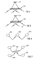
Figur 3 sind der Sender 16 und das diffraktive Element 22a ausFigur 2 detailliert dargestellt. Das diffraktive Element 22a ist als Hologrammfolie mit einem Liniengitter derart ausgebildet, das die vom Sender 16 senkrecht auf die Hologrammfolie einstrahlende Strahlung in die erste Ordnung 24 und die minus erste Ordnung 26 gebeugt wird. Dieser Effekt der Beugung am Gitter ist in der Physik allgemein bekannt und in zahlreichen Lehrbüchern beschrieben. Erste und minus erste Beugungsordnung haben dabei dieselbe Intensität. In Transmissionsrichtung, also in gerader Richtung vom Sender 16 aus gesehen, liegt die nullte Ordnung, in die gegebenenfalls auch keine Intensität fließen kann. - Empfängerseitig ist das diffraktive Element 22b so gestaltet, dass nur das Licht der ersten Ordnung zu den Empfängern 18 geleitet wird und die anderen Ordnungen, also die minus erste Ordnung oder höhere Ordnungen, ausgeblendet werden. Dies ist beispielsweise durch die Verwendung geblazter Gitter oder sogenannter holografischer Linsen möglich.
- Die diffraktiven Elemente 22a, 22b können darüber hinaus besondere fokussierende Eigenschaften besitzen, beispielsweise um das divergente, kegelförmige Strahlbündel des Senders 16 in ein solches mit zylindrischem Querschnitt zu verwandeln. Bei derartigen diffraktiven Elementen 22a ist die minus erste Ordnung 26 unter Umständen divergent und wird mittels geeigneter weiterer Maßnahmen ebenfalls als Nutzstrahlung verwendet .
- In den
Figuren 4 und 5 ist eine Variation ausFigur 3 dargestellt. Das diffraktive Element 22a besteht hier aus einer Überlagerung von zwei jeweils um 180 Grad gegeneinander verdrehten gebeugten Strukturen, von denen jede überwiegend in die erste Ordnung beugt. InFigur 4 sind beide Strukturen in einer Schicht überlagert. Dies kann beispielsweise durch Doppelbelichtung eines Hologramms erzielt werden. Wie inFigur 5 gezeigt, können diese beiden Strukturen jedoch auch in getrennten Schichten erzeugt werden und anschließend beispielsweise aufeinander laminiert werden. So entstehen zwei in entgegengesetzter Richtung gebeugte, in gewünschter Weise fokussierende Teilstrahlen der 1. Ordnung. Die ebenfalls vorhandenen Strahlen der minus ersten Ordnung werden hierbei nicht ausgenützt. InFigur 6 ist eine Anordnung von diffraktiven Elementen 22a, 22b gezeigt. Der Weg der Strahlung des Senders 16 ist durch die Pfeile schematisiert eingezeichnet. Das mittlere diffraktive Element 22a ist im Bereich des hier nicht gezeigten Senders 16 angeordnet und beugt die Strahlung in der ersten Ordnung über die nicht eingezeichnete totalreflektierende Glas-Luft-Grenzfläche zu den äußeren Empfängern 18. - In
Figur 7 ist eine Variation der inFigur 6 gezeigten Anordnung dargestellt. Hier sind fünf diffraktive Elemente 22 gezeigt. Vier dieser fünf diffraktiven Elemente 22a, 22b sind in Form eines Quadrates angeordnet, in dessen Zentrum das fünfte diffraktive Element 22a angeordnet ist. Im Bereich des fünften diffraktiven Elementes 22a ist der Sender (nicht eingezeichnet) angeordnet, welcher die Strahlung in die vier äußeren diffraktiven Elemente 22b leitet. Die äußeren, im Bereich der Empfänger 18 angeordneten diffraktiven Elemente 22b können natürlich auch in Form eines Rechtecks, in Form einer Raute, aber auch in Form eines Dreiecks oder einer anderen geometrischen Form angeordnet sein. Im zentralen diffraktiven Element 22a des Senders 16 sind jedoch so viele Linienstrukturen überlagert, wie Empfänger 18 vorhanden sind. - Prinzipiell können hier auch die Elemente 22b als Retroreflektor ausgebildet sein und die Strahlung in den Bereich des Senders zurückstrahlen, wo dann der Empfänger 18 angeordnet ist. Darüber hinaus können die Elemente 22b die Strahlung auch in Richtung eines gemeinsamen Empfängers 18 leiten, so daß beispielsweise zwei nebeneinander angeordnete Elemente 22b die Strahlung auf einen gemeinsamen Empfänger 18 lenken.
Claims (8)
- Regensensor, insbesondere für ein Kraftfahrzeug, mit mindestens einem Strahlung abgebenden Sender (16), mindestens einem, die Strahlung des Senders (16) empfangenden Empfänger (18) und mindestens einem, im Bereich des Senders angeordneten, holographisch ausgebildeten diffraktiven Element (22a, 22b), dadurch gekennzeichnet, daß das Element (22a, 22b) eine liniengitterartige Struktur aufweist und die Strahlung in eine erste und eine minus erste Ordnung beugt, und daß mehr Empfänger (18) als Sender (16) vorgesehen sind.
- Regensensor nach Ansprüch 1, dadurch gekennzeichnet, daß das Element (22a, 22b) fokussierende Eigenschaften aufweist.
- Regensensor nach einem der vorhergehenden Ansprüche, dadurch gekennzeichnet, daß mindestens ein weiteres Element (22a, 22b) vorgesehen ist, das zumindest teilweise als Retroreflektor ausgebildet ist.
- Regensensor nach einem der vorhergehenden Ansprüche, dadurch , gekennzeichnet, daß mindestens ein Element (22a, 22b) und/oder ein weiteres Element (22a, 22b) eine mehrschichtige Struktur aufweist.
- Regensensor nach einem der vorhergehenden Ansprüche, dadurch gekennzeichnet, daß mindestens ein Element (22a, 22b) und/oder ein weiteres Element (22a, 22b) mehrere Strukturen aufweist, die in einer Schicht überlagert sind.
- Regensensor nach einem der vorhergehenden Ansprüche, dadurch gekennzeichnet, daß mindestens ein Element (22a, 22b) und/oder mindestens ein weiteres Element (22a, 22b) in und/oder auf einer Scheibe eines Kraftfahrzeugs angeordnet sind.
- Regensensor nach einem der vorhergehenden Ansprüche, dadurch gekennzeichnet, daß ein Element (22a, 22b) und/oder ein weiteres Element (22a, 22b) eine Beugungseffizienz von 20 bis 80 Prozent, insbesondere von 40 bis 80 Prozent, vorzugsweise von 60 bis 80 Prozent aufweist.
- Regensensor nach Anspruch 7, dadurch gekennzeichnet, daß die Beugungseffizienz des Elements (22a, 22b) und/oder des weiteren Elements kleiner als 100 Prozent, insbesondere kleiner als 90 Prozent, vorzugsweise kleiner als 85 Prozent ist.
Applications Claiming Priority (5)
| Application Number | Priority Date | Filing Date | Title |
|---|---|---|---|
| DE10158097 | 2001-11-27 | ||
| DE10158097 | 2001-11-27 | ||
| DE10229200A DE10229200A1 (de) | 2001-11-27 | 2002-06-28 | Regensensor, insbesondere für ein Kraftfahrzeug |
| DE10229200 | 2002-06-28 | ||
| PCT/DE2002/003487 WO2003048748A1 (de) | 2001-11-27 | 2002-09-17 | Regensensor, insbesondere für ein kraftfahrzeug |
Publications (2)
| Publication Number | Publication Date |
|---|---|
| EP1451557A1 EP1451557A1 (de) | 2004-09-01 |
| EP1451557B1 true EP1451557B1 (de) | 2008-08-13 |
Family
ID=26010660
Family Applications (1)
| Application Number | Title | Priority Date | Filing Date |
|---|---|---|---|
| EP02774382A Expired - Lifetime EP1451557B1 (de) | 2001-11-27 | 2002-09-17 | Regensensor, insbesondere für ein kraftfahrzeug |
Country Status (4)
| Country | Link |
|---|---|
| US (1) | US6842271B2 (de) |
| EP (1) | EP1451557B1 (de) |
| JP (1) | JP2005512048A (de) |
| WO (1) | WO2003048748A1 (de) |
Families Citing this family (9)
| Publication number | Priority date | Publication date | Assignee | Title |
|---|---|---|---|---|
| DE10229239A1 (de) * | 2002-06-28 | 2004-01-15 | Robert Bosch Gmbh | Regensensor, insbesondere für ein Kraftfahrzeug |
| DE102004050765A1 (de) * | 2004-10-16 | 2006-04-27 | Robert Bosch Gmbh | Optischer Sensor zur Detektion von Feuchtigkeit auf einer Scheibe eines Kraftfahrzeugs |
| DE202006000742U1 (de) * | 2006-01-18 | 2007-05-24 | Trw Automotive Electronics & Components Gmbh & Co. Kg | Optische Sensorvorrichtung |
| US20070188122A1 (en) * | 2006-02-16 | 2007-08-16 | Denso International America, Inc. | Rain sensing automatic power windows |
| DE102007036492B4 (de) * | 2007-08-01 | 2009-07-30 | Trw Automotive Electronics & Components Gmbh & Co. Kg | Optische Sensorvorrichtung |
| KR101101538B1 (ko) | 2008-04-22 | 2012-01-02 | 테에르베 오토모티브 일렉트로닉스 운트 콤포넌츠 게엠베하 | 광 센서 장치 |
| DE102008061616B4 (de) * | 2008-12-11 | 2021-06-10 | Bcs Automotive Interface Solutions Gmbh | Optische Sensorvorrichtung |
| DE102018200626A1 (de) | 2018-01-16 | 2019-07-18 | Robert Bosch Gmbh | Detektionsvorrichtung zur Detektion von Verschmutzungen |
| DE102018117559A1 (de) | 2018-07-20 | 2020-01-23 | Valeo Schalter Und Sensoren Gmbh | Regensensor |
Family Cites Families (14)
| Publication number | Priority date | Publication date | Assignee | Title |
|---|---|---|---|---|
| IT212441Z2 (it) * | 1987-07-31 | 1989-07-04 | Veglia Borletti Srl | Dispositivo sensore della presenza di gocce di acqua su un cristallo di un veicolo e apparecchiatura dicomando di un tergicristallo provvista del detto dispositivo |
| CH693968A5 (de) * | 1993-04-21 | 2004-05-14 | Fraunhofer Ges Forschung | Verfahren und Vorrichtung fuer die Topographiepruefung von Oberflaechen. |
| DE4413758C2 (de) | 1993-04-21 | 1998-09-17 | Fraunhofer Ges Forschung | Vorrichtung und Verfahren zur Prüfung der Gestalt einer Oberfläche eines zu vermessenden Objektes |
| US5671050A (en) | 1994-11-07 | 1997-09-23 | Zygo Corporation | Method and apparatus for profiling surfaces using diffracative optics |
| DE19512864C1 (de) * | 1995-04-06 | 1996-08-22 | Sekurit Saint Gobain Deutsch | Autoglasscheibe für einen Regensensor |
| DE19701258A1 (de) * | 1996-01-18 | 1997-07-24 | Itt Mfg Enterprises Inc | Regensensor mit planarer Koppelfolie |
| JP3200391B2 (ja) * | 1997-03-21 | 2001-08-20 | 日本板硝子株式会社 | 自動車用ウインドシールドガラス |
| JPH1137927A (ja) | 1997-07-22 | 1999-02-12 | Nippon Sheet Glass Co Ltd | レインセンサを備えた透明基板 |
| JPH11148899A (ja) * | 1997-11-14 | 1999-06-02 | Nippon Sheet Glass Co Ltd | 透明基板の水滴検出装置 |
| JPH11183370A (ja) * | 1997-12-17 | 1999-07-09 | Nippon Sheet Glass Co Ltd | レインセンサの保護方法 |
| DE19943887A1 (de) * | 1998-09-15 | 2000-03-23 | Bosch Gmbh Robert | Optischer Sensor |
| JP2002524756A (ja) * | 1998-09-15 | 2002-08-06 | ローベルト ボツシユ ゲゼルシヤフト ミツト ベシユレンクテル ハフツング | 光学センサ |
| JP2000136998A (ja) * | 1998-11-02 | 2000-05-16 | Central Glass Co Ltd | 雨滴検出装置 |
| JP2000162123A (ja) * | 1998-11-30 | 2000-06-16 | Central Glass Co Ltd | 雨滴検出装置 |
-
2002
- 2002-09-17 US US10/470,452 patent/US6842271B2/en not_active Expired - Fee Related
- 2002-09-17 WO PCT/DE2002/003487 patent/WO2003048748A1/de not_active Ceased
- 2002-09-17 JP JP2003549894A patent/JP2005512048A/ja active Pending
- 2002-09-17 EP EP02774382A patent/EP1451557B1/de not_active Expired - Lifetime
Also Published As
| Publication number | Publication date |
|---|---|
| EP1451557A1 (de) | 2004-09-01 |
| US6842271B2 (en) | 2005-01-11 |
| WO2003048748A1 (de) | 2003-06-12 |
| JP2005512048A (ja) | 2005-04-28 |
| US20040113105A1 (en) | 2004-06-17 |
Similar Documents
| Publication | Publication Date | Title |
|---|---|---|
| DE68925502T2 (de) | Optische Kopfanordnung zum Lesen von in einem Aufzeichnungsmedium gespeicherten Informationen | |
| EP2112039A2 (de) | Optische Sensorvorrichtung | |
| EP2000373B1 (de) | Optische Sensorvorrichtung zur Erfassung einer Benetzung und Verfahren zur Herstellung dieser Sensorvorrichtung | |
| DE102008061616B4 (de) | Optische Sensorvorrichtung | |
| DE69321329T2 (de) | Vorrichtung zur Detektion einer Verschiebung | |
| EP2120025B1 (de) | Optische Sensorvorrichtung zur Detektion von Umgebungslicht | |
| DE19835972C1 (de) | Optoelektronische Positionserfassungseinrichtung zur absoluten Weg- oder Winkelbestimmung sowie Verwendung einer solchen Einrichtung | |
| DE102007036492A1 (de) | Optische Sensorvorrichtung | |
| DE102004019332A1 (de) | Optischer Drehgeber | |
| EP1396704A2 (de) | Interferenzielle Positionsmesseinrichtung | |
| EP0476361B1 (de) | Reflexionslichtschranke | |
| EP1451557A1 (de) | Regensensor, insbesondere für ein kraftfahrzeug | |
| DE68914804T2 (de) | Optische Abtastvorrichtung, geeignetes Spiegelobjektiv für diese Vorrichtung und optische Schreib- und/oder Leseanordnung mit der Abtastvorrichtung. | |
| EP0807842B1 (de) | Optische Anordnung mit diffraktivem optischen Element | |
| DE69605266T2 (de) | Plattenförmige Beleuchtungsvorrichtung | |
| DE19521295C2 (de) | Lichtelektrische Positionsmeßeinrichtung | |
| DE19938869A1 (de) | Optisches Verschiebungsmeßsystem | |
| DE10229200A1 (de) | Regensensor, insbesondere für ein Kraftfahrzeug | |
| EP2920603B1 (de) | Sensor zur erkennung und lokalisierung von laserstrahlungsquellen | |
| DE102016217846A1 (de) | Fabry-Pérot-Interferometer-Einheit, Verfahren zum Betreiben einer Fabry-Pérot-Interferometer-Einheit und Verfahren zum Herstellen einer Fabry-Pérot-Interferometer-Einheit | |
| WO2018228807A1 (de) | Filtereinrichtung für einen optischen sensor | |
| EP3963357B1 (de) | Abstandsmesssystem | |
| DE102011002299A1 (de) | Optikträger | |
| DE102007055497B4 (de) | Optischer Sensor für ein Kraftfahrzeug | |
| WO2011058190A1 (de) | Vorrichtung und verfahren zum lokalisieren von modulierten, optischen strahlungsquellen |
Legal Events
| Date | Code | Title | Description |
|---|---|---|---|
| PUAI | Public reference made under article 153(3) epc to a published international application that has entered the european phase |
Free format text: ORIGINAL CODE: 0009012 |
|
| 17P | Request for examination filed |
Effective date: 20040628 |
|
| AK | Designated contracting states |
Kind code of ref document: A1 Designated state(s): AT BE BG CH CY CZ DE DK EE ES FI FR GB GR IE IT LI LU MC NL PT SE TR |
|
| 17Q | First examination report despatched |
Effective date: 20070117 |
|
| GRAP | Despatch of communication of intention to grant a patent |
Free format text: ORIGINAL CODE: EPIDOSNIGR1 |
|
| GRAS | Grant fee paid |
Free format text: ORIGINAL CODE: EPIDOSNIGR3 |
|
| GRAA | (expected) grant |
Free format text: ORIGINAL CODE: 0009210 |
|
| AK | Designated contracting states |
Kind code of ref document: B1 Designated state(s): DE ES FR GB IT SE |
|
| REG | Reference to a national code |
Ref country code: GB Ref legal event code: FG4D Free format text: NOT ENGLISH |
|
| REF | Corresponds to: |
Ref document number: 50212647 Country of ref document: DE Date of ref document: 20080925 Kind code of ref document: P |
|
| PGFP | Annual fee paid to national office [announced via postgrant information from national office to epo] |
Ref country code: ES Payment date: 20080922 Year of fee payment: 7 |
|
| REG | Reference to a national code |
Ref country code: SE Ref legal event code: TRGR |
|
| REG | Reference to a national code |
Ref country code: ES Ref legal event code: FG2A Ref document number: 2307794 Country of ref document: ES Kind code of ref document: T3 |
|
| PGFP | Annual fee paid to national office [announced via postgrant information from national office to epo] |
Ref country code: GB Payment date: 20080922 Year of fee payment: 7 |
|
| PGFP | Annual fee paid to national office [announced via postgrant information from national office to epo] |
Ref country code: IT Payment date: 20080925 Year of fee payment: 7 |
|
| PLBE | No opposition filed within time limit |
Free format text: ORIGINAL CODE: 0009261 |
|
| STAA | Information on the status of an ep patent application or granted ep patent |
Free format text: STATUS: NO OPPOSITION FILED WITHIN TIME LIMIT |
|
| 26N | No opposition filed |
Effective date: 20090514 |
|
| EUG | Se: european patent has lapsed | ||
| GBPC | Gb: european patent ceased through non-payment of renewal fee |
Effective date: 20090917 |
|
| PG25 | Lapsed in a contracting state [announced via postgrant information from national office to epo] |
Ref country code: GB Free format text: LAPSE BECAUSE OF NON-PAYMENT OF DUE FEES Effective date: 20090917 |
|
| PGFP | Annual fee paid to national office [announced via postgrant information from national office to epo] |
Ref country code: DE Payment date: 20101126 Year of fee payment: 9 |
|
| PG25 | Lapsed in a contracting state [announced via postgrant information from national office to epo] |
Ref country code: IT Free format text: LAPSE BECAUSE OF NON-PAYMENT OF DUE FEES Effective date: 20090917 |
|
| PG25 | Lapsed in a contracting state [announced via postgrant information from national office to epo] |
Ref country code: SE Free format text: LAPSE BECAUSE OF NON-PAYMENT OF DUE FEES Effective date: 20090918 |
|
| REG | Reference to a national code |
Ref country code: ES Ref legal event code: FD2A Effective date: 20110711 |
|
| PG25 | Lapsed in a contracting state [announced via postgrant information from national office to epo] |
Ref country code: ES Free format text: LAPSE BECAUSE OF NON-PAYMENT OF DUE FEES Effective date: 20110629 |
|
| PG25 | Lapsed in a contracting state [announced via postgrant information from national office to epo] |
Ref country code: ES Free format text: LAPSE BECAUSE OF NON-PAYMENT OF DUE FEES Effective date: 20090918 |
|
| PGFP | Annual fee paid to national office [announced via postgrant information from national office to epo] |
Ref country code: SE Payment date: 20080930 Year of fee payment: 7 |
|
| PGFP | Annual fee paid to national office [announced via postgrant information from national office to epo] |
Ref country code: FR Payment date: 20111005 Year of fee payment: 10 |
|
| REG | Reference to a national code |
Ref country code: FR Ref legal event code: ST Effective date: 20130531 |
|
| PG25 | Lapsed in a contracting state [announced via postgrant information from national office to epo] |
Ref country code: DE Free format text: LAPSE BECAUSE OF NON-PAYMENT OF DUE FEES Effective date: 20130403 |
|
| REG | Reference to a national code |
Ref country code: DE Ref legal event code: R119 Ref document number: 50212647 Country of ref document: DE Effective date: 20130403 |
|
| PG25 | Lapsed in a contracting state [announced via postgrant information from national office to epo] |
Ref country code: FR Free format text: LAPSE BECAUSE OF NON-PAYMENT OF DUE FEES Effective date: 20121001 |