EP1451039B1 - Kupplungsvorrichtung für einen lastträger - Google Patents
Kupplungsvorrichtung für einen lastträger Download PDFInfo
- Publication number
- EP1451039B1 EP1451039B1 EP02778148A EP02778148A EP1451039B1 EP 1451039 B1 EP1451039 B1 EP 1451039B1 EP 02778148 A EP02778148 A EP 02778148A EP 02778148 A EP02778148 A EP 02778148A EP 1451039 B1 EP1451039 B1 EP 1451039B1
- Authority
- EP
- European Patent Office
- Prior art keywords
- shaft
- sleeve
- lever link
- coupling device
- pin
- Prior art date
- Legal status (The legal status is an assumption and is not a legal conclusion. Google has not performed a legal analysis and makes no representation as to the accuracy of the status listed.)
- Expired - Lifetime
Links
- 230000008878 coupling Effects 0.000 title claims description 36
- 238000010168 coupling process Methods 0.000 title claims description 36
- 238000005859 coupling reaction Methods 0.000 title claims description 36
- 230000000717 retained effect Effects 0.000 description 1
Images


Classifications
-
- B—PERFORMING OPERATIONS; TRANSPORTING
- B60—VEHICLES IN GENERAL
- B60R—VEHICLES, VEHICLE FITTINGS, OR VEHICLE PARTS, NOT OTHERWISE PROVIDED FOR
- B60R9/00—Supplementary fittings on vehicle exterior for carrying loads, e.g. luggage, sports gear or the like
- B60R9/06—Supplementary fittings on vehicle exterior for carrying loads, e.g. luggage, sports gear or the like at vehicle front or rear
Definitions
- the present invention relates to a coupling device, for coupling a load carrier to a vehicle, preferably to the rear section of the vehicle.
- the coupling device comprises a sleeve, which is mounted on the vehicle, and a shaft, which is mounted on the load carrier, and the coupling is realized in that the shaft is mounted into the sleeve, whereupon the shaft is secured in the sleeve by means of a securing device.
- Coupling devices of the described type are commonly seen. They generally appear as so-called “hitch mounts” or “hitch posts,” primarily on the American market, and there preferably on vehicles such as smaller platform-equipped vehicles, delivery vans and similar vehicles. These devices preferably comprise a sleeve of square material, which is secured to the vehicle, and a shaft consisting of square material, which is secured to the load carrier.
- the securing device usually consists of a pin that is introduced through holes in the sleeve and shaft, which holes line up with one another when the shaft is mounted in the sleeve.
- WO 94/055266 which discloses the features of the preamble of claims 1 and 6 a load carrying arrangement is disclosed in which a connecting shaft is inserted into a recess in a vehicle's coachwork and retained by clamping a hooked arm onto a pin protruding into the recess.
- the invention now proposed overcomes the aforementioned disadvantages by means of a coupling device of the type described above, characterized in that the securing device is arranged on the shaft.
- the securing device consists of a lever link which, at a first end, is pivotably arranged on the shaft at the end of the shaft that is mounted to the sleeve and, at a second end, in connection by means of a tension mechanism with the shaft, by means of which tension mechanism the lever link can be pivoted in a direction away from the shaft, whereupon the lever link and the shaft are brought into secure clamping engagement with the sleeve when the shaft is mounted to the sleeve.
- the sleeve has a pin that extends inside the sleeve between the inner walls of the sleeve and the lever link has a notch that engages with the pin in form-locking fashion, whereupon the secure clamping engagement occurs between the inner walls of the sleeve and the shaft respectively between said pin and notch.
- the lever link is acted upon by an elastic element in a direction away from the shaft, whereupon the lever link is pushed against the pin when the shaft is mounted to the sleeve, and whereupon the notch in the lever link snaps into contact with the pin when the shaft is introduced into the sleeve.
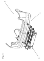
- Figure 1 is a schematic view of a rear section 1 of a vehicle.
- a load carrier 2 is coupled to the rear section by means of coupling devices 3.
- Figure 2 show that the coupling device 3 comprises a sleeve 4, a shaft 5 and a securing device 6.
- a mounting plate 7 is arranged on the sleeve 4 and the mounting plate joins the sleeve to the vehicle (not shown in the figure).
- Figure 3 shows that a first end 8 of the shaft 5 is mounted to the sleeve 4, the end 8 is inserted into the sleeve 4.
- a second end 9 of the shaft 5 is joined to the load carrier 2 (not shown in the figure).
- the securing device 6 is described in greater detail below with reference to figures 6 - 8.
- the securing device comprises a lever link 10 which, at a first end 11, is pivotably connected by means of a pivot axes 12 to the first end 8 of the shaft 5.
- the lever link 10 extends along the shaft 5 and has at its second end 13 a tension mechanism 14, by means of which the lever link can be pivoted around the pivot axes 12 away from the shaft 5 in the direction indicated by the arrow P.
- the tension mechanism comprises a nut 15 which is fixedly connected to the lever link in a known manner.
- a screw 16 cooperates with the nut 15, which screw 16 is equipped with a knob 17.
- the screw 16 is threaded into the nut 15, and the screw 16 is in abutment with the shaft 5 at the end 18 of the screw opposite to the knob.
- the elastic element 19 is connected in a known manner at a first end 20 to the lever link 10, and at a second end 21 in abutment with the shaft 5.
- the lever link is depicted with a U-shaped cross-section and, as shown, the lever link straddles the shaft.
- This shape is of value per se, in that the lever link is thereby given guidance in relation to the shaft, although this shape is of no importance to the function of the invention, and the lever link may exhibit any cross-section whatsoever that is sufficiently strong to be able to function satisfactorily.
- the sleeve 4 has a pin 22 that extends transversely in the sleeve, while the lever link 10 has a notch 23.
- the function of the pin and the notch will be described below.
- Figure 10 shows a coupling device according to the present invention that lacks the pin 22 and, in this arrangement, the connection is realized in that the lever link 10 and the shaft 5 are pushed against the inner walls 24 of the sleeve 4 to produce a fixed and secure connection.
- the sleeve part has been depicted in the description above as a square tube, and the shaft part as a round tube. It will be apparent to one skilled in the art that both the sleeve part and the shaft part can exhibit any cross-section whatsoever, assuming that the shaft part can be inserted into the sleeve part. It is also apparent to the one skilled in the art, with regards to the designs where the pin 22 engages with the notch 23, that the wall parts 26 and 27, fig.9, of the sleeve 4 can be omitted.
Landscapes
- Engineering & Computer Science (AREA)
- Mechanical Engineering (AREA)
- Fittings On The Vehicle Exterior For Carrying Loads, And Devices For Holding Or Mounting Articles (AREA)
- Pivots And Pivotal Connections (AREA)
- Mutual Connection Of Rods And Tubes (AREA)
Claims (10)
- Kopplungsvorrichtung (3) zur Koppelung eines Lastenträgers (2) mit einem Fahrzeug, vorzugsweise mit dem Heckabschnitt (1) des Fahrzeugs, wobei die Kopplungsvorrichtung eine Buchse (4) aufweist, die an den Heckabschnitt des Fahrzeugs montiert ist, und eine Stange (5), die an den Lastenträger (2) montiert ist, wobei die Kopplung so verwirklicht ist, dass die Stange (5) in die Buchse (4) montiert ist, woraufhin die Stange (5) mittels einer auf der Stange (5) angeordneten Feststellvorrichtung (6) mit der Buchse fest verbunden wird, die Feststellvorrichtung (6) umfasst einen Hebelverbinder (10), der an einem ersten Ende (11) mittels einer Schwenkachse (12) schwenkbar auf der Stange (5) an deren ersten Ende (8) angeordnet ist, wobei das erste Ende (8) an die Buchse (4) montiert ist, dadurch gekennzeichnet, dass die Feststellvorrichtung an einem zweiten Ende (13) mittels eines Spannmechanismusses (14) mit der Stange (5) in Verbindung ist, wobei der Hebelverbinder (10) durch den Spannmechanismus in eine Richtung (P) weg von der Stange (5) schwenkbar ist, woraufhin der Hebelverbinder (10) und die Stange (5) mit den Innenwänden (25) der Buchse (4) in einen festklemmenden Eingriff gebracht werden, wenn die Stange (5) an die Buchse (4) montiert wird.
- Kopplungsvorrichtung nach Anspruch 1, dadurch gekennzeichnet, dass die Buchse (4) einen Stift (22) umfasst, der sich quer innerhalb der Buchse (4) erstreckt, und dass der Hebelverbinder (10) eine Nut (23) aufweist, wobei der Hebelverbinder (10) durch den Spannmechanismus (14) in eine Richtung (P) weg von der Stange schwenkbar ist, so dass die Nut (23) mit dem Stift (22) in Eingriff gebracht wird, wodurch die Stange über den Eingriff zwischen der Stange (5) und den Innenwänden (25) der Buchse und jeweils zwischen dem Stift (22) und der Nut (23) in eine festklemmende Verbindung mit der Buchse (4) gebracht wird.
- Kopplungsvorrichtung nach Anspruch 2, dadurch gekennzeichnet, dass auf den Hebelverbinder (10) durch ein elastisches Element (19) eingewirkt wird, das den Hebelverbinder (10) in eine Richtung (P) weg von der Stange drückt, woraufhin der Hebelverbinder gegen den Stift (22) gedrückt wird, wenn die Stange (5) in eine Richtung (F) in die Buchse (4) montiert wird, woraufhin die Nut (23) um den Stift (22) herum einschnappt, wenn die Stange (5) in eine Stellung bewegt wird, in welcher die Nut auf den Stift trifft.
- Kopplungsvorrichtung nach Anspruch 2 oder 3, dadurch gekennzeichnet, dass der Umfang der Buchse (4) durch die Buchsenwände (24) und den Stift (22) begrenzt wird.
- Kopplungsvorrichtung nach einem der vorherigen Ansprüche, dadurch gekennzeichnet, dass die Buchse ein quadratische Rohr ist und die Stange ein rundes Rohr ist.
- Kopplungsvorrichtung zur Koppelung eines Lastenträgers (2) mit dem Heckabschnitt eines Fahrzeugs, wobei die Kopplungsvorrichtung eine Stange (5) aufweist, die an den Lastenträger (2) montiert ist, und die Kopplung mit dem Fahrzeug so verwirklicht ist, dass bei Benutzung die Stange (5) in eine Buchse (4) am Fahrzeug montiert ist, woraufhin die Stange (5) mittels einer auf der Stange (5) angeordneten Feststellvorrichtung (6) mit der Buchse fest verbunden wird, die Feststellvorrichtung (6) umfasst einen Hebelverbinder (10), der an einem ersten Ende (11) mittels einer Schwenkachse (12) schwenkbar auf der Stange (5) an deren ersten Ende (8) angeordnet ist, wobei das erste Ende (8) an die Buchse (4) montiert ist, dadurch gekennzeichnet, dass die Feststellvorrichtung an einem zweiten Ende (13) mittels eines Spannmechanismusses (14) mit der Stange (5) in Verbindung ist, wobei der Hebelverbinder (10) durch den Spannmechanismus in eine Richtung (P) weg von der Stange (5) schwenkbar ist, woraufhin der Hebelverbinder (10) und die Stange (5) mit den Innenwänden (25) der Buchse (4) in einen festklemmenden Eingriff gebracht werden, wenn die Stange (5) an die Buchse (4) montiert wird.
- Kopplungsvorrichtung nach einem der vorherigen Ansprüche, dadurch gekennzeichnet, dass der Spannmechanismus (14) eine mit dem Hebelverbinder (10) fest verbundene Mutter (15), eine mit der Mutter (15) zusammenwirkende Schraube (16) umfasst, wobei die Schraube (16) mit einem Knauf (17) ausgestattet ist, wobei die Schraube in die Mutter eingeschraubt ist und mit dem Schraubenende (18) entgegengesetzt dem Knauf auf der Stange (5) aufsitzt.
- Kopplungsvorrichtung nach Anspruch 7, dadurch gekennzeichnet, dass die Kopplungsvorrichtung weiterhin ein elastisches Element (19) umfasst, das um die Schraube (16) herum angeordnet ist und an einem ersten Ende (20) mit dem Hebelverbinder (10) verbunden ist und an einem zweiten Ende auf der Stange (5) aufsitzt.
- Kopplungsvorrichtung nach Anspruch 8, dadurch gekennzeichnet, dass, wenn die Schraube (16) hochgeschraubt wird, der Hebelverbinder (10) zur Stange (5) hin entgegen die durch das elastische Element (19) ausgeübte Kraft heruntergedrückt werden kann.
- Kopplungsvorrichtung nach einem der vorhergehenden Ansprüche, dadurch gekennzeichnet, dass der Hebelverbinder (10) einen U-förmigen Querschnitt hat.
Applications Claiming Priority (3)
| Application Number | Priority Date | Filing Date | Title |
|---|---|---|---|
| SE0103674 | 2001-11-06 | ||
| SE0103674A SE520614C2 (sv) | 2001-11-06 | 2001-11-06 | Kopplingsanordning för en lastbärare |
| PCT/SE2002/001867 WO2003039912A1 (en) | 2001-11-06 | 2002-10-15 | Coupling device for a load carrier |
Publications (2)
| Publication Number | Publication Date |
|---|---|
| EP1451039A1 EP1451039A1 (de) | 2004-09-01 |
| EP1451039B1 true EP1451039B1 (de) | 2006-07-26 |
Family
ID=20285875
Family Applications (1)
| Application Number | Title | Priority Date | Filing Date |
|---|---|---|---|
| EP02778148A Expired - Lifetime EP1451039B1 (de) | 2001-11-06 | 2002-10-15 | Kupplungsvorrichtung für einen lastträger |
Country Status (4)
| Country | Link |
|---|---|
| EP (1) | EP1451039B1 (de) |
| DE (1) | DE60213458T2 (de) |
| SE (1) | SE520614C2 (de) |
| WO (1) | WO2003039912A1 (de) |
Families Citing this family (5)
| Publication number | Priority date | Publication date | Assignee | Title |
|---|---|---|---|---|
| FR2867120B1 (fr) | 2004-03-02 | 2006-04-28 | Renault Sas | Porte-charge destine a equiper l'arriere d'un vehicule automobile |
| DE102004033809B4 (de) * | 2004-07-12 | 2016-05-12 | Volkswagen Ag | Aufnahmevorrichtung für ein Fahrzeug |
| EP2428405B1 (de) * | 2010-09-13 | 2015-10-07 | WESTFALIA - Automotive GmbH | Kupplung für ein Lastenträger-System mit einem Spannteil |
| DE102014017019A1 (de) * | 2014-11-19 | 2016-05-19 | Westfalia-Automotive Gmbh | Lastenträgerkupplung |
| FR3138796B1 (fr) * | 2022-08-10 | 2024-06-28 | Renault Sas | Porte-charge d’un véhicule automobile |
Family Cites Families (2)
| Publication number | Priority date | Publication date | Assignee | Title |
|---|---|---|---|---|
| CA2143282A1 (en) * | 1992-09-08 | 1994-03-17 | Eberhard Tittel | Load carrying arrangement for attachment of a load carrier to the rear of a motor vehicle |
| SE9904409L (sv) * | 1999-12-03 | 2001-06-04 | Saab Automobile | Motorfordon med fästanordning för lasthållare, samt en lasthållare |
-
2001
- 2001-11-06 SE SE0103674A patent/SE520614C2/sv not_active IP Right Cessation
-
2002
- 2002-10-15 WO PCT/SE2002/001867 patent/WO2003039912A1/en not_active Ceased
- 2002-10-15 EP EP02778148A patent/EP1451039B1/de not_active Expired - Lifetime
- 2002-10-15 DE DE60213458T patent/DE60213458T2/de not_active Expired - Lifetime
Also Published As
| Publication number | Publication date |
|---|---|
| DE60213458T2 (de) | 2007-03-15 |
| SE0103674L (sv) | 2003-05-07 |
| EP1451039A1 (de) | 2004-09-01 |
| SE520614C2 (sv) | 2003-07-29 |
| SE0103674D0 (sv) | 2001-11-06 |
| DE60213458D1 (de) | 2006-09-07 |
| WO2003039912A1 (en) | 2003-05-15 |
Similar Documents
| Publication | Publication Date | Title |
|---|---|---|
| US5615904A (en) | Drawbar coupler for an automotive vehicle hitch rack | |
| EP2233360B2 (de) | Schnappverschluss in einem Rückspiegel | |
| CA2131472C (en) | Receiver hitch anti-rattle device | |
| US7862066B2 (en) | 3 way ATV/UTV tractor receiver hitch | |
| US5832572A (en) | Safety hook and latch plate therefor | |
| CA2728971C (en) | Safety brake system for trailers | |
| US7044493B1 (en) | Trailer hitch tow bar assembly | |
| CA2191150A1 (en) | Trailer hitch | |
| EP1451039A1 (de) | Kupplungsvorrichtung für einen lastträger | |
| JP2004338666A (ja) | 車両用牽引装置 | |
| US20020113408A1 (en) | Bumper unit having a hitching towing arrangement and a method of making same | |
| US20030090085A1 (en) | Trailer hitch with electrical connector | |
| US6979015B1 (en) | Trailer hitch assembly and method | |
| EP1008468A3 (de) | Kupplungsträger | |
| US6290247B1 (en) | Bicycle trailer hitch | |
| US8052172B1 (en) | Glad hand locking device | |
| US6360859B1 (en) | Device and method in braking systems for motor vehicles | |
| CN110294045A (zh) | 附接装置及其用途、具有这种附接装置的系统和车辆 | |
| ATE196099T1 (de) | Anhänger-kupplung für spiel-fahrzeuge, insbesondere traktorkupplung | |
| CA2287539A1 (en) | Lower steering arm assembly for an attaching device of a tractor | |
| KR100835599B1 (ko) | 분리가능한 트레일러 견인장치 | |
| WO2006126818A1 (en) | Fixed cellular phone for vehicle | |
| US20080008571A1 (en) | Wheel lift lock | |
| US20120050900A1 (en) | Trailer hitch mirror | |
| CA2287516A1 (en) | Lower steering arm assembly for an attaching device of a tractor |
Legal Events
| Date | Code | Title | Description |
|---|---|---|---|
| PUAI | Public reference made under article 153(3) epc to a published international application that has entered the european phase |
Free format text: ORIGINAL CODE: 0009012 |
|
| 17P | Request for examination filed |
Effective date: 20040518 |
|
| AK | Designated contracting states |
Kind code of ref document: A1 Designated state(s): AT BE BG CH CY CZ DE DK EE ES FI FR GB GR IE IT LI LU MC NL PT SE SK TR |
|
| AX | Request for extension of the european patent |
Extension state: AL LT LV MK RO SI |
|
| 17Q | First examination report despatched |
Effective date: 20050217 |
|
| RAP1 | Party data changed (applicant data changed or rights of an application transferred) |
Owner name: THULE SWEDEN AB Owner name: RENAULT SAS |
|
| GRAP | Despatch of communication of intention to grant a patent |
Free format text: ORIGINAL CODE: EPIDOSNIGR1 |
|
| GRAS | Grant fee paid |
Free format text: ORIGINAL CODE: EPIDOSNIGR3 |
|
| RIN1 | Information on inventor provided before grant (corrected) |
Inventor name: PERSON, JOAKIM Inventor name: VEUILLOT, OLIVIER Inventor name: ODIN, HANS Inventor name: PREMARTIN, ARNAUD |
|
| GRAA | (expected) grant |
Free format text: ORIGINAL CODE: 0009210 |
|
| AK | Designated contracting states |
Kind code of ref document: B1 Designated state(s): BE DE FR GB |
|
| REG | Reference to a national code |
Ref country code: GB Ref legal event code: FG4D |
|
| REF | Corresponds to: |
Ref document number: 60213458 Country of ref document: DE Date of ref document: 20060907 Kind code of ref document: P |
|
| REG | Reference to a national code |
Ref country code: FR Ref legal event code: RN |
|
| REG | Reference to a national code |
Ref country code: FR Ref legal event code: FC |
|
| EN | Fr: translation not filed | ||
| PLBE | No opposition filed within time limit |
Free format text: ORIGINAL CODE: 0009261 |
|
| STAA | Information on the status of an ep patent application or granted ep patent |
Free format text: STATUS: NO OPPOSITION FILED WITHIN TIME LIMIT |
|
| ET | Fr: translation filed | ||
| 26N | No opposition filed |
Effective date: 20070427 |
|
| PGFP | Annual fee paid to national office [announced via postgrant information from national office to epo] |
Ref country code: BE Payment date: 20121022 Year of fee payment: 11 |
|
| PGFP | Annual fee paid to national office [announced via postgrant information from national office to epo] |
Ref country code: GB Payment date: 20121019 Year of fee payment: 11 |
|
| BERE | Be: lapsed |
Owner name: *THULE SWEDEN A.B. Effective date: 20131031 Owner name: *RENAULT S.A.S. Effective date: 20131031 |
|
| GBPC | Gb: european patent ceased through non-payment of renewal fee |
Effective date: 20131015 |
|
| PG25 | Lapsed in a contracting state [announced via postgrant information from national office to epo] |
Ref country code: GB Free format text: LAPSE BECAUSE OF NON-PAYMENT OF DUE FEES Effective date: 20131015 |
|
| PG25 | Lapsed in a contracting state [announced via postgrant information from national office to epo] |
Ref country code: BE Free format text: LAPSE BECAUSE OF NON-PAYMENT OF DUE FEES Effective date: 20131031 |
|
| REG | Reference to a national code |
Ref country code: FR Ref legal event code: PLFP Year of fee payment: 14 |
|
| REG | Reference to a national code |
Ref country code: FR Ref legal event code: PLFP Year of fee payment: 15 |
|
| REG | Reference to a national code |
Ref country code: FR Ref legal event code: PLFP Year of fee payment: 16 |
|
| REG | Reference to a national code |
Ref country code: FR Ref legal event code: PLFP Year of fee payment: 17 |
|
| PGFP | Annual fee paid to national office [announced via postgrant information from national office to epo] |
Ref country code: DE Payment date: 20191021 Year of fee payment: 18 |
|
| PGFP | Annual fee paid to national office [announced via postgrant information from national office to epo] |
Ref country code: FR Payment date: 20191028 Year of fee payment: 18 |
|
| REG | Reference to a national code |
Ref country code: DE Ref legal event code: R119 Ref document number: 60213458 Country of ref document: DE |
|
| PG25 | Lapsed in a contracting state [announced via postgrant information from national office to epo] |
Ref country code: DE Free format text: LAPSE BECAUSE OF NON-PAYMENT OF DUE FEES Effective date: 20210501 Ref country code: FR Free format text: LAPSE BECAUSE OF NON-PAYMENT OF DUE FEES Effective date: 20201031 |
|
| P01 | Opt-out of the competence of the unified patent court (upc) registered |
Effective date: 20230528 |