EP1450497A2 - Communications device with Doppler frequency estimation functions - Google Patents
Communications device with Doppler frequency estimation functions Download PDFInfo
- Publication number
- EP1450497A2 EP1450497A2 EP04003841A EP04003841A EP1450497A2 EP 1450497 A2 EP1450497 A2 EP 1450497A2 EP 04003841 A EP04003841 A EP 04003841A EP 04003841 A EP04003841 A EP 04003841A EP 1450497 A2 EP1450497 A2 EP 1450497A2
- Authority
- EP
- European Patent Office
- Prior art keywords
- domain response
- time
- complex time
- response signals
- complex
- Prior art date
- Legal status (The legal status is an assumption and is not a legal conclusion. Google has not performed a legal analysis and makes no representation as to the accuracy of the status listed.)
- Granted
Links
Images








Classifications
-
- H—ELECTRICITY
- H04—ELECTRIC COMMUNICATION TECHNIQUE
- H04B—TRANSMISSION
- H04B7/00—Radio transmission systems, i.e. using radiation field
- H04B7/01—Reducing phase shift
Definitions
- the present invention relates to a communications device, and more particularly to a communications device for communication over wireless channels.
- FIG. 20 shows a simplified model of propagation between a base station and a mobile station.
- Carrier waves transmitted from an antenna of the base station BS travel over two or more different routes before arriving at a mobile station MS. This is known as "multipath," the phenomenon that results in radio signals' reaching the receiving end via a plurality of paths because of the reflection from objects such as mountains and buildings.
- multipath the phenomenon that results in radio signals' reaching the receiving end via a plurality of paths because of the reflection from objects such as mountains and buildings.
- the signal frequency observed at the moving mobile station MS is not constant, but varies since it is a sum of carrier frequency and Doppler frequency.
- the mobile station MS receives a plurality of such incoming radio wave signals with a broadened spectrum, experiencing significant fluctuations of received signal level, the phenomenon called "multipath fading.”
- one method measures the interval of Doppler fluctuations. Another method repeats channel estimation at constant intervals and uses the phase differences between the obtained channel estimates for estimation. With those generally known methods, however, it is difficult to estimate Doppler frequency in a stable and accurate way when the receiver is in such conditions where the signal-to-noise (S/N) ratio is low.
- S/N signal-to-noise
- a communications device for communication over wireless channels.
- This communications device comprises the following elements: a complex impulse response measurement unit, a phase difference calculator, an average operator, and a Doppler frequency estimator.
- the complex time-domain response measurement unit obtains complex time-domain response signals representing the characteristics of propagation paths.
- the phase difference calculator then calculates absolute phase differences between the complex time-domain response signals that are selected according to a predetermined algorithm.
- the average operator calculates a mean value of the absolute phase differences over a plurality of radio frames, and the Doppler frequency estimator estimates Doppler frequency by dividing the mean value by the time length of the radio frame.
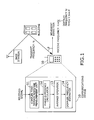
- FIG. 1 is a conceptual view of a communications device according to the present invention.
- This communications device 10 is implemented in, for example, a cellular handset or similar mobile communications equipment.
- the communications device 10 provides the capability of receiving radio waves in a multipath environment, and to this end, it comprises the following functional elements: a complex time-domain response measurement unit 11, a phase difference calculator 12, an average operator 13, and a Doppler frequency estimator 14.
- the complex time-domain response measurement unit 11 obtains "complex time-domain response signals" (or “complex impulse responses”), i.e., a set of measurements representing characteristics of the actual propagation paths. More specifically, the delay profile of a multipath channel can be obtained by calculating the power of a received signal in each short time interval. Because of multipath reflections, the delay profile is a series of impulses with different arrival times, each corresponding to a different propagation path. In the present invention, we call those individual impulses “impulse responses” or “complex impulse responses.” Detailed definition of complex impulse response will be discussed later.
- the phase difference calculator 12 calculates absolute phase differences between complex impulse responses that are selected with a predetermined algorithm. Those selected complex impulse responses are, for example, maximum complex impulse responses. We will use the term "maximum complex impulse responses" to refer to a set of complex impulse responses to be subjected to the phase difference calculator 12.
- the average operator 13 calculates a mean value of the absolute phase differences over a plurality of radio frames.
- the Doppler frequency estimator 14 divides the mean value by the length of the radio frame, thereby estimating the Doppler frequency.
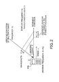
- FIG. 3A shows Doppler frequency in the case where a radio wave comes from the same direction as (or opposite direction to) the mobile station's velocity.
- f d,max v ⁇
- FIGS. 4A and 4B schematically show fading fluctuations due to Doppler effect. More specifically, FIG. 4A shows a situation where the mobile station MS receives multipath wave components coming from different directions, and FIG. 4B illustrates how the level of received radio wave signals varies with time, where the horizontal axis represents time and the vertical axis represents the received signal level.
- This model gives a simplified representation of fading-impaired radio waves, the level of which fluctuates as the mobile station MS moves.
- the received signal level drops at time point t1 and exhibits a peak at time point t2.
- the time point t1 is when the two multipath components A and B are 180-degree out of phase, whereas the time point t2 is when they are in phase.
- the time interval between 0 to t2 equals Doppler period, i.e., the reciprocal of Doppler frequency. In this sense, Doppler frequency is also called “fading frequency,” and Doppler period "fading period.”
- Doppler shift causes a variation of fading levels in the way described above, not only with downstream links (i.e., at mobile station receivers) but also with upstream links (i.e., at base station receivers).
- the drop of electric field intensity, as in the maximum fading effect at time point t1 in FIG. 4B, is particularly problematic because it increases data transmission errors in wireless communications. If the Doppler frequency can be estimated accurately, it will bring a substantial performance improvement to a radio communications system, because the system will be able to use a different communication technique or optimize the signal reception algorithm, depending on the Doppler period that is estimated.
- the adaptive system may increase the transmission rate by using, for example, a multilevel modulation technique such as 16-quadrature amplitude modulation (QAM) or 64QAM in the case of a low Doppler frequency.
- QAM 16-quadrature amplitude modulation
- the system may choose a binary phase shift keying (BPSK) technique or quadrature phase shift keying (QPSK) technique when the Doppler frequency is high.
- BPSK binary phase shift keying
- QPSK quadrature phase shift keying
- FIG. 5 provides an overview of channel estimation.
- the received signal fluctuates not only in the amplitude but also in the phase.
- a QPSK symbol is transmitted over a fading channel. While the transmitted symbol is at a signal point S1 in the I-Q plane, the fading channel causes a phase rotation of ⁇ degrees before the signal arrives at the receiving end. As result, the received symbol is observed at a different signal point S2, and without correction, it would be demodulated mistakenly as a different symbol.
- the receiving end has therefore to identify the channel variation, i.e., how much phase rotation the incoming signal is currently suffering due to the fading effect on the radio channel, and then to make an appropriate compensation for that phase rotation.
- the receiving end corrects the phase by - ⁇ degrees to reproduce the original symbol.
- pilot symbols are multiplexed in the transmission signal stream.
- the receiver extracts them from a received signal and estimates the amount of fading-induced phase rotation at the moment.
- the estimated channel parameters are used in synchronous detection of other received symbols, which enables the receiver to reproduce the original signals correctly.
- the channel estimator looks into the average behavior of many instances of pilot symbols, as opposed to relying on a single pilot symbol, because it is necessary to consider the presence of noises on the channel being observed. While a longer averaging interval may be desirable in terms of minimizing the effect of noises, it would not work well in an environment with a fast and large fading fluctuation. This is because a long averaging interval tends to involve dissimilar symbols with larger fluctuations, which leads to a greater estimation error.
- the channel estimator has to employ an adaptive method in determining the averaging interval. Specifically, the averaging interval is extended when a lower Doppler frequency is observed, so that the channel estimator can work more accurately. When a higher Doppler frequency is observed, the channel estimator shortens the averaging interval to prevent the estimation accuracy from being degraded by the fast fluctuations of fading characteristics.
- FIG. 6 illustrates the measurement of intervals of signal level variation that is caused by Doppler effects.
- the amplitude of a received signal is compared with a predetermined reference level to count the number of points at which the amplitude curve crosses that reference line.
- the resulting count value called "level crossing rate” (LCR)
- LCR level crossing rate
- the first existing algorithm requires the receiver to measure the variation of electrical field intensity continuously. To this end, the averaging of received signal levels should be repeated at short intervals, which, on the other hand, makes it difficult to accurately estimate a high fading frequency. Also, it is not easy to translate a given level crossing rate to an actual fading rate, since the behavior of multipath fading becomes more and more complicated as the number of propagation paths increases. In addition to the above, the LCR-based estimation is quite sensitive to the selection of its reference level. This could be a negative factor to accuracy and stability of estimates in such a system environment where the receiver experiences a large-scale fluctuation of average signal levels due to shadowing effects (described below).
- FIG. 7A illustrates a situation where shadowing occurs
- FIG. 7B shows variations of the signal reception level due to shadowing effects.
- shadowing refers to a long-term fluctuation of signals (as opposed to multipath fading, which is short-term fluctuations) which occurs when a line-of-sight propagation path is impaired by an obstacle for the duration of, for example, a few seconds to several tens of seconds.
- the mobile station MS can initially receive a radio wave from the sending base station BS through a direct line-of-sight path.
- the line-of-sight propagation path is lost and only reflected waves can reach there.
- the mobile station MS experiences a significant drop of received signal level as a result of the shadowing effect as illustrated in FIG. 7B.
- the shadowing degrades the accuracy of the first existing algorithm, which measures the level crossing rate with respect to a fixed reference level. That is, the Doppler frequency estimated with this technique fluctuates significantly when the mobile station MS encounters shadowing.
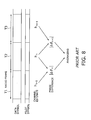
- FIG. 8 shows the concept of measurement of phase differences between channel estimates.
- the second existing algorithm estimates Doppler frequency by calculating a channel estimate frame by frame and then averaging the phase differences between the resultant channel estimates in absolute terms over a plurality of frames.
- the algorithm calculates a channel estimate h n-1 for the (n-1)th frame by averaging a plurality of pilot symbols contained in frame T1.
- it calculates a channel estimate h n for the nth frame by averaging pilot symbols in frame T2
- the algorithm calculates the phase difference ⁇ n between channel estimates as follows:
- the phase difference ⁇ n calculated in this way contains two kinds of components: a phase variation due to fading and a phase change due to frequency offset (carrier offset).
- frequency offset refers to the difference between transmitter frequency and receiver frequency.
- the base station In a 2-GHz band W-CDMA system, for example, the base station generates a carrier frequency of 2 GHz, as do the mobile stations. Those locally produced 2-GHz clock signals are, however, not identical in the strict sense. For example, the base station may generate 2.00001 GHz whereas a mobile station generates 1.9999 GHz.
- frequency offset There is always a difference in the frequency (i.e., frequency offset) between the sending end and receiving end, which could cause a phase rotation of transmitted signals, as the multipath fading does. Because of this frequency offset, mobile stations may experience a frequency offset-induced phase variation even in a fading-free environment.
- fading-induced phase variations tend to change their directions.
- the phase could rotate as follows: +10°, +10°, -10°, -10°, -10°, and so on.
- frequency offset-induced phase variations are unidirectional. With a frequency offset of, for example, 80 Hz, the phase rotates at the constant rate corresponding to that frequency.
- To average the phase differences ⁇ n as vector components is to average their frequency offset-induced components only, and the averaged result does not reflect their fading-induced components. This is because, as mentioned above, fading-induced components tend to change signs (e.g., +10°, +10°, -10°, -10°, -10°, etc, and their average is supposed to converge to zero over time.
- phase differences ⁇ n tend to repeat the same pattern at unit time intervals (e.g., +10°, +10°,...), and thus their mean value is not zero.
- scalar averaging should be implemented; in this case, the process has to average the absolute values of phase differences ⁇ n given by equation (3).
- the following equation (4) can replace the preceding equation (3).
- cos -1 ( h n ⁇ h n-1
- This equation (4) directly yields an absolute phase difference from the inner product of two consecutive channel estimates. By averaging these
- the second existing algorithm described above is, however, unable to cancel noise components, but allows such components to exert an influence on the result, because the algorithm averages phase differences in absolute terms.
- noise components tend to show random phase rotations over time, and the scalar averaging cannot eliminate such components, unlike vector averaging.
- the calculated Doppler frequency estimate is significantly affected by the noise components. With signals received in a noisy radio channel environment, the estimation often yields an inaccurate Doppler frequency that is greater than the actual value.
- Today's radio communications systems take advantage of diversity reception and error correction techniques to provide better performance even in low S/N conditions. They also have transmission power control functions to guarantee the required quality level of communications with minimum energy consumption and thus to provide longer talk time. For those reasons, the S/N ratio of received radio signals is not high in general, and it is hard to estimate Doppler frequency at high accuracy in such radio environments.
- the present invention is intended to address the shortcomings of the above-described conventional techniques, and to provide a communications device with an enhanced performance of Doppler frequency estimation that can work accurately even in low S/N conditions.
- the communications device 10 first calculates a series of complex impulse responses from a signal received in each radio frame interval T. Of all responses within a frame T, it finds a maximum complex impulse response, i.e., the complex impulse response with a maximum magnitude. In this way, the communications device 10 obtains a maximum complex impulse response for each radio frame T, as well as identifies the phase of that response. It subsequently calculates absolute phase differences between adjacent frames and then averages them over a plurality of radio frames, thus obtaining an estimate of Doppler frequency.
- Complex impulse responses are calculated from some signals with known properties, such as pilot symbols (synchronous channel signals, which the base station transmits continuously, can also serve the purpose). More specifically, the communications device 10 produces a local replica of such a known signal for use in calculating the correlation between a received signal and the replica. The resulting cross-correlation represents complex impulse responses.
- FIGS. 10A and 10B provide an overview of how the complex impulse response measurement unit 11 works (note that the complex time-domain response measurement unit 11 in FIG. 1 is renamed as such).
- the complex impulse response measurement unit 11 has a plurality of multipliers 11-1 to 11-8 and an adder 11-9 to calculate the cross-correlation between a received signal sequence and a pilot symbol sequence (which is a replica of pilot symbols).
- the received signal sequence contains pilot symbols, and thus the calculated cross-correlation exhibits a peak, or an impulse, at the time point where the received signal matches with the replica.
- the received signal consists of a plurality of multipath components
- the earliest wave produces a first impulse in the cross-correlation
- the next coming wave produces a second impulse, and this continues until all multipath waves appear.
- the process brings both a delay profile (see FIG. 10B) and complex impulse responses.
- the complex impulse response measurement unit 11 passes ⁇ n (i) to the phase difference calculator 12, which finds a maximum complex impulse response ⁇ n in each individual frame n and then calculates absolute phase differences as follows:
- cos -1 ( ⁇ n ⁇ n-1
- is averaged over N frames, and an estimate of Doppler frequency is obtained from the resultant mean value in the way described earlier in equation (5).
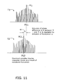
- FIG. 11 illustrates a variation of maximum complex impulse responses.
- the upper half of FIG. 11 shows a radio frame T1 with a maximum complex impulse response ⁇ 1 at point Pa1, while the lower half shows the subsequent radio frame T2 with a maximum complex impulse response ⁇ 2 at point Pa2.
- the peak time position has moved from Pa1 to Pa2 in a single frame period. This displacement is so quick and large that it introduces extraneous variations into the calculated phase difference ⁇ between ⁇ 1 and ⁇ 2, which results in an increased estimation error.
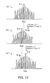
- FIG. 12 shows an alternative way to calculate the phase difference between complex impulse responses in two consecutive frames.
- the topmost part of FIG. 12 shows a radio frame T1 with a maximum complex impulse response ⁇ 1 observed at point Pa1.
- the middle part shows the next radio frame T2 with a maximum complex impulse response ⁇ 2 at point Pa2.
- the bottommost part shows the subsequent radio frame T3 with a maximum complex impulse response ⁇ 3 at point Pa3.
- the alternative method first calculates the phase difference between the maximum complex impulse response ⁇ 1 in the first radio frame T1 and a complex impulse response ⁇ 2a located at the corresponding position Pa1 (i.e., at the same position as the maximum complex impulse response ⁇ 1) in the second radio frame T2.
- the alternative method finds a maximum complex impulse response of the (n-1) th frame and uses that time position t1 to extract a complex impulse response in the nth frame. Then it calculates the absolute phase difference between the (n-1)th frame's maximum complex impulse response and the nth frame's complex impulse response, both of which are located at the fixed time position t1.
- the alternative method finds a maximum complex impulse response of the nth frame and uses that time position t2 to extract a complex impulse response in the (n+1)th frame.
- the calculation of an absolute phase difference then takes place between the nth frame's maximum complex impulse response and the (n+1)th frame's complex impulse response, both residing at the fixed time position t2.
- the present invention estimates the Doppler frequency based on maximum complex impulse responses found in a given series of frames. It should be noted that maximum complex impulse responses represent multipath components with the highest S/N ratios among others. This means that the proposed method selectively uses signal components with maximum S/N ratios in estimating Doppler frequency, thus preventing the estimation process from being influenced by noise components, and improving the accuracy of estimation. In addition, a raised resolution of complex impulse responses eliminates the effect of useless multipath components and shortens the averaging intervals necessary for the estimation.
- FIG. 13 shows the structure of a digital radio receiver 100.
- This receiver 100 has a data reconstructing section comprising the following elements: an analog-to-digital (A/D) converter 101, a synchronous channel generator 102, a frame synchronizer 103, a channel estimator 104, a synchronous detector 105, a demodulator 106, and a decoder 107.
- the digital radio receiver 100 has a complex impulse response measurement unit 11, a phase difference calculator 12, an average operator 13, and a Doppler frequency estimator 14 according to the present invention.
- the complex impulse response measurement unit 11 contains a pilot symbol generator 11a and a correlator 11b, and the phase difference calculator 12 is composed of a maximum value finder 12a, a delay operator 12b, and a phase difference detector 12c.
- a radio frequency (RF) signal received at an antenna (not shown) is supplied to the A/D converter 101, which converts the frequency of the received signal and performs orthogonal detection to split the signal into I-channel and Q-channel baseband components.
- the A/D converter 101 converts the each component into digital form for processing in the subsequent blocks.
- the synchronous channel generator 102 produces a replica of synchronous channel, which is to be used by the frame synchronizer 103 to detect frame timings (i.e., the beginning of a frame).
- the frame synchronizer 103 examines the A/D converted signals with reference to the synchronous channel, thus detecting the beginning of each frame contained in the signal.
- the channel estimator 104 estimates channel parameters from pilot symbols in the received signal.
- the synchronous detector 105 performs detection to reproduce the original transmission signal, while removing the effect of multipath propagation from the received signal, according to the estimated channel parameters.
- the demodulator 106 demodulates the modulated signal (e.g., QPSK or 16QAM symbols), thus reconstructing a stream of data.
- the data stream has been processed at the sending end with an error correction coding technique such as convolutional coding or turbo coding.
- the decoder 107 uses error correction code to recover lost data bits, if any.
- the pilot symbol generator 11a produces a replica of pilot symbols after spreading (in CDMA systems) or oversampling, to increase the time resolution of complex impulse responses.
- the correlator 11b calculates the cross-correlation between the pilot symbol sequence and received signal, thus obtaining complex impulse responses ⁇ n(i) with an increased temporal resolution.
- Complex impulse responses represent the current channel condition with a high temporal resolution, and their mean power distribution gives us a power delay profile of the channel.
- the illustrated phase difference calculator 12 is designed to implement the algorithm of the first embodiment.
- the maximum value finder 12a finds a peak impulse (i.e., maximum complex impulse response ⁇ n) out of a given set of complex impulse responses.
- the delay operator 12b delays the detected maximum complex impulse response ⁇ n by one frame. Accordingly, what appears at its output is the previous frame's maximum complex impulse response ⁇ n-1.
- the phase difference detector 12c compares the nth frame's maximum complex impulse response ⁇ n with the (n-1)th frame's maximum complex impulse response ⁇ n-1, thus calculating their absolute phase difference
- the average operator 13 then calculates a mean phase difference by averaging such phase differences over a plurality of consecutive frames.
- the Doppler frequency estimator 14 translates the mean value into a Doppler frequency in units of Hz.
- This section describes an estimation algorithm according to a third embodiment of the present invention, which calculates absolute phase differences between complex impulse responses at a fixed position to yield their mean value over a plurality of frames.
- the first embodiment (FIGS. 9 and 10) is distinctive in that it averages the absolute phase differences between maximum complex impulse responses over a plurality of frames.
- the second embodiment finds a maximum complex impulse response in the (n-1) th frame, uses that time position to extract a complex impulse response in the nth frame, and calculates an absolute phase difference between the (n-1)th frame's maximum complex impulse response and nth frame's complex impulse response.
- the phase difference calculator 12 in the digital radio receiver 100 calculates phase differences between complex impulse responses, updating the time position of the maximum complex impulse response. This means that, in each radio frame period, the phase difference calculator 12 only watches a propagation path that is in the most excellent (or the least fading) propagation conditions.
- the average operator 13 calculates a mean absolute phase variation
- (
- a radio signal in good path conditions tends to have a smaller phase fluctuation than a signal in a deep fade has. If the estimation is made only on the basis of less-faded signal components as in the systems mentioned above, the resulting estimate of Doppler frequency could be lower than the actual frequency. That is, the estimation could yield a lower Doppler frequency estimate, even though the real radio environment gives a larger shift to signal components. This fact suggests that the averaging process has also to take into account the phase variations of some fading-impaired signal components.
- the third embodiment of the present invention offers the following method in averaging phase variations over multiple radio frames.
- the estimation algorithm finds a maximum complex impulse response at the beginning, and it uses that time position of the maximum complex impulse response in extracting complex impulse responses in subsequent radio frames. That is, the algorithm calculates the absolute differences between consecutive frames by comparing their respective complex impulse responses at the same fixed time position determined at the beginning.
- This method involves not only the maximum complex impulse response that represents a signal in a good path condition, but also other part of complex impulse responses that may represent signals in a deep fade. Phase variations of fading-impaired signal components can thus be included in the averaging process to some extent, resulting in a better estimate of Doppler frequency.
- FIG. 14 shows how to calculate phase differences between complex impulse responses at a fixed time position in consecutive frames.
- a maximum complex impulse response ⁇ 1 is found at the position Pb1 in the first frame T1.
- a complex impulse response ⁇ 2b located at the same position Pb1 is extracted, and similarly in the third frame T3, a complex impulse response ⁇ 3b is extracted from the position Pb1.
- the estimation algorithm repeats the same for other frames that follow. It calculates now the absolute phase difference between the maximum complex impulse response ⁇ 1 and complex impulse response ⁇ 2b, and then between the complex impulse responses ⁇ 2b and ⁇ 3b. The same is repeated for the other frames.
- the mean phase difference is calculated from the results, which is then used to estimate the Doppler frequency
- FIG. 15A shows the structure of a maximum value finder according to the third embodiment of the invention.
- This maximum value finder 12a-1 comprises the following elements: a power calculator 121, a timer 122, a peak detector 123, a memory 124, and a complex impulse response extractor 125.
- the maximum value finder 12a-1 will be used in the digital radio receiver 100 of FIG. 13 in place of the maximum value finder 12a-1.
- the power calculator 121 calculates the power of each complex impulse response provided from the complex impulse response measurement unit 11 (FIG. 13).
- the timer 122 permits the resultant power values to reach to the next block at given averaging intervals.
- the term "averaging interval" refers to the duration of a predetermined number of frames that are directed to the average operator 13.
- the output ⁇ n (i) of the timer 122 at the i-th time position in the nth frame is expressed as follows: where ⁇ n (i) is a complex impulse response at time position i.
- the peak detector 123 determines the time position i max at which the power ⁇ n (i) hits a peak.
- the memory 124 keeps this position i max for use in the present averaging interval and updates it at the averaging intervals.
- the complex impulse response extractor 125 receives complex impulse responses from the complex impulse response measurement unit 11. After giving an appropriate delay to them for synchronization purposes, the complex impulse response extractor 125 extracts one of the complex impulse responses that is located at the time position i max , which is recorded in the memory 124. The complex impulse response extracted in each frame is then supplied to the delay operator 12b and phase difference detector 12c shown in FIG. 13.
- FIG. 15B shows how the maximum value finder 12a-1 works.
- FIG. 15B illustrates complex impulse responses (in terms of the power) of frames F1 to F4 in an averaging interval.
- the first frame F1 has a maximum complex impulse response a1 at t0.
- the memory 124 then records the time position t0, and the complex impulse response extractor 125 extracts that maximum complex impulse response a1 from the frame F1.
- the complex impulse response extractor 125 extracts complex impulse responses a2, a3, and a4, respectively, all at the same time position t0.
- Those complex impulse responses are then passed from the maximum value finder 12a-1 to the delay operator 12b, phase difference detector 12c for calculation of absolute phase differences.
- This section describes a variation of the third embodiment of the present invention.
- the foregoing third embodiment finds a maximum complex impulse response in one frame, and it uses that time position of the maximum response to extract complex impulse responses in the other frames in the same averaging interval, so as to calculate phase differences between the extracted complex impulse responses.
- the step of determining the time position is now modified as follows. First, the average power of complex impulse responses at each particular time position is calculated over a plurality of frames within an averaging interval. Then a time position at which the average power hits a peak is identified. Complex impulse responses at the identified time position are extracted for use in the calculation of absolute phase differences. While the algorithm is modified as such, the result is similar to that of the original third embodiment of the invention.
- FIG. 16 shows the structure of another maximum value finder for use in the modified version of the third embodiment.
- This maximum value finder 12a-2 comprises a power calculator 126, an average calculator 127, a peak detector 128, a memory 129, and a complex impulse response extractor 130.
- the power calculator 126 calculates the power of each complex impulse response provided from the complex impulse response measurement unit 11 (FIG. 13).
- ⁇ (i) ( ( ⁇ n (i) ) 2 + ( ⁇ n-1 (i) ) 2 + ( ⁇ n- 2 (i)) 2 +( ⁇ n-3 (i)) 2 )/4.
- This value represents the average power of complex impulse responses at a particular time position i of all the four frames n to (n-3).
- the peak detector 128 determines the time position i max at which the average power ⁇ (i) hits a peak.
- the memory 124 keeps this i max for use in the present averaging interval and updates it at the averaging intervals.
- the complex impulse response extractor 130 receives complex impulse responses from the complex impulse response measurement unit 11. After giving an appropriate delay to them for synchronization purposes, the complex impulse response extractor 130 extracts one of the complex impulse responses that is found at the time position i max , which is recorded in the memory 129. The extracted complex impulse responses are then supplied to the delay operator 12b and phase difference detector 12c shown in FIG. 13.
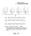
- FIG. 17 shows how the maximum value finder 12a-2 of FIG. 16 operates.
- the upper half of FIG. 17 illustrates an average power distribution of complex impulse responses at individual time positions i to k of each of four consecutive frames F1 to F4 constituting an averaging interval.
- the lower half of FIG. 17 gives a set of equations representing the averaged output signals ⁇ (i) of the average calculator 127, which are derived by applying equation (10) to the above complex impulse responses.
- the peak detector 128 seeks the maximum among ⁇ (1) to ⁇ (k). Suppose, for example, that ⁇ (2) is the largest.
- phase variations ⁇ n contains fading-induced components and frequency offset-induced components.
- Frequency offset-induced components could dominate the result of Doppler frequency estimation when they are substantially equal to or larger than fading-induced components.
- AFC automatic frequency control
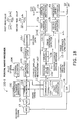
- FIG. 18 shows the structure of a modified version of the digital radio receiver 100 of the invention. Since this digital radio receiver 100-1 shares some common elements with the receiver 100 we have discussed in FIG. 13, the following explanation will not repeat the explanation for such similar elements, but concentrate on the distinctive features, while affixing like reference numerals to like elements.
- the illustrated digital radio receiver 100-1 has a data reconstructing section composed of an A/D converter 101, a synchronous channel generator 102, a frame synchronizer 103, a channel estimator 104, a synchronous detector 105, a demodulator 106, and a decoder 107.
- the digital radio receiver 100-1 comprises the following elements: a complex impulse response measurement unit 11, a phase difference calculator 12-1, a first average operator 13a, a second average operator 13b, a Doppler frequency estimator 14, a frequency offset estimator 15, a digital-to-analog (D/A) converter 16, and an AFC unit 17.
- the complex impulse response measurement unit 11 has a pilot symbol generator 11a and a correlator 11b.
- the phase difference calculator 12-1 has a maximum value finder 12a, a delay operator 12b, and a phase difference detector 12c-1.
- the phase difference detector 12c-1 calculates signed phase differences ⁇ n between complex impulse responses in consecutive frames, as well as their respective absolute values
- the first average operator 13a obtains a first mean value by averaging the absolute phase differences
- the second average operator 13b obtains a second mean value by averaging the signed phase differences ⁇ n over a plurality of frames.
- the Doppler frequency estimator 14 translates the first mean value into a Doppler frequency in units of Hz.
- the frequency offset estimator 15 translates the second mean value into a frequency offset in units of Hz, and the D/A converter 16 converts that estimate into analog form.
- the AFC unit 17 corrects the received signal to cancel the effect of frequency offset, based on the amount of the frequency offset estimate supplied through the D/A converter 16. The corrected signal is sent to the A/D converter 101.
- the communications device 10 of the present invention can be applied to receivers with an orthogonal frequency division multiplexing (OFDM) system.
- OFDM creates many orthogonal subcarriers in a given transmission band, the amplitude and phase of each subcarrier signal being varied to convey data by using digital modulation techniques such as PSK and QAM.
- the OFDM system divides a given transmission band into a number of subcarrier bands.
- the use of longer symbols with a narrower bandwidth per subcarrier mitigates inter-symbol interference (ISI) due to multipath propagation of waves, as does the addition of guard intervals.
- ISI suppression is frequency and time interleaving. Further, it is possible to minimize the distance between subcarriers by modulating all subcarriers synchronously and thus maintaining their orthogonality in the frequency domain. This feature of OFDM offers an improved spectral efficiency.
- ISDB-T terrestrial integrated services digital broadcasting
- OFDM receivers calculate a channel estimate h n,m (n: frame number, m: subcarrier number) for individual subcarriers by using pilot symbols that are multiplexed on every subcarrier channel.
- the data channel of each subcarrier is synchronously detected according to the corresponding channel estimate, and the resulting signal is then demodulated and error-corrected to reproduce the transmitted data.
- the present invention can be applied to an OFDM receiver as follows. First, channel estimates h n,m are subjected to inverse Fourier transform to yield complex impulse responses of the received signal.
- the Doppler frequency estimator of the present invention detects a maximum complex impulse response at every frame interval, calculates the absolute phase differences between consecutive frames, and averages the results over a plurality of frames. Finally, it translates the resultant mean value into an estimate of Doppler frequency.
- FIG. 19 shows the structure of an OFDM receiver.
- the illustrated OFDM receiver 200 has a data reconstructing section comprising an A/D converter 201, a synchronous channel generator 202, a frame synchronizer 203, a fast Fourier transform (FFT) processor 204, a synchronous detector 205, a demodulator 206, and a decoder 207.
- the OFDM receiver 200 contains the following elements designed according to the present invention: a complex impulse response measurement unit 21, a phase difference calculator 22, an average operator 23, and a Doppler frequency estimator 24.
- the complex impulse response measurement unit 21 has a pilot symbol generator 21a, a channel estimator 21b, and an inverse fast Fourier transform (IFFT) processor 21c.
- the phase difference calculator 22 has a maximum value finder 22a, a delay operator 22b, and a phase difference detector 22c.
- An RF signal received at an antenna (not shown) is supplied to the A/D converter 201, which converts the frequency of the received signal and performs orthogonal detection to split it into I-channel and Q-channel baseband signals.
- the A/D converter 201 converts the two signals into digital form for processing in the subsequent blocks.
- the synchronous channel generator 202 produces a replica of synchronous channel, which is to be used by the frame synchronizer 203 to detect frame timings.
- the frame synchronizer 203 examines the A/D-converted signals with reference to the synchronous channel, thus detecting the beginning of each frame contained in the signal.
- the FFT processor 204 performs Fourier transform to divide a given wideband time-domain signal into frequency-domain subcarrier signals.
- the synchronous detector 205 performs detection to reproduce the original transmission signal, while removing the effect of multipath propagation from the received signal according to estimated channel parameters.
- the demodulator 206 demodulates the modulated signal, thus reconstructing a stream of data.
- the data stream has been processed, at the sending end, with an error correction coding technique such as convolutional coding and turbo coding.
- the decoder 207 uses this error correction code to recover lost data bits, if any.
- the pilot symbol generator 21a creates pilot symbols, and the channel estimator 21b estimates channel parameters using the pilot symbols.
- the IFFT processor 21c outputs a set of complex impulse responses ⁇ n(i) in the time domain by performing the inverse Fourier transform on the estimated channel parameters of each subcarrier channel.
- the maximum value finder 22a finds a maximum complex impulse response ⁇ n among the complex impulse responses ⁇ n(i) in each frame.
- the delay operator 22b delays the detected maximum complex impulse response ⁇ n by one frame (accordingly, what appears at its output is the previous frame's maximum complex impulse response ⁇ n-1).
- the phase difference detector 22c calculates
- the average operator 23 then averages those absolute phase differences over a plurality of consecutive frames, thus obtaining a mean absolute phase difference.
- the Doppler frequency estimator 14 translates the mean value into a Doppler frequency in units of Hz. While a function to eliminate the effect of frequency offset may be implemented for more accurate Doppler frequency estimation, we omit the explanation of this variant of the OFDM receiver.
- the above-described OFDM receiver may employ an AFC function to improve its performance.
- the phase difference calculator 12-1, second average operator 13b, frequency offset estimator 15, and AFC unit 17 shown in FIG. 18 will be added to the OFDM receiver 200 of FIG. 19.
- the person skilled in the art would appreciate that such a variation is technically possible.
- phase difference calculator may actually find two or more complex impulse responses with comparable magnitudes.
- One solution in those cases is to calculate absolute phase differences at each different time position and use the average of the results in estimating Doppler frequency.
- the proposed communications device estimates the Doppler frequency by calculating complex time-domain response signals of a given propagation path in each radio frame, averaging absolute phase differences between selected complex time-domain response signals over a plurality of frames, and translating the mean absolute phase difference into an estimate of Doppler frequency.
- the communications device selectively uses multipath wave components with relatively high S/N ratios in its estimation process, thus providing an accurate estimate even in a low S/N radio environment.
- the feature of accurate Doppler frequency estimation will contribute to quality improvement in terrestrial broadcasting services.
Landscapes
- Engineering & Computer Science (AREA)
- Computer Networks & Wireless Communication (AREA)
- Signal Processing (AREA)
- Mobile Radio Communication Systems (AREA)
- Monitoring And Testing Of Transmission In General (AREA)
- Cable Transmission Systems, Equalization Of Radio And Reduction Of Echo (AREA)
Abstract
Description





Claims (32)
- A communications device for communication over wireless channels, comprising:a complex time-domain response measurement unit that obtains, at radio frame intervals, complex time-domain response signals representing characteristics of propagation paths;a phase difference calculator that calculates absolute phase differences between the complex time-domain response signals that are selected;an average operator that calculates a mean value of the absolute phase differences over a plurality of radio frames; anda Doppler frequency estimator that estimates Doppler frequency by dividing the mean value by the time length of the radio frame.
- The communications device according to claim 1, wherein said complex time-domain response measurement unit calculates the complex time-domain response signals from known pilot symbols or synchronous channel signals which are multiplexed on each radio frame.
- The communications device according to claim 1, wherein said phase difference calculator extracts a maximum complex time-domain response signal of an (n-1)th frame, identifies a time position of the extracted maximum complex time-domain response signal, and calculates an absolute phase difference between the maximum complex time-domain response signal of the (n-1)th frame and a complex time-domain response signal at the identified time position of an nth frame.
- The communications device according to claim 1, wherein said phase difference calculator selects one of the complex time-domain response signals, identifies a time position of the selected complex time-domain response signal, extracts complex time-domain response signals at the identified time position in consecutive radio frames, and calculates absolute phase differences between the extracted complex time-domain response signals.
- The communications device according to claim 1, wherein said phase difference calculator calculates average power of complex time-domain response signals at each different time position over a plurality of frames within an averaging interval, identifies a time position at which the average power hits a peak, extracts complex time-domain response signals at the identified time position in consecutive radio frames, and calculates absolute phase differences between the extracted complex time-domain response signals.
- A communications device for communication over wireless channels, comprising:a complex time-domain response measurement unit that obtains complex time-domain response signals from a received signal at radio frame intervals, the complex time-domain response signals representing characteristics of propagation paths, the received signal being affected by a frequency offset;a phase difference calculator that calculates signed phase differences and absolute phase differences between the complex time-domain response signals that are selected;a first average operator that obtains a first mean value by averaging the absolute phase differences over a plurality of radio frames;a second average operator that obtains a second mean value by averaging the signed phase differences over the plurality of radio frames;a frequency offset estimator that estimates the frequency offset by dividing the second mean value by the time length of the radio frame;an automatic frequency control (AFC) unit that reduces effects of the frequency offset, based on the estimated frequency offset; anda Doppler frequency estimator that estimates Doppler frequency by dividing the first mean value by the time length of the radio frame.
- The communications device according to claim 6, wherein said complex time-domain response measurement unit calculates the complex time-domain response signals from known pilot symbols or synchronous channel signals which are multiplexed on each radio frame.
- The communications device according to claim 6, wherein said phase difference calculator extracts a maximum complex time-domain response signal of an (n-1)th frame, identifies a time position of the extracted maximum complex time-domain response signal, and calculates a signed phase difference and an absolute phase difference between the maximum complex time-domain response signal of the (n-1) th frame and a complex time-domain response signal at the identified time position of an nth frame.
- The communications device according to claim 6, wherein said phase difference calculator selects one of the complex time-domain response signals, identifies a time position of the selected complex time-domain response signal, extracts complex time-domain response signals at the identified time position in consecutive radio frames, and calculates signed phase differences and absolute phase differences between the extracted complex time-domain response signals.
- The communications device according to claim 6, wherein said phase difference calculator calculates average power of complex time-domain response signals at each different time position over a plurality of frames within an averaging interval, identifies a time position at which the average power hits a peak, extracts complex time-domain response signals at the identified time position in consecutive radio frames, and calculates signed phase differences and absolute phase differences between the extracted complex time-domain response signals.
- An orthogonal frequency division multiplexing (OFDM) receiver that receives an OFDM-modulated signal, comprising:a complex time-domain response measurement unit that estimates subcarrier channels for each radio frame and obtains complex time-domain response signals by performing inverse Fourier transform on all the subcarrier channel estimates;a phase difference calculator that calculates absolute phase differences between the complex time-domain response signals that are selected;an average operator that calculates a mean value of the absolute phase differences over a plurality of radio frames; anda Doppler frequency estimator that estimates Doppler frequency by dividing the mean value by the time length of the radio frame.
- The OFDM receiver according to claim 11, wherein said complex time-domain response measurement unit calculates the complex time-domain response signals from known pilot symbols or synchronous channel signals which are multiplexed on each radio frame.
- The OFDM receiver according to claim 11, wherein said phase difference calculator extracts a maximum complex time-domain response signal of an (n-1)th frame, identifies a time position of the extracted maximum complex time-domain response signal, and calculates an absolute phase difference between the maximum complex time-domain response signal of the (n-1)th frame and a complex time-domain response signal at the identified time position of an nth frame.
- The OFDM receiver according to claim 11, wherein said phase difference calculator selects one of the complex time-domain response signals, identifies a time position of the selected complex time-domain response signal, extracts complex time-domain response signals at the identified time position in consecutive radio frames, and calculates absolute phase differences between the extracted complex time-domain response signals.
- The OFDM receiver according to claim 11, wherein said phase difference calculator calculates average power of complex time-domain response signals at each different time position over a plurality of frames within an averaging interval, identifies a time position at which the average power hits a peak, extracts complex time-domain response signals at the identified time position in consecutive radio frames, and calculates absolute phase differences between the extracted complex time-domain response signals.
- An orthogonal frequency division multiplexing (OFDM) receiver that receives an OFDM-modulated signal, comprising:a complex time-domain response measurement unit that estimates subcarrier channels for each radio frame of a received signal and obtains complex time-domain response signals by performing inverse Fourier transform on all the subcarrier channel estimates, the received signal being affected by a frequency offset;a phase difference calculator that calculates signed phase differences and absolute phase differences between the complex time-domain response signals that are selected;a first average operator that obtains a first mean value by averaging the absolute phase differences over a plurality of radio frames;a second average operator that obtains a second mean value by averaging the signed phase differences over the plurality of radio frames;a frequency offset estimator that estimates the frequency offset by dividing the second mean value by the time length of the radio frame;an automatic frequency control (AFC) unit that reduces effects of the frequency offset, based on the estimated frequency offset; anda Doppler frequency estimator that estimates Doppler frequency by dividing the first mean value by the time length of the radio frame.
- The OFDM receiver according to claim 16, wherein said complex time-domain response measurement unit calculates the complex time-domain response signals from known pilot symbols or synchronous channel signals which are multiplexed on each radio frame.
- The OFDM receiver according to claim 16, wherein said phase difference calculator extracts a maximum complex time-domain response signal of an (n-1)th frame, identifies a time position of the extracted maximum complex time-domain response signal, and calculates a signed phase difference and an absolute phase difference between the maximum complex time-domain response signal of the (n-1)th frame and a complex time-domain response signal at the identified time position of an nth frame.
- The OFDM receiver according to claim 16, wherein said phase difference calculator selects one of the complex time-domain response signals, identifies a time position of the selected complex time-domain response signal, extracts complex time-domain response signals at the identified time position in consecutive radio frames, and calculates signed phase differences and absolute phase differences between the extracted complex time-domain response signals.
- The OFDM receiver according to claim 16, wherein said phase difference calculator calculates average power of complex time-domain response signals at each different time position over a plurality of frames within an averaging interval, identifies a time position at which the average power hits a peak, extracts complex time-domain response signals at the identified time position in consecutive radio frames, and calculates signed phase differences and absolute phase differences between the extracted complex time-domain response signals.
- A method of estimating Doppler frequency that occurs in proportion to speed of a mobile station, the method comprising the steps of:(a) obtaining, at radio frame intervals, complex time-domain response signals representing characteristics of propagation paths;(b) calculating absolute phase differences between the complex time-domain response signals that are selected;(c) calculating a mean value of the absolute phase differences over a plurality of radio frames; and(d) estimating Doppler frequency by dividing the mean value by the time length of the radio frame.
- The method according to claim 21, wherein said signal obtaining step (a) calculates the complex time-domain response signals from known pilot symbols or synchronous channel signals which are multiplexed on each radio frame.
- The method according to claim 21, wherein said difference calculating step (b) comprises the substeps of:extracting a maximum complex time-domain response signal of an (n-1)th frame;identifying a time position of the extracted maximum complex time-domain response signal; andcalculating an absolute phase difference between the maximum complex time-domain response signal of the (n-1)th frame and a complex time-domain response signal at the identified time position of an nth frame.
- The method according to claim 21, wherein said difference calculating step (b) comprises the substeps of:selecting one of the complex time-domain response signals;identifying a time position of the selected complex time-domain response signal;extracting complex time-domain response signals at the identified time position in consecutive radio frames; andcalculating absolute phase differences between the extracted complex time-domain response signals.
- The method according to claim 21, wherein said difference calculating step (b) comprises the substeps of:calculating average power of complex time-domain response signals at each different time position over a plurality of frames within an averaging interval;identifying a time position at which the average power hits a peak;extracting complex time-domain response signals at the identified time position in consecutive radio frames; andcalculating absolute phase differences between the extracted complex time-domain response signals.
- The method according to claim 21, wherein:the mobile station receives an OFDM-modulated signal; andsaid signal obtaining step (a) comprises the substeps of:estimating subcarrier channels for each radio frame, andobtaining complex time-domain response signals by performing inverse Fourier transform on all the subcarrier channel estimates.
- A method of estimating Doppler frequency that occurs in proportion to speed of a mobile station, the method comprising the steps of:(a) obtaining complex time-domain response signals from a received signal at radio frame intervals, the complex time-domain response signals representing characteristics of propagation paths, the received signal being affected by a frequency offset;(b) calculating signed phase differences and absolute phase differences between the complex time-domain response signals that are selected;(c) obtaining a first mean value by averaging the absolute phase differences over a plurality of radio frames;(d) obtaining a second mean value by averaging the signed phase differences over the plurality of radio frames;(e) estimating the frequency offset by dividing the second mean value by the time length of the radio frame;(f) reducing effects of the frequency offset, based on the estimated frequency offset; and(g) estimating Doppler frequency by dividing the first mean value by the time length of the radio frame.
- The method according to claim 27, wherein said signal obtaining step (a) calculates the complex time-domain response signals from known pilot symbols or synchronous channel signals which are multiplexed on each radio frame.
- The method according to claim 27, wherein said difference calculating step (b) comprises the substeps of:extracting a maximum complex time-domain response signal of an (n-1)th frame;identifying a time position of the extracted maximum complex time-domain response signal; andcalculating a signed phase difference and an absolute phase difference between the maximum complex time-domain response signal of the (n-1) th frame and a complex time-domain response signal at the identified time position of an nth frame.
- The method according to claim 27, wherein said difference calculating step (b) comprises the substeps of:selecting one of the complex time-domain response signals;identifying a time position of the selected complex time-domain response signal;extracting complex time-domain response signals at the identified time position in consecutive radio frames; andcalculating signed phase differences and absolute phase differences between the extracted complex time-domain response signals.
- The method according to claim 27, wherein said difference calculating step (b) comprises the substeps of:calculating average power of complex time-domain response signals at each different time position over a plurality of frames within an averaging interval;identifying a time position at which the average power hits a peak;extracting complex time-domain response signals at the identified time position in consecutive radio frames; andcalculating signed phase differences and absolute phase differences between the extracted complex time-domain response signals.
- The method according to claim 27, wherein:the mobile station receives an OFDM-modulated signal; andsaid signal obtaining step (a) comprises the substeps of:estimating subcarrier channels for each radio frame, andobtaining complex time-domain response signals by performing inverse Fourier transform on all the subcarrier channel estimates.
Applications Claiming Priority (4)
| Application Number | Priority Date | Filing Date | Title |
|---|---|---|---|
| JP2003044509 | 2003-02-21 | ||
| JP2003044509 | 2003-02-21 | ||
| JP2004001794 | 2004-01-07 | ||
| JP2004001794A JP4338532B2 (en) | 2003-02-21 | 2004-01-07 | Communication device |
Publications (3)
| Publication Number | Publication Date |
|---|---|
| EP1450497A2 true EP1450497A2 (en) | 2004-08-25 |
| EP1450497A3 EP1450497A3 (en) | 2004-12-08 |
| EP1450497B1 EP1450497B1 (en) | 2007-10-24 |
Family
ID=32737744
Family Applications (1)
| Application Number | Title | Priority Date | Filing Date |
|---|---|---|---|
| EP20040003841 Expired - Lifetime EP1450497B1 (en) | 2003-02-21 | 2004-02-20 | Communications device with Doppler frequency estimation functions |
Country Status (4)
| Country | Link |
|---|---|
| US (1) | US7349483B2 (en) |
| EP (1) | EP1450497B1 (en) |
| JP (1) | JP4338532B2 (en) |
| DE (1) | DE602004009625T2 (en) |
Cited By (5)
| Publication number | Priority date | Publication date | Assignee | Title |
|---|---|---|---|---|
| EP2009810A1 (en) * | 2007-06-29 | 2008-12-31 | Nokia Siemens Networks Oy | Method and device for data communication system comprising such device |
| US7599453B2 (en) | 2005-04-21 | 2009-10-06 | Telefonaktiebolaget L M Ericsson (Publ) | Doppler spread estimation for OFDM systems |
| US7627047B2 (en) * | 2004-11-30 | 2009-12-01 | Kabushiki Kaisha Toshiba | Orthogonal frequency division multiplexing (OFDM) receiver |
| CN106341357A (en) * | 2015-07-07 | 2017-01-18 | 中国移动通信集团公司 | Downlink frequency deviation compensation method and device |
| CN118249842A (en) * | 2024-03-20 | 2024-06-25 | 电子科技大学 | Channel equalization synchronization method for time-hopping frequency-hopping communication |
Families Citing this family (39)
| Publication number | Priority date | Publication date | Assignee | Title |
|---|---|---|---|---|
| JP4228014B2 (en) * | 2004-04-05 | 2009-02-25 | パナソニック株式会社 | Wireless communication apparatus and wireless communication method |
| KR100643740B1 (en) * | 2004-04-09 | 2006-11-10 | 삼성전자주식회사 | Apparatus and method for pilot code pattern transmission / reception for base station classification in communication system using orthogonal frequency division multiplexing |
| KR100630196B1 (en) * | 2004-11-15 | 2006-09-29 | 삼성전자주식회사 | Synchronization Acquisition Apparatus and Method in Mobile Communication System Using Orthogonal Frequency Division Multiplexing |
| CN1317830C (en) * | 2005-04-15 | 2007-05-23 | 展讯通信(上海)有限公司 | Auto frequency deviation correcting method and its apparatus and receiver of using same method |
| JP2006352746A (en) * | 2005-06-20 | 2006-12-28 | Fujitsu Ltd | Receiver for orthogonal frequency division multiplex transmission |
| FI20050713A0 (en) * | 2005-07-04 | 2005-07-04 | Nokia Corp | A speed detection method in a communication system, a receiver, a network element, and a processor |
| JP4510712B2 (en) * | 2005-07-15 | 2010-07-28 | シャープ株式会社 | Multi-carrier signal receiver and multi-carrier signal receiving method |
| EP1750379A1 (en) * | 2005-08-04 | 2007-02-07 | Nortel Networks Limited | Method and apparatus for estimation of a frequency offset due to the Doppler effect |
| JP2007214750A (en) * | 2006-02-08 | 2007-08-23 | Nec Corp | Radio receiver and method for correcting noise estimation value |
| US7912139B2 (en) * | 2006-04-03 | 2011-03-22 | Panasonic Corporation | Multi-carrier communication apparatus, power line communication circuit, and multi-carrier communication method |
| JP4748678B2 (en) * | 2006-05-18 | 2011-08-17 | Kddi株式会社 | Radio apparatus, program and communication method for adaptively changing pilot signal arrangement |
| KR101100791B1 (en) * | 2006-10-16 | 2012-01-02 | 닛본 덴끼 가부시끼가이샤 | Receiving method and receiving device |
| JP4328812B2 (en) * | 2006-10-23 | 2009-09-09 | Okiセミコンダクタ株式会社 | Scattered pilot placement detector |
| US7856066B2 (en) * | 2006-10-27 | 2010-12-21 | Oki Semiconductor Co., Ltd. | OFDM receiver and doppler frequency estimating circuit |
| JP5073433B2 (en) * | 2007-02-22 | 2012-11-14 | ラピスセミコンダクタ株式会社 | OFDM receiver |
| US20080151980A1 (en) * | 2006-12-22 | 2008-06-26 | Bengt Lindoff | Method of and apparatus for adaptive frequency error estimation |
| JP5027595B2 (en) * | 2007-08-21 | 2012-09-19 | 日本無線株式会社 | OFDM demodulator and relay broadcast apparatus |
| US7844006B2 (en) * | 2007-09-11 | 2010-11-30 | Massachusetts Institute Of Technology | Method of non-uniform doppler compensation for wideband orthogonal frequency division multiplexed signals |
| US8081673B2 (en) * | 2007-11-30 | 2011-12-20 | Cellnet Innovations, Inc. | Systems and methods for processing spread spectrum signals |
| US8107551B2 (en) * | 2007-12-14 | 2012-01-31 | Cellnet Innovations, Inc. | Systems and methods for signal modulation and demodulation using phase |
| JP5115340B2 (en) * | 2008-06-09 | 2013-01-09 | 富士通株式会社 | Wireless communication apparatus and frequency deviation calculation method |
| JP5109878B2 (en) * | 2008-09-03 | 2012-12-26 | 富士通株式会社 | Demodulator |
| JP4774435B2 (en) * | 2008-11-21 | 2011-09-14 | 株式会社半導体理工学研究センター | Doppler frequency estimation device, receiving device, program, and Doppler frequency estimation method |
| CN101771434A (en) * | 2008-12-26 | 2010-07-07 | 中兴通讯股份有限公司 | Method for adjusting frequency deviation of mobile terminal and device thereof |
| JP5155254B2 (en) * | 2009-06-15 | 2013-03-06 | 富士通株式会社 | Semiconductor integrated circuit and received signal processing method |
| KR101579984B1 (en) * | 2009-10-22 | 2016-01-04 | 삼성전자주식회사 | method and apparatus for recovering estimated velocity of mobile terminal |
| KR101643419B1 (en) * | 2009-12-24 | 2016-07-27 | 삼성전자주식회사 | Method and apparatus for estimating a channel using phase compensation in a wireless communication system |
| US9031122B2 (en) * | 2010-01-29 | 2015-05-12 | Qualcomm Incorporated | Reducing phase errors on a communication device |
| JP5865172B2 (en) * | 2012-05-09 | 2016-02-17 | 富士通株式会社 | Receiving apparatus and receiving method |
| US9635501B2 (en) * | 2013-12-23 | 2017-04-25 | Microsemi Frequency And Time Corporation | Method and system for synchronizing base station and establishing location |
| US10802129B2 (en) * | 2015-02-17 | 2020-10-13 | Lg Electronics Inc. | Doppler measurement method in wireless LAN system |
| WO2016153265A1 (en) * | 2015-03-26 | 2016-09-29 | 엘지전자 주식회사 | Method and device for estimating doppler frequency by using beam scanning process in wireless communication system |
| CN105024878B (en) * | 2015-06-30 | 2018-07-20 | 芯海科技(深圳)股份有限公司 | A kind of time-delay measuring method of OFDM group systems |
| CN106027116B (en) * | 2016-07-07 | 2018-08-31 | 哈尔滨工程大学 | A kind of mobile underwater sound communication Doppler coefficient method of estimation based on chirp signals |
| WO2019052685A1 (en) * | 2017-09-15 | 2019-03-21 | Metirionic Gmbh | METHOD FOR RADIO MEASUREMENT APPLICATIONS |
| WO2020026266A1 (en) * | 2018-07-28 | 2020-02-06 | Wisig Networks Private Limited | Method and system for classifying speed of a user equipment |
| US11777763B2 (en) * | 2020-03-20 | 2023-10-03 | Nantworks, LLC | Selecting a signal phase in a communication system |
| US12088370B2 (en) * | 2022-09-27 | 2024-09-10 | Qualcomm Incorporated | Parallel shift estimation for LOS MIMO communication |
| JP7730349B2 (en) * | 2023-05-24 | 2025-08-27 | アンリツ株式会社 | Test system and maximum Doppler frequency calculation method |
Family Cites Families (14)
| Publication number | Priority date | Publication date | Assignee | Title |
|---|---|---|---|---|
| JP2840864B2 (en) * | 1989-11-13 | 1998-12-24 | 株式会社日立メディコ | Pulse Doppler measurement device |
| US5272446A (en) * | 1991-11-29 | 1993-12-21 | Comsat | Digitally implemented fast frequency estimator/demodulator for low bit rate maritime and mobile data communications without the use of an acquisition preamble |
| FR2685839A1 (en) | 1991-12-26 | 1993-07-02 | Thomson Csf | METHOD FOR COHERENT MODULATION AND DEMODULATION FOR TRANSMITTING HIGH FREQUENCY HF DATA. |
| JPH1065610A (en) | 1996-08-22 | 1998-03-06 | Oki Electric Ind Co Ltd | Mobile radio communication equipment |
| US6058101A (en) * | 1997-06-11 | 2000-05-02 | Industrial Technology Research Institute | Synchronization method and system for a digital receiver |
| JP3323453B2 (en) * | 1999-02-09 | 2002-09-09 | 松下電器産業株式会社 | CDMA receiving apparatus and CDMA receiving method |
| DE69923541T2 (en) | 1999-05-10 | 2006-02-16 | Lucent Technologies Inc. | A method of determining the speed of a mobile station in a cellular communication system |
| JP3910443B2 (en) * | 1999-06-09 | 2007-04-25 | 三菱電機株式会社 | Automatic frequency controller |
| JP2001016135A (en) * | 1999-06-29 | 2001-01-19 | Nec Corp | Method and system for automatically controlling frequency and cdma receiver |
| CN1350729A (en) | 2000-03-31 | 2002-05-22 | 三菱电机株式会社 | Method and apparatus for automatically controlling frequency and demodulation device |
| EP1148659B1 (en) * | 2000-04-18 | 2005-07-27 | Sony International (Europe) GmbH | OFDM diversity transmission |
| US7123670B2 (en) * | 2001-09-24 | 2006-10-17 | Atheros Communications, Inc. | Fine frequency offset estimation and calculation and use to improve communication system performance |
| JP3877158B2 (en) * | 2002-10-31 | 2007-02-07 | ソニー・エリクソン・モバイルコミュニケーションズ株式会社 | Frequency deviation detection circuit, frequency deviation detection method, and portable communication terminal |
| US7164737B2 (en) * | 2002-12-20 | 2007-01-16 | Lg Electronics Inc. | Method for estimating doppler frequency |
-
2004
- 2004-01-07 JP JP2004001794A patent/JP4338532B2/en not_active Expired - Fee Related
- 2004-02-20 DE DE200460009625 patent/DE602004009625T2/en not_active Expired - Lifetime
- 2004-02-20 US US10/783,791 patent/US7349483B2/en not_active Expired - Fee Related
- 2004-02-20 EP EP20040003841 patent/EP1450497B1/en not_active Expired - Lifetime
Cited By (7)
| Publication number | Priority date | Publication date | Assignee | Title |
|---|---|---|---|---|
| US7627047B2 (en) * | 2004-11-30 | 2009-12-01 | Kabushiki Kaisha Toshiba | Orthogonal frequency division multiplexing (OFDM) receiver |
| US7599453B2 (en) | 2005-04-21 | 2009-10-06 | Telefonaktiebolaget L M Ericsson (Publ) | Doppler spread estimation for OFDM systems |
| EP2009810A1 (en) * | 2007-06-29 | 2008-12-31 | Nokia Siemens Networks Oy | Method and device for data communication system comprising such device |
| WO2009003852A1 (en) * | 2007-06-29 | 2009-01-08 | Nokia Siemens Networks Oy | Method and device for data communication and communication system comprising such device |
| CN106341357A (en) * | 2015-07-07 | 2017-01-18 | 中国移动通信集团公司 | Downlink frequency deviation compensation method and device |
| CN106341357B (en) * | 2015-07-07 | 2020-04-03 | 中国移动通信集团公司 | A kind of downlink frequency offset compensation method and device |
| CN118249842A (en) * | 2024-03-20 | 2024-06-25 | 电子科技大学 | Channel equalization synchronization method for time-hopping frequency-hopping communication |
Also Published As
| Publication number | Publication date |
|---|---|
| DE602004009625T2 (en) | 2008-08-28 |
| JP2004274722A (en) | 2004-09-30 |
| EP1450497B1 (en) | 2007-10-24 |
| US20040190657A1 (en) | 2004-09-30 |
| DE602004009625D1 (en) | 2007-12-06 |
| JP4338532B2 (en) | 2009-10-07 |
| US7349483B2 (en) | 2008-03-25 |
| EP1450497A3 (en) | 2004-12-08 |
Similar Documents
| Publication | Publication Date | Title |
|---|---|---|
| EP1450497B1 (en) | Communications device with Doppler frequency estimation functions | |
| Kim et al. | An efficient frequency offset estimator for OFDM systems and its performance characteristics | |
| US7336597B2 (en) | System and method for two channel frequency offset estimation of OFDM signals | |
| US8351534B2 (en) | Distributed maximal ratio combining receiver architecture | |
| JP5546358B2 (en) | Data processing apparatus and data processing method | |
| JP5221518B2 (en) | Method and apparatus for clock correction in MIMO OFDM | |
| US8625684B2 (en) | Apparatus and method for estimating symbol timing offset in a wireless communication system | |
| US20040190560A1 (en) | Receiver and method to detect and synchronize with a symbol boundary of an OFDM symbol | |
| Alexander et al. | Outdoor mobile broadband access with 802.11 | |
| EP1253733A1 (en) | Radio transmitting apparatus and radio transmitting method | |
| JP2015029164A (en) | Diversity receiver | |
| KR20070068821A (en) | Apparatus and Method for Estimating Initial Carrier Frequency Offset in Orthogonal Frequency Division Multiplexing Receiver | |
| Czylwik | Low overhead pilot-aided synchronization for single carrier modulation with frequency domain equalization | |
| US20060198472A1 (en) | Transmission system, transmitter device, and receiver device | |
| JP3544147B2 (en) | OFDM signal receiving apparatus, OFDM signal communication system and communication control method therefor | |
| JP2005286362A (en) | Digital receiver | |
| JP5175253B2 (en) | Single carrier receiver | |
| JP2000022660A (en) | Digital communication device | |
| JP2007019985A (en) | Receiver | |
| JP3793198B2 (en) | OFDM signal communication system and OFDM signal transmitter | |
| Chen et al. | Baseband transceiver design for the DVB-terrestrial standard | |
| Tufvesson et al. | Preamble-based time and frequency synchronization for OFDM systems | |
| WO2007067018A1 (en) | Apparatus for estimating time and frequency offset using antenna diversity in ofdm communication system and method thereof | |
| Liang et al. | On the spectral bitrate loss of superimposed pilot and preamble synchronization | |
| Arslan et al. | Measurement-based WiMAX transceiver design and performance evaluation |
Legal Events
| Date | Code | Title | Description |
|---|---|---|---|
| PUAI | Public reference made under article 153(3) epc to a published international application that has entered the european phase |
Free format text: ORIGINAL CODE: 0009012 |
|
| AK | Designated contracting states |
Kind code of ref document: A2 Designated state(s): AT BE BG CH CY CZ DE DK EE ES FI FR GB GR HU IE IT LI LU MC NL PT RO SE SI SK TR |
|
| AX | Request for extension of the european patent |
Extension state: AL LT LV MK |
|
| PUAL | Search report despatched |
Free format text: ORIGINAL CODE: 0009013 |
|
| AK | Designated contracting states |
Kind code of ref document: A3 Designated state(s): AT BE BG CH CY CZ DE DK EE ES FI FR GB GR HU IE IT LI LU MC NL PT RO SE SI SK TR |
|
| AX | Request for extension of the european patent |
Extension state: AL LT LV MK |
|
| 17P | Request for examination filed |
Effective date: 20041206 |
|
| AKX | Designation fees paid |
Designated state(s): DE FR GB |
|
| 17Q | First examination report despatched |
Effective date: 20060823 |
|
| GRAP | Despatch of communication of intention to grant a patent |
Free format text: ORIGINAL CODE: EPIDOSNIGR1 |
|
| GRAS | Grant fee paid |
Free format text: ORIGINAL CODE: EPIDOSNIGR3 |
|
| GRAA | (expected) grant |
Free format text: ORIGINAL CODE: 0009210 |
|
| AK | Designated contracting states |
Kind code of ref document: B1 Designated state(s): DE FR GB |
|
| REG | Reference to a national code |
Ref country code: GB Ref legal event code: FG4D |
|
| REF | Corresponds to: |
Ref document number: 602004009625 Country of ref document: DE Date of ref document: 20071206 Kind code of ref document: P |
|
| ET | Fr: translation filed | ||
| PLBE | No opposition filed within time limit |
Free format text: ORIGINAL CODE: 0009261 |
|
| STAA | Information on the status of an ep patent application or granted ep patent |
Free format text: STATUS: NO OPPOSITION FILED WITHIN TIME LIMIT |
|
| 26N | No opposition filed |
Effective date: 20080725 |
|
| PGFP | Annual fee paid to national office [announced via postgrant information from national office to epo] |
Ref country code: FR Payment date: 20110218 Year of fee payment: 8 Ref country code: DE Payment date: 20110216 Year of fee payment: 8 |
|
| PGFP | Annual fee paid to national office [announced via postgrant information from national office to epo] |
Ref country code: GB Payment date: 20110216 Year of fee payment: 8 |
|
| GBPC | Gb: european patent ceased through non-payment of renewal fee |
Effective date: 20120220 |
|
| REG | Reference to a national code |
Ref country code: FR Ref legal event code: ST Effective date: 20121031 |
|
| REG | Reference to a national code |
Ref country code: DE Ref legal event code: R119 Ref document number: 602004009625 Country of ref document: DE Effective date: 20120901 |
|
| PG25 | Lapsed in a contracting state [announced via postgrant information from national office to epo] |
Ref country code: FR Free format text: LAPSE BECAUSE OF NON-PAYMENT OF DUE FEES Effective date: 20120229 Ref country code: GB Free format text: LAPSE BECAUSE OF NON-PAYMENT OF DUE FEES Effective date: 20120220 |
|
| PG25 | Lapsed in a contracting state [announced via postgrant information from national office to epo] |
Ref country code: DE Free format text: LAPSE BECAUSE OF NON-PAYMENT OF DUE FEES Effective date: 20120901 |