EP1450247A1 - Mensch-Rechner Schnittstelle mit Kraftrückkoppelung für druckempfindliche Eingabetafel - Google Patents
Mensch-Rechner Schnittstelle mit Kraftrückkoppelung für druckempfindliche Eingabetafel Download PDFInfo
- Publication number
- EP1450247A1 EP1450247A1 EP04290435A EP04290435A EP1450247A1 EP 1450247 A1 EP1450247 A1 EP 1450247A1 EP 04290435 A EP04290435 A EP 04290435A EP 04290435 A EP04290435 A EP 04290435A EP 1450247 A1 EP1450247 A1 EP 1450247A1
- Authority
- EP
- European Patent Office
- Prior art keywords
- touch screen
- analysis
- man
- interface device
- machine interface
- Prior art date
- Legal status (The legal status is an assumption and is not a legal conclusion. Google has not performed a legal analysis and makes no representation as to the accuracy of the status listed.)
- Granted
Links
Images


Classifications
-
- G—PHYSICS
- G06—COMPUTING; CALCULATING OR COUNTING
- G06F—ELECTRIC DIGITAL DATA PROCESSING
- G06F3/00—Input arrangements for transferring data to be processed into a form capable of being handled by the computer; Output arrangements for transferring data from processing unit to output unit, e.g. interface arrangements
- G06F3/01—Input arrangements or combined input and output arrangements for interaction between user and computer
- G06F3/016—Input arrangements with force or tactile feedback as computer generated output to the user
-
- G—PHYSICS
- G06—COMPUTING; CALCULATING OR COUNTING
- G06F—ELECTRIC DIGITAL DATA PROCESSING
- G06F3/00—Input arrangements for transferring data to be processed into a form capable of being handled by the computer; Output arrangements for transferring data from processing unit to output unit, e.g. interface arrangements
- G06F3/01—Input arrangements or combined input and output arrangements for interaction between user and computer
- G06F3/03—Arrangements for converting the position or the displacement of a member into a coded form
- G06F3/041—Digitisers, e.g. for touch screens or touch pads, characterised by the transducing means
Definitions
- the technical sector of the present invention is that human-machine interfaces, and more particularly those using touchscreens with or without return visual.
- the problem dealt with by the present invention concerns more particularly the use of devices of the type touch screen in a disturbed environment in terms of vibrations and shocks such as control stations on board vehicles.
- the object of the present invention is to provide the operator of a device incorporating a type interface touchscreen, a modal interaction of human touch, under form of force feedback.
- This return of effort can take at least two types of forms: it can be of the type "Vibrational sensation" or of the "tactile effect” type.
- biomechanical effects allow, by their presence, instant feedback when pressed digital on the touch screen. These biomechanical effects, by their differentiation, allow more interpretation by the operator of the current operating mode.
- This additional touch mode interaction human improves and secures the interaction of the man with the device, possibly getting rid of visual interaction, and allows various uses, including understood in environments where the operator is potentially disturbed by shock or vibration.
- Such a device can, like a conventional touch screen be supplemented secondarily by a display screen on which the transparent touch screen is superimposed. This is to complete the multimodal interaction, with visual type information.
- Tactile tiles of different types are known to this day kinds.
- Such devices are used for pointing and provide the location of the finger contact of the operator in coordinates, generally Cartesian, X and Y.
- the operator can designate a point over the entire surface of the touch screen.
- the processing and analysis unit is responsible for locating the exact position of the contact.
- the visual mode thanks to the superposition of the touch screen, above a display screen, the touch screen being generally made transparent. This requires direct vision from the operator and display screen and its supporting action on the touch screen. The operator is informed of the result of its action on the touch screen, by a modification of the image presented on the viewing screen located under the touch screen and visible in transparency, to ensure the correspondence between the tactile action and the return visual information.
- On-board human machine interface applications on board vehicles for example, generating many movements which could disturb the operator during his interactions, ask to combine on the same screen, tactile keys, pointing zones, prohibited zones at the supports. These applications are further complicated when these zones evolve dynamically over time as a function interactions and are no longer just static. It is the case for example of a drop-down menu application, or interactive applications between multiple diagrams of viewing. The combination of these typologies of areas touch requires ergonomic perception and a level of security for operator actions.
- the present invention remedies these various disadvantages.
- the device which is the subject of the present invention consists, in animating the touch screen with a movement, which can be modulated, both in amplitude and in frequency, and both as a function of time as a function of the operator's support force on this same touch screen, to be transmitted to the finger of the operator, biomechanical force feedback in the form detectable by the sense of human touch, in response instantaneous contact of said finger with said slab Touch.
- a means of setting in motion is fixed on the one hand to a touch screen and on the other hand, to a body considered to be immobile, thus allowing to animate the touch screen with a movement detectable by the touch of an operator.
- a means pressure analysis is fixed on the one hand to a slab touch and on the other hand to a housing body considered immobile, thus making it possible to measure the pressure during operator support on this touch screen.
- the means for setting in motion the touch screen can, for example, be at least one actuator preferably mounted on the periphery of the touch screen.
- the means analysis of the pressure exerted on the touch screen can, for example, be at least one sensor preferably mounted on the periphery of the touch screen.
- the means of movement and the means of pressure analysis can be confused.
- the means of motion and pressure analysis can advantageously be made on the basis of an electromagnet.
- the displacement of the touch screen can be amplitude modulated and in frequency as a function of time and / or as a function of the pressure measured.
- This modulation is controlled by the unit analysis and processing that allows for different displacement reasons.
- the analysis and processing unit also analyzes the data measured by the measurement means pressure.
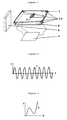
- a pattern of displacement can, by way of illustration, be a displacement of periodic amplitude as a function of time (according to the curve type A), to produce a "vibrational sensation".
- a pattern of displacement can, by way of illustration, be a displacement amplitude as a function of pressure (according to the type B curve), to produce a "tactile effect” or "tactile click".
- the unit analysis and processing ensures the control of the slab touch and determines the X and Y coordinates of the position of operator support.
- This analysis and processing unit can be configured to react, when operator presses in defined support zones, by a given pattern of moving the touch screen.
- the assembly of the touch device can be positioned in front of a screen visualization in order to complete the tactile information by visual information.
- the device which is the subject of the present invention, such as the shows figure 1, includes main components following: a sensitive touch screen 1, a means of setting movement 2 of said touch screen 1, a means of analysis of the pressure 3 exerted on said touch screen 1, a unit processing and analysis 4, a housing body 5.
- a sensitive touch screen 1 a means of setting movement 2 of said touch screen 1
- a means of analysis of the pressure 3 exerted on said touch screen 1 a unit processing and analysis 4
- a housing body 5 We can complete the device with a display screen 6.
- Touchscreen 1 is a classic touchscreen of any technology. When you press or touch its flat surface, this support is detected and the X coordinates and Y of the fulcrum are determined by the unit of processing and analysis 4. The operator can touch the slab touch 1 at any point on its surface. The processing unit and analysis 4 is responsible for locating the exact position.
- the moving means 2 is fixed between the body of housing 5 and the touch screen 1, which it connects one to the other. It allows by its internal deformation a displacement relative of the touch screen 1 with respect to the housing body 5.
- the function of the moving means 2 consists in vary as a function of time the distance between its point of attachment to touchscreen 1 and its attachment point on the housing body 5. This can be achieved by deformation of the means of movement 2.
- the man of profession knows actuators capable of this function. This thus produces a displacement of the touch screen 1 relative to the housing body 5.
- the pressure analysis means 3 is mounted between the housing body 5 and the touch screen 1.
- the function of the pressure analysis means 3 is to measure the pressure exerted on the touchscreen 1, for example, by analysis of its own deformation. This pressure measured at level of the pressure analysis means 3 is representative the support force exerted by the operator on the slab touch 1.
- the displacement of the touch screen 1 relative to the housing body 5 imposed by the moving means 2 is controlled by the processing and analysis unit 4.
- This analysis and processing unit 4 is connected on the one hand by means of setting in motion 2 and on the other hand by means of pressure analysis 3.
- the displacement thus produced can be modulated in amplitude and / or frequency as a function of time or function of the pressure analyzed by the means of analysis of the pressure 3 and which is indicative of the pressing force exerted by the operator on the touch screen 1.
- the processing and analysis unit 4 is capable enslavement and can therefore produce different patterns of moving the touchscreen 1.
- two motifs of displacement the “vibrational sensation” motif and the motif "Tactile effect”.
- the “vibrational sensation” motif has the function of provide operator feedback detectable by the sense of touch when pressing on touchscreen 1.
- This pattern is obtained by modulating the displacement produced by the moving means 2 according to an amplitude modulation periodic as a function of time, according to a type A curve.
- FIG. 2 gives an example of a curve, of type A, Displacement (D) as a function of Time (T).
- D Displacement
- T Time
- Such displacement has the effect of producing a vibration of the touch screen 1 clearly visible to the operator when touched press the touchscreen 1.
- This can, for example example, confirm to the operator that his support action by the processing and analysis unit 4.
- the two parameters amplitude and frequency can be adjustable and variable and go determine different qualities of sensation of vibration. This allows flexible perceptions understandable and discriminable by the sense of touch.
- the device object of the present invention is not limited not to the two motives "vibrational sensation” and “effect touch screen "as described above, which are not illustrative of the possibilities of the invention. It is possible to use other combined patterns in vibrational frequency, in time sequence, indeed Touch.
- the means of setting in motion 2 and the means of analyzing pressure 3 can be confused in the same organ capable of both actuator and sensor functions.
- a particular achievement consists in using an electromagnet at each corner of a rectangular touch screen, each of these electromagnets being used as an actuator in motion and as a pressure sensor.
- Figure 4 illustrates the principle of Ampère's law applied to an electromagnet.
- An electric current I crossing a coil B creates an electric field E and a magnetic field H.
- An actuator A located in the axis of the coil B and movable along this axis is moved in the magnetic field H.
- the displacement D of the actuator A is function of the intensity of the current I which flows through the coil B.
- the speed of actuator A is a function of frequency of the current I which flows through the coil B. It is thus possible to control the movement D of the actuator A relatively to coil B by acting on current I flowing through coil B. It is also possible to measure the force opposing the displacement D of the actuator A relative to coil B by measuring the current I flowing through coil B.
- FIG. 5 describes an exemplary embodiment of a device according to the invention.
- the view is a section transverse of the device according to the invention.
- the touch screen 1 rests on a rigid support and transparent 7.
- the touch screen assembly 1 and its support rigid and transparent 7 rests on electromagnets 2, 3.
- a stiffening frame 8 frames the touch screen 1 by its face upper so as to support touchscreen 1 and its support 7 against the electromagnets 2, 3.
- the body of the box 5 frames the stiffening frame 8 and presses on its upper face by means of an elastic seal 9 which is thus compressed.
- the electromagnets 2, 3 are by a from their end, rigidly linked to the housing body 5 by through an intermediate piece, the support frame 10, which also ensures the fixing of the screen of visualization 6. They are by their second end in contact with the "tactile assembly”.
- the tactile set consists of the touch screen 1, its rigid support and transparent 7 and the stiffening frame 8.
- the "touch assembly” is movable from bottom to top.
- the electrical signals sent by the processing unit and 4 (not shown in Figure 5, but visible in Figure 1) to the electromagnets 2, 3 via control wires 11 allows movement to be controlled said "tactile assembly”.
- the compressed elastic seal 9 allows return to idle state in the absence of command electric.
- the processing and analysis unit 4 analyzes in permanently touchscreen 1. As soon as the operator presses touchscreen 1, the X and Y coordinates of the position support are identified by the processing and analysis unit 4. These coordinates are compared with areas defining "keys" on a virtual keyboard.
- the processing and analysis unit 4 which controls the electromagnets 2, will trigger the “tactile effect” motif as described above.
- the processing and analysis unit 4 which controls the electromagnets 2, 3 will trigger the pattern "Vibrational sensation" as described above.
- the coordinates prohibited or authorized for support are determined by application software. They can be dynamically modified according to the progress of said software and based on operator interactions.
- a display screen 6 is here fixed by through a support frame 10 fixed integrally to the body of housing 5.
- the device according to the invention allows the use of a touch screen in an environment severe ergonomics in terms of vibrations / shocks, such as control stations on board vehicles. The operator could in such environments be disturbed in its pointing action.
- the device according to the invention allows in adding the modality of force feedback noticeable by the touch to complete the information in return from the operator and thus secure its action.
- the device also provides the operator separate information depending on the support area and define on the perceptual mode of touching areas of different behavior on the surface of the touch screen.
- the tactile sensation feedback we eliminates visual feedback if necessary, which allows consider touch screen devices not transparent.
- the means of pressure analysis and of setting in motion 2 are not in the useful field of touch screen 1 and do not affect its transparency.
- the display screen 6 is located opposite and below touchscreen 1. This allows you to combine inputs information to the operator of the tactile and visual modes.
- the display screen 6 is fixed to the housing body 5 via a support frame 10.
- the assembly says “Visual” consisting of the display screen 6, its frame support 10 and the housing body 5 is thus particularly rigid.
- the device according to the invention can be interfaced with application software. Prohibited contact details or authorized to support, and more generally, the association a tactile behavior pattern of the device to an area of touchscreen are determined by software application. They can be changed dynamically by according to the progress of said software and / or according to operator interactions. This gives the object device of the present invention endless possibilities of use, great flexibility of use and great adaptability to needs.
- FIG. 6 An exemplary embodiment is illustrated in FIG. 6.
- the device which is the subject of the present invention is used to make a virtual keyboard.
- On the surface of the touch screen are defined areas of authorized support or virtual keys. These keys are surrounded by a grid which shows a virtual finger guide.
- a virtual touch When pressed a virtual touch a "tactile effect" behavior is product.
- a behavior "Vibrational sensation" When pressed on the grid, a behavior "Vibrational sensation" is produced.
- the operator can count the number of columns and / or rows unnecessarily of a direct vision. He can locate a key in 2D space on the surface of the touch screen, counting the vibration.
- the “tactile effect” behavior of keys guarantees that its support will not be taken consideration that after a certain depression and not a simple touch on the touch screen. This secures the action maneuver on a specific key.
- Figure 7 illustrates an alternative application of that previously described.
- the left and right edges on the virtual keyboard are identified by a frequency of different vibration.
- the operator can thus memorize the position of his finger on the surface of the touch screen and react to his wish without direct vision.
Applications Claiming Priority (2)
| Application Number | Priority Date | Filing Date | Title |
|---|---|---|---|
| FR0301949A FR2851347B1 (fr) | 2003-02-18 | 2003-02-18 | Dispositif d'interface homme machine a retour d'information tactile pour dalle tactile |
| FR0301949 | 2003-02-18 |
Publications (2)
| Publication Number | Publication Date |
|---|---|
| EP1450247A1 true EP1450247A1 (de) | 2004-08-25 |
| EP1450247B1 EP1450247B1 (de) | 2009-06-17 |
Family
ID=32732016
Family Applications (1)
| Application Number | Title | Priority Date | Filing Date |
|---|---|---|---|
| EP04290435A Expired - Lifetime EP1450247B1 (de) | 2003-02-18 | 2004-02-18 | Mensch-Rechner Schnittstelle mit Kraftrückkoppelung für druckempfindliche Eingabetafel |
Country Status (4)
| Country | Link |
|---|---|
| EP (1) | EP1450247B1 (de) |
| AT (1) | ATE434213T1 (de) |
| DE (1) | DE602004021520D1 (de) |
| FR (1) | FR2851347B1 (de) |
Cited By (25)
| Publication number | Priority date | Publication date | Assignee | Title |
|---|---|---|---|---|
| WO2007042184A2 (de) * | 2005-10-07 | 2007-04-19 | Volkswagen Aktiengesellschaft | Eingabevorrichtung für ein kraftfahrzeug |
| EP2026175A1 (de) | 2007-08-13 | 2009-02-18 | Research In Motion Limited | Taktiler Touchscreen für ein elektronisches Gerät |
| EP2060968A1 (de) * | 2007-11-16 | 2009-05-20 | Research In Motion Limited | Touchscreen für ein elektronisches Gerät |
| EP2060967A1 (de) * | 2007-11-02 | 2009-05-20 | Research In Motion Limited | Elektronische Vorrichtung und Touchscreen |
| EP2065790A1 (de) * | 2007-11-23 | 2009-06-03 | Research In Motion Limited | Touchscreen für ein elektronisches Gerät |
| EP2169515A1 (de) * | 2008-09-26 | 2010-03-31 | Research In Motion Limited | Tragbare elektronische Vorrichtung mit taktilem Touchscreen und Verfahren zur Steuerung der tragbaren elektronischen Vorrichtung |
| WO2010111289A2 (en) | 2009-03-23 | 2010-09-30 | Methode Electronics, Inc. | Touch panel assembly with haptic effects and method of manufacturing thereof |
| EP2320302A1 (de) | 2009-10-13 | 2011-05-11 | Research In Motion Limited | Tragbare elektronische Vorrichtung mit berührungsempfindlicher Anzeige und Verfahren zu deren Steuerung |
| US8094130B2 (en) | 2007-08-13 | 2012-01-10 | Research In Motion Limited | Portable electronic device and method of controlling same |
| US8217903B2 (en) | 2007-11-02 | 2012-07-10 | Research In Motion Limited | Electronic device and tactile touch screen |
| US8253698B2 (en) | 2007-11-23 | 2012-08-28 | Research In Motion Limited | Tactile touch screen for electronic device |
| WO2012159131A1 (en) | 2011-05-19 | 2012-11-22 | Snyman Anton | Pizza oven accessory for a barbecue |
| US8350820B2 (en) | 2009-11-06 | 2013-01-08 | Bose Corporation | Touch-based user interface user operation accuracy enhancement |
| US8638306B2 (en) | 2009-11-06 | 2014-01-28 | Bose Corporation | Touch-based user interface corner conductive pad |
| US8669949B2 (en) | 2009-11-06 | 2014-03-11 | Bose Corporation | Touch-based user interface touch sensor power |
| US8686957B2 (en) | 2009-11-06 | 2014-04-01 | Bose Corporation | Touch-based user interface conductive rings |
| US8692815B2 (en) | 2009-11-06 | 2014-04-08 | Bose Corporation | Touch-based user interface user selection accuracy enhancement |
| US8717309B2 (en) | 2009-10-13 | 2014-05-06 | Blackberry Limited | Portable electronic device including a touch-sensitive display and method of controlling same |
| US8736566B2 (en) | 2009-11-06 | 2014-05-27 | Bose Corporation | Audio/visual device touch-based user interface |
| US8976120B2 (en) | 2007-08-13 | 2015-03-10 | Blackberry Limited | Tactile touchscreen for electronic device |
| US9058077B2 (en) | 2007-11-16 | 2015-06-16 | Blackberry Limited | Tactile touch screen for electronic device |
| US9201584B2 (en) | 2009-11-06 | 2015-12-01 | Bose Corporation | Audio/visual device user interface with tactile feedback |
| EP3021201A1 (de) * | 2009-03-23 | 2016-05-18 | Methode Electronics, Inc. | Berührungsbildschirmanordnung mit haptischen effekten und verfahren zur herstellung davon |
| WO2017001033A1 (de) * | 2015-07-02 | 2017-01-05 | Audi Ag | Kraftfahrzeug-bedienvorrichtung mit haptischer rückmeldung |
| WO2023159442A1 (zh) * | 2022-02-24 | 2023-08-31 | 京东方科技集团股份有限公司 | 虚拟触觉模组及虚拟触觉系统 |
Families Citing this family (3)
| Publication number | Priority date | Publication date | Assignee | Title |
|---|---|---|---|---|
| US8232969B2 (en) | 2004-10-08 | 2012-07-31 | Immersion Corporation | Haptic feedback for button and scrolling action simulation in touch input devices |
| WO2006074712A2 (de) * | 2004-12-30 | 2006-07-20 | Volkswagen Aktiengesellschaft | Eingabevorrichtung und verfahren zum betrieb derselben |
| US7825903B2 (en) | 2005-05-12 | 2010-11-02 | Immersion Corporation | Method and apparatus for providing haptic effects to a touch panel |
Citations (2)
| Publication number | Priority date | Publication date | Assignee | Title |
|---|---|---|---|---|
| DE20110769U1 (de) * | 2000-08-12 | 2001-11-08 | Kostal Leopold Gmbh & Co Kg | Berührungssensitive Dateneingabeeinrichtung |
| US20020033795A1 (en) * | 2000-01-19 | 2002-03-21 | Shahoian Erik J. | Haptic interface for laptop computers and other portable devices |
-
2003
- 2003-02-18 FR FR0301949A patent/FR2851347B1/fr not_active Expired - Fee Related
-
2004
- 2004-02-18 EP EP04290435A patent/EP1450247B1/de not_active Expired - Lifetime
- 2004-02-18 DE DE602004021520T patent/DE602004021520D1/de not_active Expired - Lifetime
- 2004-02-18 AT AT04290435T patent/ATE434213T1/de not_active IP Right Cessation
Patent Citations (2)
| Publication number | Priority date | Publication date | Assignee | Title |
|---|---|---|---|---|
| US20020033795A1 (en) * | 2000-01-19 | 2002-03-21 | Shahoian Erik J. | Haptic interface for laptop computers and other portable devices |
| DE20110769U1 (de) * | 2000-08-12 | 2001-11-08 | Kostal Leopold Gmbh & Co Kg | Berührungssensitive Dateneingabeeinrichtung |
Cited By (30)
| Publication number | Priority date | Publication date | Assignee | Title |
|---|---|---|---|---|
| WO2007042184A3 (de) * | 2005-10-07 | 2008-03-13 | Volkswagen Ag | Eingabevorrichtung für ein kraftfahrzeug |
| WO2007042184A2 (de) * | 2005-10-07 | 2007-04-19 | Volkswagen Aktiengesellschaft | Eingabevorrichtung für ein kraftfahrzeug |
| US8094130B2 (en) | 2007-08-13 | 2012-01-10 | Research In Motion Limited | Portable electronic device and method of controlling same |
| EP2026175A1 (de) | 2007-08-13 | 2009-02-18 | Research In Motion Limited | Taktiler Touchscreen für ein elektronisches Gerät |
| US8976120B2 (en) | 2007-08-13 | 2015-03-10 | Blackberry Limited | Tactile touchscreen for electronic device |
| US8217903B2 (en) | 2007-11-02 | 2012-07-10 | Research In Motion Limited | Electronic device and tactile touch screen |
| EP2060967A1 (de) * | 2007-11-02 | 2009-05-20 | Research In Motion Limited | Elektronische Vorrichtung und Touchscreen |
| KR101024002B1 (ko) | 2007-11-16 | 2011-03-28 | 리서치 인 모션 리미티드 | 전자 디바이스용 촉각 터치 스크린 |
| EP2060968A1 (de) * | 2007-11-16 | 2009-05-20 | Research In Motion Limited | Touchscreen für ein elektronisches Gerät |
| US9058077B2 (en) | 2007-11-16 | 2015-06-16 | Blackberry Limited | Tactile touch screen for electronic device |
| EP2065790A1 (de) * | 2007-11-23 | 2009-06-03 | Research In Motion Limited | Touchscreen für ein elektronisches Gerät |
| US8253698B2 (en) | 2007-11-23 | 2012-08-28 | Research In Motion Limited | Tactile touch screen for electronic device |
| EP2169515A1 (de) * | 2008-09-26 | 2010-03-31 | Research In Motion Limited | Tragbare elektronische Vorrichtung mit taktilem Touchscreen und Verfahren zur Steuerung der tragbaren elektronischen Vorrichtung |
| WO2010111289A2 (en) | 2009-03-23 | 2010-09-30 | Methode Electronics, Inc. | Touch panel assembly with haptic effects and method of manufacturing thereof |
| EP2411896A2 (de) * | 2009-03-23 | 2012-02-01 | Methode Electronics, Inc. | Berührungsbildschirmanordnung mit haptischen effekten und verfahren zu ihrer herstellung |
| EP3021201A1 (de) * | 2009-03-23 | 2016-05-18 | Methode Electronics, Inc. | Berührungsbildschirmanordnung mit haptischen effekten und verfahren zur herstellung davon |
| EP2411896A4 (de) * | 2009-03-23 | 2015-04-22 | Methode Electronics Inc | Berührungsbildschirmanordnung mit haptischen effekten und verfahren zu ihrer herstellung |
| EP2320302A1 (de) | 2009-10-13 | 2011-05-11 | Research In Motion Limited | Tragbare elektronische Vorrichtung mit berührungsempfindlicher Anzeige und Verfahren zu deren Steuerung |
| US8717309B2 (en) | 2009-10-13 | 2014-05-06 | Blackberry Limited | Portable electronic device including a touch-sensitive display and method of controlling same |
| US8736566B2 (en) | 2009-11-06 | 2014-05-27 | Bose Corporation | Audio/visual device touch-based user interface |
| US8692815B2 (en) | 2009-11-06 | 2014-04-08 | Bose Corporation | Touch-based user interface user selection accuracy enhancement |
| US8686957B2 (en) | 2009-11-06 | 2014-04-01 | Bose Corporation | Touch-based user interface conductive rings |
| US8669949B2 (en) | 2009-11-06 | 2014-03-11 | Bose Corporation | Touch-based user interface touch sensor power |
| US8638306B2 (en) | 2009-11-06 | 2014-01-28 | Bose Corporation | Touch-based user interface corner conductive pad |
| US8350820B2 (en) | 2009-11-06 | 2013-01-08 | Bose Corporation | Touch-based user interface user operation accuracy enhancement |
| US9201584B2 (en) | 2009-11-06 | 2015-12-01 | Bose Corporation | Audio/visual device user interface with tactile feedback |
| WO2012159131A1 (en) | 2011-05-19 | 2012-11-22 | Snyman Anton | Pizza oven accessory for a barbecue |
| WO2017001033A1 (de) * | 2015-07-02 | 2017-01-05 | Audi Ag | Kraftfahrzeug-bedienvorrichtung mit haptischer rückmeldung |
| US10232714B2 (en) | 2015-07-02 | 2019-03-19 | Audi Ag | Motor vehicle operating device with controller to provide bounce suppression for actuating element |
| WO2023159442A1 (zh) * | 2022-02-24 | 2023-08-31 | 京东方科技集团股份有限公司 | 虚拟触觉模组及虚拟触觉系统 |
Also Published As
| Publication number | Publication date |
|---|---|
| EP1450247B1 (de) | 2009-06-17 |
| FR2851347A1 (fr) | 2004-08-20 |
| DE602004021520D1 (de) | 2009-07-30 |
| ATE434213T1 (de) | 2009-07-15 |
| FR2851347B1 (fr) | 2005-10-21 |
Similar Documents
| Publication | Publication Date | Title |
|---|---|---|
| EP1450247B1 (de) | Mensch-Rechner Schnittstelle mit Kraftrückkoppelung für druckempfindliche Eingabetafel | |
| US11132059B2 (en) | Input device with haptic interface | |
| JP6571815B2 (ja) | 摩擦ディスプレイ中に特徴を提供するためのシステムと方法 | |
| US9983676B2 (en) | Simulation of tangible user interface interactions and gestures using array of haptic cells | |
| CN106068490B (zh) | 采用片式传感器和电容阵列的力确定 | |
| JP5693476B2 (ja) | 摩擦ディスプレイ中に特徴を提供するためのシステムと方法 | |
| JP5113300B2 (ja) | タッチスクリーンとデジタル触覚ピクセルを備えた携帯型デバイス | |
| JP5694205B2 (ja) | 摩擦ディスプレイシステム及び方法、並びに付加的な触覚効果 | |
| JP6392747B2 (ja) | ディスプレイ装置 | |
| US10416771B2 (en) | Haptic output system for user input surface | |
| KR20110130474A (ko) | 마찰 디스플레이 및 부가의 햅틱 효과에 대한 시스템 및 방법 | |
| JP2012520523A5 (de) | ||
| US20220100276A1 (en) | Method for generating a haptic feedback for an interface, and associated interface | |
| FR2961610A1 (fr) | Dispositif d'interaction haptique asservi a l'effort | |
| FR3115618A1 (fr) | Interface tactile tridimensionnelle à retour haptique | |
| US11914783B2 (en) | Haptic-feedback touch device with spatialized textures | |
| CN116414225A (zh) | 触觉模拟系统 | |
| CN117321544A (zh) | 触控笔触觉输出 | |
| FR3053489A1 (fr) | Procede de commande et interface de commande pour vehicule automobile |
Legal Events
| Date | Code | Title | Description |
|---|---|---|---|
| PUAI | Public reference made under article 153(3) epc to a published international application that has entered the european phase |
Free format text: ORIGINAL CODE: 0009012 |
|
| AK | Designated contracting states |
Kind code of ref document: A1 Designated state(s): AT BE BG CH CY CZ DE DK EE ES FI FR GB GR HU IE IT LI LU MC NL PT RO SE SI SK TR |
|
| AX | Request for extension of the european patent |
Extension state: AL LT LV MK |
|
| 17P | Request for examination filed |
Effective date: 20041012 |
|
| AKX | Designation fees paid |
Designated state(s): AT BE BG CH CY CZ DE DK EE ES FI FR GB GR HU IE IT LI LU MC NL PT RO SE SI SK TR |
|
| 17Q | First examination report despatched |
Effective date: 20070206 |
|
| RAP1 | Party data changed (applicant data changed or rights of an application transferred) |
Owner name: NEXTER ELECTRONICS |
|
| GRAP | Despatch of communication of intention to grant a patent |
Free format text: ORIGINAL CODE: EPIDOSNIGR1 |
|
| RIC1 | Information provided on ipc code assigned before grant |
Ipc: G06F 3/046 20060101ALI20081203BHEP Ipc: G06F 3/041 20060101AFI20081203BHEP |
|
| GRAS | Grant fee paid |
Free format text: ORIGINAL CODE: EPIDOSNIGR3 |
|
| GRAA | (expected) grant |
Free format text: ORIGINAL CODE: 0009210 |
|
| AK | Designated contracting states |
Kind code of ref document: B1 Designated state(s): AT BE BG CH CY CZ DE DK EE ES FI FR GB GR HU IE IT LI LU MC NL PT RO SE SI SK TR |
|
| REG | Reference to a national code |
Ref country code: GB Ref legal event code: FG4D Free format text: NOT ENGLISH |
|
| REG | Reference to a national code |
Ref country code: CH Ref legal event code: EP |
|
| REG | Reference to a national code |
Ref country code: CH Ref legal event code: NV Representative=s name: ING. MARCO ZARDI C/O M. ZARDI & CO. S.A. |
|
| REG | Reference to a national code |
Ref country code: IE Ref legal event code: FG4D Free format text: LANGUAGE OF EP DOCUMENT: FRENCH |
|
| REF | Corresponds to: |
Ref document number: 602004021520 Country of ref document: DE Date of ref document: 20090730 Kind code of ref document: P |
|
| PG25 | Lapsed in a contracting state [announced via postgrant information from national office to epo] |
Ref country code: FI Free format text: LAPSE BECAUSE OF FAILURE TO SUBMIT A TRANSLATION OF THE DESCRIPTION OR TO PAY THE FEE WITHIN THE PRESCRIBED TIME-LIMIT Effective date: 20090617 Ref country code: AT Free format text: LAPSE BECAUSE OF FAILURE TO SUBMIT A TRANSLATION OF THE DESCRIPTION OR TO PAY THE FEE WITHIN THE PRESCRIBED TIME-LIMIT Effective date: 20090617 |
|
| PG25 | Lapsed in a contracting state [announced via postgrant information from national office to epo] |
Ref country code: SI Free format text: LAPSE BECAUSE OF FAILURE TO SUBMIT A TRANSLATION OF THE DESCRIPTION OR TO PAY THE FEE WITHIN THE PRESCRIBED TIME-LIMIT Effective date: 20090617 Ref country code: SE Free format text: LAPSE BECAUSE OF FAILURE TO SUBMIT A TRANSLATION OF THE DESCRIPTION OR TO PAY THE FEE WITHIN THE PRESCRIBED TIME-LIMIT Effective date: 20090917 |
|
| NLV1 | Nl: lapsed or annulled due to failure to fulfill the requirements of art. 29p and 29m of the patents act | ||
| REG | Reference to a national code |
Ref country code: IE Ref legal event code: FD4D |
|
| PG25 | Lapsed in a contracting state [announced via postgrant information from national office to epo] |
Ref country code: CZ Free format text: LAPSE BECAUSE OF FAILURE TO SUBMIT A TRANSLATION OF THE DESCRIPTION OR TO PAY THE FEE WITHIN THE PRESCRIBED TIME-LIMIT Effective date: 20090617 Ref country code: EE Free format text: LAPSE BECAUSE OF FAILURE TO SUBMIT A TRANSLATION OF THE DESCRIPTION OR TO PAY THE FEE WITHIN THE PRESCRIBED TIME-LIMIT Effective date: 20090617 Ref country code: ES Free format text: LAPSE BECAUSE OF FAILURE TO SUBMIT A TRANSLATION OF THE DESCRIPTION OR TO PAY THE FEE WITHIN THE PRESCRIBED TIME-LIMIT Effective date: 20090928 Ref country code: RO Free format text: LAPSE BECAUSE OF FAILURE TO SUBMIT A TRANSLATION OF THE DESCRIPTION OR TO PAY THE FEE WITHIN THE PRESCRIBED TIME-LIMIT Effective date: 20090617 Ref country code: IE Free format text: LAPSE BECAUSE OF FAILURE TO SUBMIT A TRANSLATION OF THE DESCRIPTION OR TO PAY THE FEE WITHIN THE PRESCRIBED TIME-LIMIT Effective date: 20090617 |
|
| PG25 | Lapsed in a contracting state [announced via postgrant information from national office to epo] |
Ref country code: NL Free format text: LAPSE BECAUSE OF FAILURE TO SUBMIT A TRANSLATION OF THE DESCRIPTION OR TO PAY THE FEE WITHIN THE PRESCRIBED TIME-LIMIT Effective date: 20090617 Ref country code: SK Free format text: LAPSE BECAUSE OF FAILURE TO SUBMIT A TRANSLATION OF THE DESCRIPTION OR TO PAY THE FEE WITHIN THE PRESCRIBED TIME-LIMIT Effective date: 20090617 |
|
| PG25 | Lapsed in a contracting state [announced via postgrant information from national office to epo] |
Ref country code: BG Free format text: LAPSE BECAUSE OF FAILURE TO SUBMIT A TRANSLATION OF THE DESCRIPTION OR TO PAY THE FEE WITHIN THE PRESCRIBED TIME-LIMIT Effective date: 20090917 Ref country code: PT Free format text: LAPSE BECAUSE OF FAILURE TO SUBMIT A TRANSLATION OF THE DESCRIPTION OR TO PAY THE FEE WITHIN THE PRESCRIBED TIME-LIMIT Effective date: 20091017 |
|
| PLBE | No opposition filed within time limit |
Free format text: ORIGINAL CODE: 0009261 |
|
| STAA | Information on the status of an ep patent application or granted ep patent |
Free format text: STATUS: NO OPPOSITION FILED WITHIN TIME LIMIT |
|
| PG25 | Lapsed in a contracting state [announced via postgrant information from national office to epo] |
Ref country code: DK Free format text: LAPSE BECAUSE OF FAILURE TO SUBMIT A TRANSLATION OF THE DESCRIPTION OR TO PAY THE FEE WITHIN THE PRESCRIBED TIME-LIMIT Effective date: 20090617 |
|
| 26N | No opposition filed |
Effective date: 20100318 |
|
| PG25 | Lapsed in a contracting state [announced via postgrant information from national office to epo] |
Ref country code: MC Free format text: LAPSE BECAUSE OF NON-PAYMENT OF DUE FEES Effective date: 20100301 Ref country code: GR Free format text: LAPSE BECAUSE OF FAILURE TO SUBMIT A TRANSLATION OF THE DESCRIPTION OR TO PAY THE FEE WITHIN THE PRESCRIBED TIME-LIMIT Effective date: 20090918 |
|
| PG25 | Lapsed in a contracting state [announced via postgrant information from national office to epo] |
Ref country code: CY Free format text: LAPSE BECAUSE OF FAILURE TO SUBMIT A TRANSLATION OF THE DESCRIPTION OR TO PAY THE FEE WITHIN THE PRESCRIBED TIME-LIMIT Effective date: 20090617 |
|
| PG25 | Lapsed in a contracting state [announced via postgrant information from national office to epo] |
Ref country code: LU Free format text: LAPSE BECAUSE OF NON-PAYMENT OF DUE FEES Effective date: 20100218 Ref country code: HU Free format text: LAPSE BECAUSE OF FAILURE TO SUBMIT A TRANSLATION OF THE DESCRIPTION OR TO PAY THE FEE WITHIN THE PRESCRIBED TIME-LIMIT Effective date: 20091218 |
|
| PG25 | Lapsed in a contracting state [announced via postgrant information from national office to epo] |
Ref country code: TR Free format text: LAPSE BECAUSE OF FAILURE TO SUBMIT A TRANSLATION OF THE DESCRIPTION OR TO PAY THE FEE WITHIN THE PRESCRIBED TIME-LIMIT Effective date: 20090617 |
|
| PGFP | Annual fee paid to national office [announced via postgrant information from national office to epo] |
Ref country code: CH Payment date: 20140123 Year of fee payment: 11 Ref country code: DE Payment date: 20140122 Year of fee payment: 11 Ref country code: BE Payment date: 20140122 Year of fee payment: 11 |
|
| PGFP | Annual fee paid to national office [announced via postgrant information from national office to epo] |
Ref country code: FR Payment date: 20140221 Year of fee payment: 11 Ref country code: IT Payment date: 20140129 Year of fee payment: 11 |
|
| PGFP | Annual fee paid to national office [announced via postgrant information from national office to epo] |
Ref country code: GB Payment date: 20140127 Year of fee payment: 11 |
|
| PG25 | Lapsed in a contracting state [announced via postgrant information from national office to epo] |
Ref country code: BE Free format text: LAPSE BECAUSE OF NON-PAYMENT OF DUE FEES Effective date: 20150228 |
|
| REG | Reference to a national code |
Ref country code: DE Ref legal event code: R119 Ref document number: 602004021520 Country of ref document: DE |
|
| REG | Reference to a national code |
Ref country code: CH Ref legal event code: PL |
|
| GBPC | Gb: european patent ceased through non-payment of renewal fee |
Effective date: 20150218 |
|
| PG25 | Lapsed in a contracting state [announced via postgrant information from national office to epo] |
Ref country code: LI Free format text: LAPSE BECAUSE OF NON-PAYMENT OF DUE FEES Effective date: 20150228 Ref country code: CH Free format text: LAPSE BECAUSE OF NON-PAYMENT OF DUE FEES Effective date: 20150228 |
|
| REG | Reference to a national code |
Ref country code: FR Ref legal event code: ST Effective date: 20151030 |
|
| PG25 | Lapsed in a contracting state [announced via postgrant information from national office to epo] |
Ref country code: IT Free format text: LAPSE BECAUSE OF NON-PAYMENT OF DUE FEES Effective date: 20150218 |
|
| PG25 | Lapsed in a contracting state [announced via postgrant information from national office to epo] |
Ref country code: GB Free format text: LAPSE BECAUSE OF NON-PAYMENT OF DUE FEES Effective date: 20150218 Ref country code: DE Free format text: LAPSE BECAUSE OF NON-PAYMENT OF DUE FEES Effective date: 20150901 |
|
| PG25 | Lapsed in a contracting state [announced via postgrant information from national office to epo] |
Ref country code: FR Free format text: LAPSE BECAUSE OF NON-PAYMENT OF DUE FEES Effective date: 20150302 |