EP1450239A2 - Information processing apparatus and method of operating pointing device - Google Patents
Information processing apparatus and method of operating pointing device Download PDFInfo
- Publication number
- EP1450239A2 EP1450239A2 EP04002168A EP04002168A EP1450239A2 EP 1450239 A2 EP1450239 A2 EP 1450239A2 EP 04002168 A EP04002168 A EP 04002168A EP 04002168 A EP04002168 A EP 04002168A EP 1450239 A2 EP1450239 A2 EP 1450239A2
- Authority
- EP
- European Patent Office
- Prior art keywords
- display device
- screen
- virtual screen
- pointer
- display
- Prior art date
- Legal status (The legal status is an assumption and is not a legal conclusion. Google has not performed a legal analysis and makes no representation as to the accuracy of the status listed.)
- Withdrawn
Links
Images



Classifications
-
- G—PHYSICS
- G06—COMPUTING OR CALCULATING; COUNTING
- G06F—ELECTRIC DIGITAL DATA PROCESSING
- G06F3/00—Input arrangements for transferring data to be processed into a form capable of being handled by the computer; Output arrangements for transferring data from processing unit to output unit, e.g. interface arrangements
- G06F3/01—Input arrangements or combined input and output arrangements for interaction between user and computer
- G06F3/048—Interaction techniques based on graphical user interfaces [GUI]
- G06F3/0481—Interaction techniques based on graphical user interfaces [GUI] based on specific properties of the displayed interaction object or a metaphor-based environment, e.g. interaction with desktop elements like windows or icons, or assisted by a cursor's changing behaviour or appearance
-
- G—PHYSICS
- G06—COMPUTING OR CALCULATING; COUNTING
- G06F—ELECTRIC DIGITAL DATA PROCESSING
- G06F1/00—Details not covered by groups G06F3/00 - G06F13/00 and G06F21/00
- G06F1/16—Constructional details or arrangements
- G06F1/1613—Constructional details or arrangements for portable computers
- G06F1/1615—Constructional details or arrangements for portable computers with several enclosures having relative motions, each enclosure supporting at least one I/O or computing function
- G06F1/1616—Constructional details or arrangements for portable computers with several enclosures having relative motions, each enclosure supporting at least one I/O or computing function with folding flat displays, e.g. laptop computers or notebooks having a clamshell configuration, with body parts pivoting to an open position around an axis parallel to the plane they define in closed position
-
- G—PHYSICS
- G06—COMPUTING OR CALCULATING; COUNTING
- G06F—ELECTRIC DIGITAL DATA PROCESSING
- G06F1/00—Details not covered by groups G06F3/00 - G06F13/00 and G06F21/00
- G06F1/16—Constructional details or arrangements
- G06F1/1613—Constructional details or arrangements for portable computers
- G06F1/1633—Constructional details or arrangements of portable computers not specific to the type of enclosures covered by groups G06F1/1615 - G06F1/1626
- G06F1/1684—Constructional details or arrangements related to integrated I/O peripherals not covered by groups G06F1/1635 - G06F1/1675
- G06F1/169—Constructional details or arrangements related to integrated I/O peripherals not covered by groups G06F1/1635 - G06F1/1675 the I/O peripheral being an integrated pointing device, e.g. trackball in the palm rest area, mini-joystick integrated between keyboard keys, touch pads or touch stripes
- G06F1/1692—Constructional details or arrangements related to integrated I/O peripherals not covered by groups G06F1/1635 - G06F1/1675 the I/O peripheral being an integrated pointing device, e.g. trackball in the palm rest area, mini-joystick integrated between keyboard keys, touch pads or touch stripes the I/O peripheral being a secondary touch screen used as control interface, e.g. virtual buttons or sliders
Definitions
- the present invention relates to an information processing apparatus which uses a pointing device and is capable of an input operation, and to a method of operating the pointing device.
- Portable personal computers of a notebook type or laptop type have recently been provided with a pointing device which enables, for example, a mouse pointing operation and a numeric key input operation (e.g., refer to Japanese Patent KOKAI Publication No. 2000-339097).
- an LCD is disposed behind a touch pad made of a transparent material.
- the touch pad is used as the pointing device to designate a position on an LCD screen, thereby inputting a trajectory of a point.
- the pointing device is used to input a trajectory of an index (pointer) which is displayed on the display screen of the LCD and moved in response to an input operation.
- moving a mouse pointer to;a desired position in an actual display area or on a virtual screen has been accomplished by a sliding operation of the pointing device on the touch pad, a moving operation of a mouse, a rolling operation of a track ball, a cursor key operation on a keyboard and the like.
- a size of the touch pad is naturally smaller than a screen size of a main display device, so that the above-mentioned operations need to be repeated for a plurality of times to move the mouse pointer for a long distance in a state where a fine pitch is set for a movement amount of the pointer of the pointing device, which is a problem in operability.
- a greater pitch is set for the movement amount of the pointer of the pointing device, a movement speed of the mouse pointer can be higher and thus the number of repeating operations can be reduced. This, however, makes it difficult to finely adjust the position of the mouse pointer, and again forces poor operability.
- the present invention is directed to method and apparatus that substantially obviates one or more of the problems due to limitations and disadvantages of the related art.
- an information processing apparatus comprises:
- a method of operating pointing device comprising:
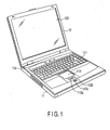
- FIG. 1 is a perspective view showing an external. configuration of an information processing apparatus according to an embodiment of the present invention.
- a notebook-type personal computer is shown here as an example.
- the notebook-type personal computer comprises a computer main body 11 and a display unit 12.
- a main display device 121 including an LCD is built into the display unit 12.
- the display unit 12 is attached to the computer main body 11 rotatably between an open position and a closed position.
- the computer main body 11 has a thin box-shaped case, and on an upper surface of the case, a power button 114 for turning on/off a power supply of the computer main body 11, a keyboard 111 and the like are disposed.
- An armrest is formed on the upper surface of the case portion before the keyboard 111. In an almost central portion of the armrest, a sub display device (touch pad device) 112 having a touch screen function is provided.
- the sub display device 112 forms a display-integrated type pointing device which is integrally provided with a display panel, such as the LCD having a display screen size smaller than that of the main display device 121, and a tablet, and this sub display device 112 is disposed on the upper surface of the case forming the armrest, together with a left button 113a, a right button 113b and a middle button 113c.
- the tablet is made of a transparent material, and the display panel is provided at the back of the tablet.
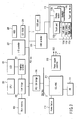
- FIG. 2 is a block diagram showing a system configuration of the computer shown in FIG. 1.
- the present system comprises a CPU 201, a host bridge 202, a main memory 203, a graphics controller 204, a PCI-ISA bridge 206, an I/O controller 207, a hard disk drive (HDD) 208, a CD-ROM drive 209, a USB'controller 210, an embedded controller/keyboard controller IC (EC/KBC) 211, a power supply controller 213 and the like.
- the sub display device 112 mentioned above is connected to the USE controller 210.
- the sub display device 112 integrates a touch pad 112a, a display section 112b and a backlight 112c to enable a touch screen function, and includes the left button 113a, the right button 113b and the middle button 113c.
- the CPU 201 controls an operation of the present embodiment, and executes an operating system (OS) loaded into the main memory 203 from the hard disk drive (HDD) 208, application programs, utility programs and the like.
- OS operating system
- HDD hard disk drive
- the CPU 201 executes processing of a control program (see FIG. 3) for the sub display device 112 and processing of an input-output program to enable a positioning processing function of a mouse pointer through one-touch operation on the sub display device 112 shown in FIG. 5 described later in collaboration with a mouse driver.
- the host bridge 202 is a bride device which bi-directionally connects a local bus of the CPU 201 and a PCI bus 1.
- the graphics controller 204 comprises a video RAM (VRAM), and controls the main display device 121 used as a display monitor of the present embodiment under the control of a dedicated display driver.
- the I/O controller 207 controls the hard disk drive (HDD) 208, the CD-ROM drive 209 and the like.
- the PCI-ISA bridge 206 is a bridge device which bi-directionally connects the PCI bus 1 and an ISA bus 2, and various kinds of system devices such as a system timer, a DMA controller and an interrupt controller are built therein.
- the embedded controller/keyboard controller IC (EC/KBC) 211 is a one-chip microcomputer in which an embedded controller (EC) for power management and a keyboard controller (KBC) for controlling the keyboard 111 are integrated.
- the embedded controller/keyboard controller IC (EC/KBC) 211 has a function to power on/off the present embodiment in accordance with an operation of the power button 114 by a user in collaboration with the power supply controller 213.
- FIG. 3 is a diagram showing functional components of the sub display device 112 in the embodiment of the present invention, and the components here include a setting table 301 which sets a function of the sub display device 112; a control program 302 which controls the function of the sub display device 112 in accordance with contents of the setting table 301; an interface 303 which controls input and output of information exchanged between the sub display device 112 and the control program 302; a setting program 311 which creates the setting table 301 by use of a GUI; execution means 312 for executing various kinds of processing in accordance with instructions from the control program 302; and the sub display device 112.
- a setting table 301 which sets a function of the sub display device 112
- a control program 302 which controls the function of the sub display device 112 in accordance with contents of the setting table 301
- an interface 303 which controls input and output of information exchanged between the sub display device 112 and the control program 302
- a setting program 311 which creates the setting table 301 by use of
- the execution means 312 switches the function of the sub display device 112 between a pointing function following the control of the mouse setting program, that is, a pointing operation input mode (default mode) which enables the mouse pointer on the main display device 121 to move by sliding a finger on the sub display device 112, and a mouse pointer positioning function (mouse pointer touch operation input mode) through one-touch operation on a virtual screen (see FIG. 5).
- a pointing operation input mode default mode
- mouse pointer positioning function mouse pointer touch operation input mode
- FIG. 4 is a view showing a relationship between a virtual screen 401 dealt with by the computer main body 11 and an actual display screen 402 of the main display device 121 in the embodiment described above. It is to be noted that, in this embodiment, a desktop entire screen to be displayed on the main display device 121 is referred to as the virtual screen 401, and the actual display screen 402 presently displayed on the main display device 121 is-referred to as a main operation screen.
- the display screen (main display) 121 including the LCD which is used as the display monitor of the present embodiment is incorporated into the display unit 12 provided at the computer main body 11.
- a screen image in a display area 402 allocated on a virtual screen 401 is displayed as the main operation screen on the main display device 121.
- a size (resolution) of the display area 402 is the same as a size (resolution) of a display screen (actual display screen) of the main display device 121.
- the screen image in the display area 402 is the screen image on the actual display screen of the main display device 121.
- a position of the display area 402 can be set in an optional position within the virtual screen 401 by a panning operation, as indicated by a broken line of FIG. 4.
- panning processing is performed under the control of the input-output program when a movement end (positioning end) of the mouse pointer is out of a display position of the main operation screen displayed on the main display device 121.
- the panning processing is performed to quickly move the display position of the main operation screen on the basis of relative positions of the virtual screen and the movement end of the mouse pointer in such a manner that relative positions of the main operation screen and the mouse pointer before the mouse pointer has been moved is maintained. This makes it easy to recognize the position of the mouse pointer on the main operation screen even when the display position of the main operation screen is switched (panned) and enables the positioning operation of the mouse pointer to be performed more easily and quickly.
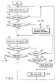
- FIG. 5 is a flowchart showing an operation processing procedure according to the embodiment of the present invention, which is achieved'by a cooperative processing of the control program 302 of the sub display device 112, the mouse driver and an input-output control program.
- This processing enables the mouse pointer positioning function by one-touch operation on the virtual screen using the sub display device 112.
- the middle button 113c is operated so as to switch the sub display device 112 to the mouse pointer touch operation input mode which enables the mouse pointer positioning function through one-touch operation on the virtual screen using the sub display device 112.
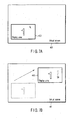
- FIGS. 6A and 6B and FIGS. 7A and 7B are views for explaining the positioning operation of the mouse pointer in the embodiment of the present invention.
- FIGS. 6A and 6B show operation examples on the sub display device 112
- FIGS. 7A and 7B show a display transition of the main operation screen on the virtual screen in accordance with the operation of FIGS. 6A and 6B.
- the sub display device 112 When the sub display device 112 is in the ordinary pointing function following the mouse setting program, that is, the pointing operation input mode (default mode) which enables the mouse pointer on the main display device 121 to move by sliding a finger on the sub display device 112, if the middle button 113c is operated as shown in FIG. 6A, the sub display device 112 switches to the mouse pointer positioning function (mouse pointer touch operation input mode) through one-touch operation on the virtual screen, and as shown in FIG. 6B, an image of the virtual screen is displayed on the sub display device 112.
- the mouse pointer positioning function mouse pointer touch operation input mode
- the image of the virtual screen clearly indicating an area (area surrounding a numeric value 1) 65 of the main operation screen displayed on the main display device 121 before the movement (positioning) of the mouse pointer, and the position of a mouse pointer 66 in the area 65 is displayed on the sub display device 112.
- the movement end (positioning end) of the mouse pointer can be pointed by touching one certain point with a figure.
- a touch operation position pointed position for the movement end of the mouse pointer in this case is indicated by "TP" in FIGS. 6B, 7B.
- FIGS. 7A and 7B show an example of a display transition of the main display device 121 when a position in a virtual screen space outside the area 65 of the main operation screen displayed on the main display device 121 is pointed by the positioning operation (touch operation) of the mouse pointer shown in FIGS. 6A and 6B.
- a display position of the mouse pointer on the main operation screen displayed on the main display device 121 is set (determined) by the processing in which the display position of the main operation screen is set on the basis of the relative positions of the virtual screen and the movement end of the mouse pointer in such a manner that the relative position between the main operation screen and the mouse pointer before the mouse pointer has been moved is maintained.
- the sub display device 112 After startup of the system, the sub display device 112 is in the ordinary pointing function that follows the mouse setting program, that is, the pointing operation input mode which enables the mouse pointer on the main display device 121 to move by sliding a finger on the sub display device 112. In this case, the sub display device 112 functions as a mouse pointing operation screen as shown in FIG. 6A (step S101 of FIG. 5).
- an operation mode (function) of the sub display device 112 switches from the pointing operation input mode shown in FIG. 6A to the mouse pointer touch operation input mode which enables the mouse pointer positioning function through one-touch operation on the virtual screen (desktop entire screen) as shown in FIG. 6B (step S104 of FIG. 5).
- the image of the virtual screen clearly indicating the area (area surrounding the numeric value 1) 65 of the main operation screen displayed on the main display device 121 before the positioning of the mouse pointer, and the position of the mouse pointer 66 in the area 65 of main operation screen is displayed on the sub display device 112.
- step S107 In a state where the virtual screen (desktop entire screen) is displayed on the sub display device 112, when one certain point on this screen is'touched (No in step S105 of FIG. 5, Yes in step S107), if the touched position (TP) is currently in the area 65 (area surrounding the numeric value 1) of the main operation screen displayed on the sub display device 112 (Yes in step S108 of FIG. 5), no change in made in the display position of the main display device 121 (the panning processing is not performed), and the mouse pointer displayed on the main display device 121 is moved to the movement end (positioning end) in accordance with the finger touch operation position (TP) (step S110 of FIG. 5).
- the display position of the mouse pointer on the main operation screen displayed on the main display device 121 is determined by the processing in which the display position of the main operation screen is quickly moved on the basis of the relative positions of the virtual screen and the movement end of the mouse pointer in such a manner that the relative position between the main operation screen and the mouse pointer before the mouse pointer has been moved is maintained.
- FIGS. 7A and 7B show an example of a transition of the main operation screen in the virtual screen displayed on the main display device 121 in this case.
- the operation mode (function) of the sub display device 112 switches from the mouse pointer touch operation input mode which enables the mouse pointer positioning function through one-touch operation on the virtual screen to the ordinary pointing operation input mode mentioned above (returns to the default mode).
- the ordinary pointing operation input mode and the mouse pointer touch operation input mode are alternately selected.
- predetermined processing allocated to the button is executed. For example, if the button 113a or 113b other than the middle button 113c is operated in the above processing, processing for the function allocated to the operated button 113a or 113b is executed (step S111 of FIG. 4).
- the screen image of the entire desktop including the main operation screen displayed on the main display device 121 is displayed on the sub display device 112 as an operation screen to point the position of the mouse pointer by the touch operation, thereby making it possible to easily and quickly move (position) the mouse pointer in a wide range on the desktop in a state where position accuracy of the mouse pointer is high.
- the screen image of the entire desktop including the main operation screen displayed on the main display device 121 is displayed on the sub display device 112 as the operation screen to point the position of the mouse pointer by the touch operation, but the following configuration may also be adopted; the desktop screen image of the entire main operation screen displayed on the main display device 121 is displayed on the sub display device 112 as the operation screen to point the position of the mouse pointer by the touch operation, for example.
- This is effective in the positioning operation of the mouse pointer between places away from each other on the main operation screen, for example, between places in the vicinity of facing end points on the main operation screen displayed on the main display device 121.
- the operation mode (ordinary pointing operation input mode/mouse pointer touch operation input mode) of the sub display device 112 is switched by the operation of the middle button 113c in the embodiment described above, but the operation mode can also be automatically returned to the ordinary pointing operation input mode (returned to the default mode) after the positioning processing of the mouse pointer by the touch operation, for example.
- the display position of the main operation screen is set on the basis of the relative positions of the virtual screen and the movement end of the mouse pointer in such a manner that the relative position between the main operation screen and the mouse pointer before the mouse pointer has been moved is maintained, but the mouse pointer can also be displayed constantly at a predetermined position (e.g., center, corner) on the main operation screen, for example.
- a predetermined position e.g., center, corner
- an information processing apparatus and a method of operating a pointing device which realize a function operable to easily and quickly move and position a pointer in a wide range on a desktop in a state where position accuracy of the pointer is high.
- the present invention can be practiced as a computer readable recording medium in which a program for allowing the computer to function as predetermined means, allowing the computer to realize a predetermined function, or allowing the computer to conduct predetermined means.
Landscapes
- Engineering & Computer Science (AREA)
- Theoretical Computer Science (AREA)
- General Engineering & Computer Science (AREA)
- Physics & Mathematics (AREA)
- Computer Hardware Design (AREA)
- Human Computer Interaction (AREA)
- General Physics & Mathematics (AREA)
- Mathematical Physics (AREA)
- User Interface Of Digital Computer (AREA)
- Position Input By Displaying (AREA)
- Digital Computer Display Output (AREA)
- Controls And Circuits For Display Device (AREA)
Abstract
Description
Claims (16)
- An information processing apparatus characterized by comprising:a first display device (12) which displays a pointer; anda second display device (112) which displays a virtual screen including a screen of the first display device (12), characterized by further comprising:a display controller (201) which moves the pointer to a pointed position in the virtual screen of the second display device (112).
- The apparatus according to claim 1, characterized in that when the pointed position is out of the screen of the first display device (12), the display controller (201) changes a display position of the first display device (12) in the virtual screen.
- The apparatus according to claim 1, characterized in that after the pointer has been moved, the display controller (201) stops display of the virtual screen on the second display device (112).
- The apparatus according to claim 1, characterized in that
the second display device (112) has a switching function; and
the display controller (201) stops display of the virtual screen when the switching function is operated in a state where the virtual screen is displayed. - The apparatus according to claim 1, characterized in that when the pointed position is out of the screen of the first display device (12), the display controller (201) changes the screen of the first display device (12) in the virtual screen in accordance with relative positions of the virtual screen and the pointed position.
- The apparatus according to claim 1, characterized in that when the pointed position is out of the screen of the first display device (12), the display controller (201) changes the screen of the first display device (12) in the virtual screen in such a manner that relative positions of the displayed image of the first display device (12) and the pointer before the pointer has been moved is maintained.
- The apparatus according to claim 1, characterized in that when the pointed position is out of the screen of the first display device (12), the display controller (201) changes the screen of the first display device (12) in the virtual screen so that the pointer is displayed at a fixed position in the screen of the first display device (12).
- The apparatus according to claim 1, characterized in that the display controller (201) makes the second display device (112) display the virtual screen indicating the screen of the first display device (12) in the virtual screen and the position of the pointer.
- A method of operating pointing device, characterized by comprising:displaying a screen on which an operation based on a pointer is enabled on a first display device (12);displaying a virtual screen including the screen of the first display device (12) on a second display device (112); andmoving the pointer to a pointed position in the virtual screen of the second display device (112) based on a pointing operation on the virtual screen.
- The method according to claim 9, characterized by further comprising, when the pointed position is out of the screen of the first display device (12), changing a display position of the first display device (12) in the virtual screen.
- The method according to claim 9, characterized by further comprising, after the pointer has been moved, stopping display of the virtual screen on the second display device (112).
- The method according to claim 9, characterized in that
the second display device (112) has a switching function; and further comprising:stopping a display of the virtual screen when the switching function is operated in a state where the virtual screen is displayed. - The method according to claim 9, characterized by further comprising, when the pointed position is out of the screen of the first display device (12), changing the screen of the first display device (12) in the virtual screen in accordance with relative positions of the virtual screen and the pointed position.
- The method according to claim 9, characterized by further comprising, when the pointed position is out of the screen of the first display device (12), changing the screen of the first display device (12) in the virtual screen in such a manner that relative positions of the displayed image of the first display device (12) and the pointer before the pointer has been moved is maintained.
- The method according to claim 9, characterized by further comprising, when the pointed position is out of the screen of the first display device (12), changing the screen of the first display device (12) in the virtual screen so that the pointer is displayed at a fixed position in the screen of the first display device (12).
- The method according to claim 9, characterized by further comprising making the second display device (112) display the virtual screen indicating the screen of the first display device (12) in the virtual screen and the position of the pointer.
Applications Claiming Priority (2)
| Application Number | Priority Date | Filing Date | Title |
|---|---|---|---|
| JP2003024419A JP3811128B2 (en) | 2003-01-31 | 2003-01-31 | Information processing apparatus and pointer operating method |
| JP2003024419 | 2003-01-31 |
Publications (2)
| Publication Number | Publication Date |
|---|---|
| EP1450239A2 true EP1450239A2 (en) | 2004-08-25 |
| EP1450239A3 EP1450239A3 (en) | 2007-11-07 |
Family
ID=32732885
Family Applications (1)
| Application Number | Title | Priority Date | Filing Date |
|---|---|---|---|
| EP04002168A Withdrawn EP1450239A3 (en) | 2003-01-31 | 2004-01-30 | Information processing apparatus and method of operating pointing device |
Country Status (3)
| Country | Link |
|---|---|
| US (1) | US7292206B2 (en) |
| EP (1) | EP1450239A3 (en) |
| JP (1) | JP3811128B2 (en) |
Cited By (1)
| Publication number | Priority date | Publication date | Assignee | Title |
|---|---|---|---|---|
| EP1739498A3 (en) * | 2005-06-28 | 2007-09-05 | Konica Minolta Business Technologies, Inc. | Image forming apparatus including a display unit |
Families Citing this family (21)
| Publication number | Priority date | Publication date | Assignee | Title |
|---|---|---|---|---|
| JP2006146556A (en) * | 2004-11-19 | 2006-06-08 | Nintendo Co Ltd | Image display processing program and image display processing device |
| US8487910B2 (en) * | 2005-05-02 | 2013-07-16 | Smart Technologies Ulc | Large scale touch system and methods for interacting with same |
| JP2007158919A (en) * | 2005-12-07 | 2007-06-21 | Fujifilm Corp | Image display device and image display method |
| US20070165370A1 (en) * | 2006-01-13 | 2007-07-19 | Yao-Shih Leng | Portable computer with multiple monitors |
| EP1832965A1 (en) * | 2006-03-10 | 2007-09-12 | E-Lead Electronic Co., Ltd. | Composite cursor input method |
| US20100107116A1 (en) * | 2008-10-27 | 2010-04-29 | Nokia Corporation | Input on touch user interfaces |
| US20100107067A1 (en) * | 2008-10-27 | 2010-04-29 | Nokia Corporation | Input on touch based user interfaces |
| JP5540344B2 (en) | 2008-10-30 | 2014-07-02 | シャープ株式会社 | Electronic device, menu selection method, menu selection program |
| JP2010108448A (en) * | 2008-10-31 | 2010-05-13 | Sharp Corp | Data transmission support device, electronic equipment, and method of controlling the data transmission support device |
| JP5154368B2 (en) * | 2008-10-31 | 2013-02-27 | シャープ株式会社 | COMMUNICATION DEVICE AND ITS CONTROL METHOD |
| WO2010092993A1 (en) * | 2009-02-13 | 2010-08-19 | 株式会社 東芝 | Information processing device |
| CN102414649B (en) | 2009-04-30 | 2015-05-20 | 辛纳普蒂克斯公司 | Operating a touch screen control system according to a plurality of rule sets |
| TWI408671B (en) * | 2009-05-15 | 2013-09-11 | Wistron Corp | Portable electronic device |
| US20100295799A1 (en) | 2009-05-21 | 2010-11-25 | Sony Computer Entertainment America Inc. | Touch screen disambiguation based on prior ancillary touch input |
| WO2011037558A1 (en) | 2009-09-22 | 2011-03-31 | Apple Inc. | Device, method, and graphical user interface for manipulating user interface objects |
| US9310907B2 (en) | 2009-09-25 | 2016-04-12 | Apple Inc. | Device, method, and graphical user interface for manipulating user interface objects |
| US8832585B2 (en) | 2009-09-25 | 2014-09-09 | Apple Inc. | Device, method, and graphical user interface for manipulating workspace views |
| JP2011134278A (en) * | 2009-12-25 | 2011-07-07 | Toshiba Corp | Information processing apparatus and pointing control method |
| US8797283B2 (en) | 2010-11-22 | 2014-08-05 | Sony Computer Entertainment America Llc | Method and apparatus for performing user-defined macros |
| US8907903B2 (en) | 2011-01-13 | 2014-12-09 | Sony Computer Entertainment America Llc | Handing control of an object from one touch input to another touch input |
| KR20140134940A (en) * | 2013-05-15 | 2014-11-25 | 삼성전자주식회사 | Mobile terminal and method for controlling touch screen and system threefor |
Family Cites Families (11)
| Publication number | Priority date | Publication date | Assignee | Title |
|---|---|---|---|---|
| DE19543377A1 (en) * | 1995-11-21 | 1997-05-22 | Philips Patentverwaltung | Method and arrangement for displaying images from an image group |
| US5841435A (en) * | 1996-07-26 | 1998-11-24 | International Business Machines Corporation | Virtual windows desktop |
| US5923307A (en) * | 1997-01-27 | 1999-07-13 | Microsoft Corporation | Logical monitor configuration in a multiple monitor environment |
| JP2000339097A (en) | 1998-12-16 | 2000-12-08 | Sony Corp | Information processing apparatus, control method therefor, and recording medium |
| US6407779B1 (en) * | 1999-03-29 | 2002-06-18 | Zilog, Inc. | Method and apparatus for an intuitive universal remote control system |
| JP2000279399A (en) | 1999-03-31 | 2000-10-10 | Fuji Photo Film Co Ltd | Method and device for measuring radiation picture |
| KR100648231B1 (en) * | 1999-10-19 | 2006-11-24 | 삼성전자주식회사 | A portable computer comprising the pointing device using an auxiliary liquid crystal display panel having a touch screen and a method thereof |
| JP5039911B2 (en) * | 2000-10-11 | 2012-10-03 | インターナショナル・ビジネス・マシーンズ・コーポレーション | Data processing device, input / output device, touch panel control method, storage medium, and program transmission device |
| US7730401B2 (en) * | 2001-05-16 | 2010-06-01 | Synaptics Incorporated | Touch screen with user interface enhancement |
| US20050024341A1 (en) * | 2001-05-16 | 2005-02-03 | Synaptics, Inc. | Touch screen with user interface enhancement |
| JP2004127048A (en) * | 2002-10-04 | 2004-04-22 | Toshiba Corp | Information processing equipment |
-
2003
- 2003-01-31 JP JP2003024419A patent/JP3811128B2/en not_active Expired - Fee Related
-
2004
- 2004-01-30 US US10/767,267 patent/US7292206B2/en not_active Expired - Lifetime
- 2004-01-30 EP EP04002168A patent/EP1450239A3/en not_active Withdrawn
Cited By (2)
| Publication number | Priority date | Publication date | Assignee | Title |
|---|---|---|---|---|
| EP1739498A3 (en) * | 2005-06-28 | 2007-09-05 | Konica Minolta Business Technologies, Inc. | Image forming apparatus including a display unit |
| US7627822B2 (en) | 2005-06-28 | 2009-12-01 | Konica Minolta Business Technologies, Inc. | Image forming apparatus |
Also Published As
| Publication number | Publication date |
|---|---|
| US20040239621A1 (en) | 2004-12-02 |
| EP1450239A3 (en) | 2007-11-07 |
| JP3811128B2 (en) | 2006-08-16 |
| JP2004234504A (en) | 2004-08-19 |
| US7292206B2 (en) | 2007-11-06 |
Similar Documents
| Publication | Publication Date | Title |
|---|---|---|
| US7292206B2 (en) | Information processing apparatus and method of operating pointing device | |
| US20070126714A1 (en) | Information processing apparatus and touch pad control method | |
| US8723821B2 (en) | Electronic apparatus and input control method | |
| US10949085B2 (en) | Electronic device | |
| US9274611B2 (en) | Electronic apparatus, input control program, and input control method | |
| EP1016952B1 (en) | Personal computer system | |
| US20030210285A1 (en) | Information processing apparatus and method of controlling the same | |
| US20090160805A1 (en) | Information processing apparatus and display control method | |
| US20090109187A1 (en) | Information processing apparatus, launcher, activation control method and computer program product | |
| JP2011248411A (en) | Information processor and display method for virtual keyboard | |
| JP2004127048A (en) | Information processing equipment | |
| JP6162299B1 (en) | Information processing apparatus, input switching method, and program | |
| US20130050127A1 (en) | Electronic apparatus | |
| US20060143580A1 (en) | Method and system for quick screen switching in a multi-monitor environment | |
| JP2010157038A (en) | Electronic apparatus and input control method | |
| US20070200822A1 (en) | Information processing apparatus and light projection control method | |
| US20040100451A1 (en) | Electronic apparatus and operation mode switching method | |
| EP1443388A2 (en) | Information processing apparatus and method of displaying operation window | |
| US20050138575A1 (en) | Information processing apparatus with display | |
| EP1338949A2 (en) | Information processing apparatus | |
| WO1998043202A1 (en) | Button wheel pointing device for notebook pcs | |
| JP2018010512A (en) | Information processing apparatus, erroneous operation suppression method, and program | |
| US20060271878A1 (en) | Information processing apparatus capable of displaying a plurality of windows | |
| JP2002259001A (en) | Method and device for window operation | |
| JP2011248465A (en) | Information processing apparatus and display control method |
Legal Events
| Date | Code | Title | Description |
|---|---|---|---|
| PUAI | Public reference made under article 153(3) epc to a published international application that has entered the european phase |
Free format text: ORIGINAL CODE: 0009012 |
|
| 17P | Request for examination filed |
Effective date: 20040130 |
|
| AK | Designated contracting states |
Kind code of ref document: A2 Designated state(s): AT BE BG CH CY CZ DE DK EE ES FI FR GB GR HU IE IT LI LU MC NL PT RO SE SI SK TR |
|
| AX | Request for extension of the european patent |
Extension state: AL LT LV MK |
|
| PUAL | Search report despatched |
Free format text: ORIGINAL CODE: 0009013 |
|
| AK | Designated contracting states |
Kind code of ref document: A3 Designated state(s): AT BE BG CH CY CZ DE DK EE ES FI FR GB GR HU IE IT LI LU MC NL PT RO SE SI SK TR |
|
| AX | Request for extension of the european patent |
Extension state: AL LT LV MK |
|
| 17Q | First examination report despatched |
Effective date: 20080115 |
|
| AKX | Designation fees paid |
Designated state(s): DE FR GB |
|
| STAA | Information on the status of an ep patent application or granted ep patent |
Free format text: STATUS: THE APPLICATION IS DEEMED TO BE WITHDRAWN |
|
| 18D | Application deemed to be withdrawn |
Effective date: 20100714 |