EP1832965A1 - Composite cursor input method - Google Patents
Composite cursor input method Download PDFInfo
- Publication number
- EP1832965A1 EP1832965A1 EP06110984A EP06110984A EP1832965A1 EP 1832965 A1 EP1832965 A1 EP 1832965A1 EP 06110984 A EP06110984 A EP 06110984A EP 06110984 A EP06110984 A EP 06110984A EP 1832965 A1 EP1832965 A1 EP 1832965A1
- Authority
- EP
- European Patent Office
- Prior art keywords
- cursor
- displacement
- control pad
- screen
- point
- Prior art date
- Legal status (The legal status is an assumption and is not a legal conclusion. Google has not performed a legal analysis and makes no representation as to the accuracy of the status listed.)
- Withdrawn
Links
Images


Classifications
-
- G—PHYSICS
- G06—COMPUTING; CALCULATING OR COUNTING
- G06F—ELECTRIC DIGITAL DATA PROCESSING
- G06F3/00—Input arrangements for transferring data to be processed into a form capable of being handled by the computer; Output arrangements for transferring data from processing unit to output unit, e.g. interface arrangements
- G06F3/01—Input arrangements or combined input and output arrangements for interaction between user and computer
- G06F3/03—Arrangements for converting the position or the displacement of a member into a coded form
- G06F3/033—Pointing devices displaced or positioned by the user, e.g. mice, trackballs, pens or joysticks; Accessories therefor
- G06F3/038—Control and interface arrangements therefor, e.g. drivers or device-embedded control circuitry
-
- G—PHYSICS
- G06—COMPUTING; CALCULATING OR COUNTING
- G06F—ELECTRIC DIGITAL DATA PROCESSING
- G06F1/00—Details not covered by groups G06F3/00 - G06F13/00 and G06F21/00
- G06F1/16—Constructional details or arrangements
- G06F1/1613—Constructional details or arrangements for portable computers
- G06F1/1626—Constructional details or arrangements for portable computers with a single-body enclosure integrating a flat display, e.g. Personal Digital Assistants [PDAs]
-
- G—PHYSICS
- G06—COMPUTING; CALCULATING OR COUNTING
- G06F—ELECTRIC DIGITAL DATA PROCESSING
- G06F1/00—Details not covered by groups G06F3/00 - G06F13/00 and G06F21/00
- G06F1/16—Constructional details or arrangements
- G06F1/1613—Constructional details or arrangements for portable computers
- G06F1/1633—Constructional details or arrangements of portable computers not specific to the type of enclosures covered by groups G06F1/1615 - G06F1/1626
- G06F1/1684—Constructional details or arrangements related to integrated I/O peripherals not covered by groups G06F1/1635 - G06F1/1675
- G06F1/169—Constructional details or arrangements related to integrated I/O peripherals not covered by groups G06F1/1635 - G06F1/1675 the I/O peripheral being an integrated pointing device, e.g. trackball in the palm rest area, mini-joystick integrated between keyboard keys, touch pads or touch stripes
-
- G—PHYSICS
- G06—COMPUTING; CALCULATING OR COUNTING
- G06F—ELECTRIC DIGITAL DATA PROCESSING
- G06F3/00—Input arrangements for transferring data to be processed into a form capable of being handled by the computer; Output arrangements for transferring data from processing unit to output unit, e.g. interface arrangements
- G06F3/01—Input arrangements or combined input and output arrangements for interaction between user and computer
- G06F3/03—Arrangements for converting the position or the displacement of a member into a coded form
- G06F3/033—Pointing devices displaced or positioned by the user, e.g. mice, trackballs, pens or joysticks; Accessories therefor
- G06F3/0354—Pointing devices displaced or positioned by the user, e.g. mice, trackballs, pens or joysticks; Accessories therefor with detection of 2D relative movements between the device, or an operating part thereof, and a plane or surface, e.g. 2D mice, trackballs, pens or pucks
- G06F3/03547—Touch pads, in which fingers can move on a surface
-
- G—PHYSICS
- G06—COMPUTING; CALCULATING OR COUNTING
- G06F—ELECTRIC DIGITAL DATA PROCESSING
- G06F3/00—Input arrangements for transferring data to be processed into a form capable of being handled by the computer; Output arrangements for transferring data from processing unit to output unit, e.g. interface arrangements
- G06F3/01—Input arrangements or combined input and output arrangements for interaction between user and computer
- G06F3/048—Interaction techniques based on graphical user interfaces [GUI]
- G06F3/0487—Interaction techniques based on graphical user interfaces [GUI] using specific features provided by the input device, e.g. functions controlled by the rotation of a mouse with dual sensing arrangements, or of the nature of the input device, e.g. tap gestures based on pressure sensed by a digitiser
- G06F3/0488—Interaction techniques based on graphical user interfaces [GUI] using specific features provided by the input device, e.g. functions controlled by the rotation of a mouse with dual sensing arrangements, or of the nature of the input device, e.g. tap gestures based on pressure sensed by a digitiser using a touch-screen or digitiser, e.g. input of commands through traced gestures
Definitions
- the present invention relates to a composite cursor input method and particularly to a composite cursor input method that moves a cursor through at least two different ratios.
- the computer technology is increasing focusing on humanized concept. Operation mainly adopts window menu selection. By moving the cursor through a mouse, selecting operation can be done rapidly. On the notebook computers that demands small size, a Touch-sensitive pad usually is provided to replace the mouse to control the cursor to make fast movement.
- the notebook computer mostly uses the Touch-sensitive pad to replace the mouse to overcome the problems of bulky size and line connection occurred to the mouse, to facilitate operation and carrying the Touch-sensitive pad is made with a limited size.
- the coordinate resolution of the Touch-sensitive pad is amplified proportionally to the screen coordinates.
- a small movement of a finger on the Touch-sensitive pad can generate a greater displacement for the cursor on the screen.
- the cursor can be moved to any position on the screen.
- the coordinate resolution of the Touch-sensitive pad corresponding to the coordinates on the screen is too large, to move the cursor accurately to the required location is difficult.
- a composite cursor input method that has at least two cursor control pads to provide a composite and non-proportional input to control movement of a cursor on a screen.
- the method includes at least the following procedures: (1) get a cursor position on the screen, (2) get a displacement signal, (3) jointly calculate a displacement value, and (4) move the cursor on the screen. By means of this approach the cursor can be moved rapidly.
- the displacement signal set forth above includes at least a first displacement signal of finger movement detected on a first cursor control pad and a second displacement signal of finger movement detected on a second cursor control pad, and may also include a third displacement signal of finger movement detected on a third cursor control pad.
- the ratio of the coordinate resolution of the first displacement signal of the first cursor control pad against the coordinates of the screen is much greater than the ratio of the coordinate resolution of the second displacement signal of the second cursor control pad against the coordinates of the screen.
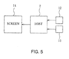
- the composite cursor input device 1 includes at least a first cursor control pad 12 and a second cursor control pad 13 that are installed on a surface 11 of a base 10 accessible by user's fingers to control movement of a cursor 141 on a screen 14.
- the first cursor control pad 12 and the second cursor control pad 13 have respectively a surface 120 and 130. They are Touch-sensitive pads that may be resistor induction panels or condenser induction panels to detect touching of fingers to generate displacement signals.
- the first and second cursor control panes 12 and 13 further have respectively a pressure switch 121 and 131 to detect the depressing pressure of the fingers to function as an input confirmation key.
- the surfaces 120 and 130 of the first and second cursor control pad 12 and 13 have respectively a mark G touchable by the fingers to recognize the touch position.
- the mark G may be an indented or a bulged spot, or a trace distinguishable by touching of the fingers.
- the first and second cursor control pad 12 and 13 are controlled by at least one button 15 to complete all functions of a mouse, or to switch to desired operation modes.
- the input method of the invention includes at least the following procedures (also referring to FIGS. 4 and 5)
- the step of calculate jointly a displacement value (step 33) set forth above can be done based on absolute coordinate values to get the displacement of the cursor 141.
- the finger moves on the first cursor control pad 12 from point d1 to d2, the coordinate of point d2 is (X1, Y1); and the finger moves on the second cursor control pad 13 from point c1 to c2, the coordinate is (X2, Y2); then the displacement value of the cursor calculated based on the absolute coordinate values is: A . X ⁇ 1 , Y ⁇ 1 + B . X ⁇ 2 , Y ⁇ 2 , where A and B are constants, and A is greater than B.
- the values of A and B are adjustable.
- the finger moves to a segment 12a where point d2 is located on the first cursor control pad 12 (referring to FIG. 6, the broken line is a pseudo line) that is directly corresponding to moving the corresponding cursor 141 to point e1 on a large segment 14a of the screen 14.
- the finger moves to a segment 13c where point c2 is located on the second cursor control pad 13 that is directly corresponding to moving the corresponding cursor 141 to point e2 on a small segment 14ac on the large segment 14a of the screen 14.
- the step of calculate jointly a displacement value (step 33) set forth above can also be done based on relative coordinate values to get the displacement of the cursor 141.
- the finger moves on the first cursor control pad 12 from point d1 to d2, the coordinate of point d1 is (X1', Y1'), and the coordinate of point d2 is (X1, Y1); and the finger moves on the second cursor control pad 13 from point c1 to c2, the coordinate of point c1 is (X2', Y2'), the coordinate of point c2 is (X2, Y2); then the displacement value of the cursor calculated based on the relative coordinate values is: A .
- the step of calculate jointly a displacement value (step 33) set forth above can also be done based on mixed calculation using the relative coordinate values and absolute coordinate values to get the displacement of the cursor 141.
- the displacement of the second cursor control pad 13 adopts the relative coordinate values.
- the finger moves from point d 1 to point d2 on the first cursor control pad 12, where the coordinate (X1, Y1) of point d2 is an absolute coordinate value; and the finger moves from point c1 to point c2 on the second cursor control pad 13, the coordinate of point c1 is (X2', Y2') and the coordinate of point c2 is (X2, Y2) are relative coordinate values; then the calculated displacement value of the cursor is: A .
- a and B are constants, and A is greater than B.
- the values of A and B are adjustable.
- step 33 For an embodiment that adopts joint calculation of a displacement value through the absolute coordinate value (step 33).
- a picture 140 of a document cannot be fully displayed on the screen 14 (namely the size of the displaying data is larger than the screen, and only a portion of data can be displayed)
- a condition frequently happens to browsing Web pages, or viewing the Web pages on a small screen such as PDAs or the like where the picture 140 of the entire document cannot be fully displayed
- either the first or second cursor control pad 12 or 13 can be set to the same area as the picture 140.
- the calculation based on the absolute coordinate value can be adopted.
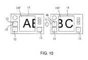
- the first displacement signal of moving the finger from point d3 (d4) on the first cursor control pad 12 displays a partial picture on the screen 14 corresponding to a partial segment 140' (140") to facilitate fast Web page browsing; or a third cursor control pad 15 (referring to FIGS. 8 and 10) can be added to accomplish the partial picture moving operation mentioned above.
- a third displacement signal of the finger moving to point d5 (d6) on the third cursor control pad 15 will display a corresponding picture of the partial segment 140' (140").
- FIG. 3 is a diagrammatic representation of FIG. 3
- FIG. 5 is a diagrammatic representation of FIG. 5
Abstract
Description
- The present invention relates to a composite cursor input method and particularly to a composite cursor input method that moves a cursor through at least two different ratios.
- The computer technology is increasing focusing on humanized concept. Operation mainly adopts window menu selection. By moving the cursor through a mouse, selecting operation can be done rapidly. On the notebook computers that demands small size, a Touch-sensitive pad usually is provided to replace the mouse to control the cursor to make fast movement.
- While the notebook computer mostly uses the Touch-sensitive pad to replace the mouse to overcome the problems of bulky size and line connection occurred to the mouse, to facilitate operation and carrying the Touch-sensitive pad is made with a limited size. Hence in the conventional design the coordinate resolution of the Touch-sensitive pad is amplified proportionally to the screen coordinates. Thus a small movement of a finger on the Touch-sensitive padcan generate a greater displacement for the cursor on the screen. Thereby the cursor can be moved to any position on the screen. However, if the coordinate resolution of the Touch-sensitive pad corresponding to the coordinates on the screen is too large, to move the cursor accurately to the required location is difficult. On the other hand, if the coordinate resolution of the Touch-sensitive pad corresponding to the coordinates on the screen is too small, moving the cursor accurately to the required location on the screen is easier, but the response of the cursor becomes insensitive. As a result, the finger has to move on the Touch-sensitive pad repeatedly to move the cursor, and use convenience drops.
- In view of the aforesaid problems, it is an object of the present invention to provide a composite cursor input method that has at least two cursor control pads to provide a composite and non-proportional input to control movement of a cursor on a screen. The method includes at least the following procedures: (1) get a cursor position on the screen, (2) get a displacement signal, (3) jointly calculate a displacement value, and (4) move the cursor on the screen. By means of this approach the cursor can be moved rapidly.
- The displacement signal set forth above includes at least a first displacement signal of finger movement detected on a first cursor control pad and a second displacement signal of finger movement detected on a second cursor control pad, and may also include a third displacement signal of finger movement detected on a third cursor control pad.
- The ratio of the coordinate resolution of the first displacement signal of the first cursor control pad against the coordinates of the screen is much greater than the ratio of the coordinate resolution of the second displacement signal of the second cursor control pad against the coordinates of the screen.
- The foregoing, as well as additional objects, features and advantages of the invention will be more readily apparent from the following detailed description, which proceeds with reference to the accompanying drawings.
-
- FIG. 1 is a perspective view of an embodiment of the input device of the invention.
- FIG. 2 is a perspective view of the first and second cursor control pads of the invention.
- FIG. 3 is a flow chart of the input method of the invention.
- FIG. 4 is a schematic view for controlling cursor movement in operation-1 according to the invention.
- FIG. 5 is an operation block diagram of the invention.
- FIG. 6 is a schematic view for controlling cursor movement in operation-2 according to the invention.
- FIG. 7 is a schematic view for controlling cursor movement in operation-3 according to the invention.
- FIG. 8 is a schematic view for controlling cursor movement in operation-4 according to the invention.
- FIG. 9 is a schematic view of an embodiment of a fragmentary picture of the invention.
- FIG. 10 is a schematic view of another embodiment of a fragmentary picture of the invention.
- Referring to FIG. 1, the composite
cursor input device 1 according to the invention includes at least a firstcursor control pad 12 and a secondcursor control pad 13 that are installed on asurface 11 of abase 10 accessible by user's fingers to control movement of acursor 141 on ascreen 14. - Referring to FIG. 2, the first
cursor control pad 12 and the secondcursor control pad 13 have respectively asurface cursor control panes pressure switch - The
surfaces cursor control pad - The first and second
cursor control pad button 15 to complete all functions of a mouse, or to switch to desired operation modes. - Refer to FIG. 3, the input method of the invention includes at least the following procedures (also referring to FIGS. 4 and 5)
- 1. Obtain a cursor position on a screen (step 31): a
host 2 gets a present position e0 of thecursor 141 on thescreen 14 that serves as the starting point; - 2. Obtain a displacement signal (step 32): the first and second
cursor control pads cursor control pad 12 while the finger moves from point d1 to point d2, and the second displacement signal generated by the secondcursor control pad 13 while the finger moves frompoint c 1 to point c2; - 3. Calculate jointly a displacement value (step 33): based on the first and second displacement signals to jointly calculate the displacement of the cursor;
- 4. Move the cursor on the screen (step 34): based on the calculated cursor displacement, move the
cursor 141 on thescreen 14 to a new corresponding position. For instance, thecursor 141 corresponding to the first displacement signal is moved from point e0 to e1, and thecursor 141 corresponding to the second displacement signal is moved from point e1 to e2. - The step of calculate jointly a displacement value (step 33) set forth above can be done based on absolute coordinate values to get the displacement of the
cursor 141. For instance, the finger moves on the firstcursor control pad 12 from point d1 to d2, the coordinate of point d2 is (X1, Y1); and the finger moves on the secondcursor control pad 13 from point c1 to c2, the coordinate is (X2, Y2); then the displacement value of the cursor calculated based on the absolute coordinate values is:
where A and B are constants, and A is greater than B. The values of A and B are adjustable. During operation, for moving thecursor 141 through the firstcursor control pad 12, the finger moves to asegment 12a where point d2 is located on the first cursor control pad 12 (referring to FIG. 6, the broken line is a pseudo line) that is directly corresponding to moving thecorresponding cursor 141 to point e1 on alarge segment 14a of thescreen 14. For moving thecursor 141 through the secondcursor control pad 13, the finger moves to asegment 13c where point c2 is located on the secondcursor control pad 13 that is directly corresponding to moving thecorresponding cursor 141 to point e2 on a small segment 14ac on thelarge segment 14a of thescreen 14. - The step of calculate jointly a displacement value (step 33) set forth above can also be done based on relative coordinate values to get the displacement of the
cursor 141. For instance, the finger moves on the firstcursor control pad 12 from point d1 to d2, the coordinate of point d1 is (X1', Y1'), and the coordinate of point d2 is (X1, Y1); and the finger moves on the secondcursor control pad 13 from point c1 to c2, the coordinate of point c1 is (X2', Y2'), the coordinate of point c2 is (X2, Y2); then the displacement value of the cursor calculated based on the relative coordinate values is:
where A and B are constants, and A is greater than B. The values of A and B are adjustable. For moving thecursor 141 through the first cursor control pad 12 (referring to FIG. 4), the finger moves an interval f1 from point d1 to point d2 on the firstcursor control pad 12 corresponding to moving thecursor 141 on thescreen 14 at a corresponding large interval F1 from point e0 to point e1, whereA. f 1=F 1 ; for moving thecursor 141 through the secondcursor control pad 13, the finger moves an interval f2 from point c1 to point c2 on the secondcursor control pad 13 corresponding moving thecursor 141 on thescreen 14 at a small interval F2 from point e1 to point e2, where B .f 2 = F2. - The step of calculate jointly a displacement value (step 33) set forth above can also be done based on mixed calculation using the relative coordinate values and absolute coordinate values to get the displacement of the
cursor 141. Namely the displacement of the secondcursor control pad 13 adopts the relative coordinate values. For instance the finger moves frompoint d 1 to point d2 on the firstcursor control pad 12, where the coordinate (X1, Y1) of point d2 is an absolute coordinate value; and the finger moves from point c1 to point c2 on the secondcursor control pad 13, the coordinate of point c1 is (X2', Y2') and the coordinate of point c2 is (X2, Y2) are relative coordinate values; then the calculated displacement value of the cursor is:
where A and B are constants, and A is greater than B. The values of A and B are adjustable. For moving the cursor through the first cursor control pad 12 (referring to FIG. 7), the finger moves to asegment 12a on the firstcursor control pad 12 where point d2 is located directly corresponding to moving thecursor 141 to point e1 on alarge segment 14a of thescreen 14; and the secondcursor control pad 13 controls moving of thecursor 141 by moving the finger from point c1 to point c2 at an interval f2 corresponding to moving thecursor 141 on thescreen 14 from point e1 to point e2 at a small interval F2, wherein B .f 2 = F2. - Refer to FIGS. 8 and 9 for an embodiment that adopts joint calculation of a displacement value through the absolute coordinate value (step 33). When a
picture 140 of a document cannot be fully displayed on the screen 14 (namely the size of the displaying data is larger than the screen, and only a portion of data can be displayed), such a condition frequently happens to browsing Web pages, or viewing the Web pages on a small screen such as PDAs or the like where thepicture 140 of the entire document cannot be fully displayed, either the first or secondcursor control pad picture 140. And the calculation based on the absolute coordinate value can be adopted. Thereby on either the first or secondcursor control pad 12 or 13 (the first cursor control pad is selected as an example), the first displacement signal of moving the finger from point d3 (d4) on the firstcursor control pad 12 displays a partial picture on thescreen 14 corresponding to a partial segment 140' (140") to facilitate fast Web page browsing; or a third cursor control pad 15 (referring to FIGS. 8 and 10) can be added to accomplish the partial picture moving operation mentioned above. Namely a third displacement signal of the finger moving to point d5 (d6) on the thirdcursor control pad 15 will display a corresponding picture of the partial segment 140' (140"). -
- 31 - Get a cursor position on a screen
- 32 - Get a displacement signal
- 33 - Calculate jointly a displacement value
- 34 - Move the cursor on the screen
-
- 2 - Host, 14 - Screen
Claims (7)
- A composite cursor input method, comprising at least the following steps:1-1. getting a cursor position on a screen;1-2. getting a displacement signal;1-3. calculating jointly a displacement value; and1-4. moving the cursor on the screen.
- The method of claim 1, wherein the calculating jointly a displacement value is based on displacement signals of a first cursor control pad and a second cursor control pad, the displacement signals including a first displacement signal of a finger movement detected by the first cursor control pad and a second displacement signal of another finger movement detected by the second cursor control pad.
- The method of claim 1, wherein the displacement signals further includes a third displacement signal of yet another finger movement detected by a third cursor control pad.
- The method of claim 2, wherein the calculating jointly a displacement value is based on the first displacement signal and the second displacement value through a joint calculation according to absolute coordinate values to get the displacement value of the cursor.
- The method of claim 2, wherein the calculating jointly a displacement value is based on the first displacement signal and the second displacement signal through a joint calculation according to relative coordinate values to get the displacement value of the cursor.
- The method of claim 2, wherein the calculating jointly a displacement value is based on the first displacement signal adopting an absolute coordinate value and the second displacement signal adopting a relative coordinate value to perform a mixed calculation to get the displacement value of the cursor.
- The method of claim 2, wherein when the screen is smaller than displaying data and can only display a portion of the data, at least one of the first and the second displacement signals moves the portion where the data is displayed.
Priority Applications (1)
| Application Number | Priority Date | Filing Date | Title |
|---|---|---|---|
| EP06110984A EP1832965A1 (en) | 2006-03-10 | 2006-03-10 | Composite cursor input method |
Applications Claiming Priority (1)
| Application Number | Priority Date | Filing Date | Title |
|---|---|---|---|
| EP06110984A EP1832965A1 (en) | 2006-03-10 | 2006-03-10 | Composite cursor input method |
Publications (1)
| Publication Number | Publication Date |
|---|---|
| EP1832965A1 true EP1832965A1 (en) | 2007-09-12 |
Family
ID=36577557
Family Applications (1)
| Application Number | Title | Priority Date | Filing Date |
|---|---|---|---|
| EP06110984A Withdrawn EP1832965A1 (en) | 2006-03-10 | 2006-03-10 | Composite cursor input method |
Country Status (1)
| Country | Link |
|---|---|
| EP (1) | EP1832965A1 (en) |
Citations (11)
| Publication number | Priority date | Publication date | Assignee | Title |
|---|---|---|---|---|
| JPH05298025A (en) * | 1992-04-16 | 1993-11-12 | Canon Inc | Information processor |
| JPH09258901A (en) * | 1996-03-26 | 1997-10-03 | Smk Corp | Coordinate input device and cursor control system by the same |
| JPH10187338A (en) * | 1996-12-20 | 1998-07-14 | Mitsumi Electric Co Ltd | Point pad |
| EP0992878A2 (en) * | 1998-10-01 | 2000-04-12 | Hewlett-Packard Company | Apparatus and method for achieving absolute and relative positioning of a graphics cursor |
| EP1016952A1 (en) * | 1998-12-28 | 2000-07-05 | Alps Electric Co., Ltd. | Personal computer system |
| US20030025678A1 (en) * | 2001-08-04 | 2003-02-06 | Samsung Electronics Co., Ltd. | Apparatus with touch screen and method for displaying information through external display device connected thereto |
| JP2003067128A (en) * | 2001-08-30 | 2003-03-07 | Sharp Corp | Information processor with pad type pointing device |
| EP1302841A2 (en) * | 2001-10-10 | 2003-04-16 | Wacom Co., Ltd | Input system |
| JP2004086735A (en) * | 2002-08-28 | 2004-03-18 | Toshiba Corp | Electronic device and operating mode switching method |
| JP2004234504A (en) * | 2003-01-31 | 2004-08-19 | Toshiba Corp | Information processor and method for operating pointer |
| US20040263484A1 (en) * | 2003-06-25 | 2004-12-30 | Tapio Mantysalo | Multifunctional UI input device for moblie terminals |
-
2006
- 2006-03-10 EP EP06110984A patent/EP1832965A1/en not_active Withdrawn
Patent Citations (11)
| Publication number | Priority date | Publication date | Assignee | Title |
|---|---|---|---|---|
| JPH05298025A (en) * | 1992-04-16 | 1993-11-12 | Canon Inc | Information processor |
| JPH09258901A (en) * | 1996-03-26 | 1997-10-03 | Smk Corp | Coordinate input device and cursor control system by the same |
| JPH10187338A (en) * | 1996-12-20 | 1998-07-14 | Mitsumi Electric Co Ltd | Point pad |
| EP0992878A2 (en) * | 1998-10-01 | 2000-04-12 | Hewlett-Packard Company | Apparatus and method for achieving absolute and relative positioning of a graphics cursor |
| EP1016952A1 (en) * | 1998-12-28 | 2000-07-05 | Alps Electric Co., Ltd. | Personal computer system |
| US20030025678A1 (en) * | 2001-08-04 | 2003-02-06 | Samsung Electronics Co., Ltd. | Apparatus with touch screen and method for displaying information through external display device connected thereto |
| JP2003067128A (en) * | 2001-08-30 | 2003-03-07 | Sharp Corp | Information processor with pad type pointing device |
| EP1302841A2 (en) * | 2001-10-10 | 2003-04-16 | Wacom Co., Ltd | Input system |
| JP2004086735A (en) * | 2002-08-28 | 2004-03-18 | Toshiba Corp | Electronic device and operating mode switching method |
| JP2004234504A (en) * | 2003-01-31 | 2004-08-19 | Toshiba Corp | Information processor and method for operating pointer |
| US20040263484A1 (en) * | 2003-06-25 | 2004-12-30 | Tapio Mantysalo | Multifunctional UI input device for moblie terminals |
Non-Patent Citations (5)
| Title |
|---|
| PATENT ABSTRACTS OF JAPAN vol. 018, no. 100 (P - 1695) 17 February 1994 (1994-02-17) * |
| PATENT ABSTRACTS OF JAPAN vol. 1998, no. 02 30 January 1998 (1998-01-30) * |
| PATENT ABSTRACTS OF JAPAN vol. 1998, no. 12 31 October 1998 (1998-10-31) * |
| PATENT ABSTRACTS OF JAPAN vol. 2003, no. 07 3 July 2003 (2003-07-03) * |
| PATENT ABSTRACTS OF JAPAN vol. 2003, no. 12 5 December 2003 (2003-12-05) * |
Similar Documents
| Publication | Publication Date | Title |
|---|---|---|
| EP1674976B1 (en) | Improving touch screen accuracy | |
| KR101424294B1 (en) | Multi-touch uses, gestures, and implementation | |
| US8941600B2 (en) | Apparatus for providing touch feedback for user input to a touch sensitive surface | |
| US8370772B2 (en) | Touchpad controlling method and touch device using such method | |
| KR101242228B1 (en) | A user interface | |
| KR101453628B1 (en) | A user interface | |
| US9389722B2 (en) | User interface device that zooms image in response to operation that presses screen, image zoom method, and program | |
| EP1191430A1 (en) | Graphical user interface for devices having small tactile displays | |
| WO2013018480A1 (en) | User interface device comprising touch pad for shrinking and displaying source image within screen capable of touch input, input processing method and program | |
| CA2637513C (en) | Gesturing with a multipoint sensing device | |
| EP2225628B1 (en) | Method and system for moving a cursor and selecting objects on a touchscreen using a finger pointer | |
| EP0992878B1 (en) | Apparatus and method for achieving absolute and relative positioning of a graphics cursor | |
| US20070152959A1 (en) | Pressure-sensitive button | |
| US10599317B2 (en) | Information processing apparatus | |
| US9213482B2 (en) | Touch control device and method | |
| WO1998000775A9 (en) | Touchpad with scroll and pan regions | |
| EP2184671B1 (en) | Method and apparatus for switching touch screen of handheld electronic apparatus | |
| WO2007121676A1 (en) | Method and device for controlling information display output and input device | |
| CN101308428B (en) | Device, method, and computer readable medium for mapping a graphics tablet to an associated display | |
| JP5003377B2 (en) | Mark alignment method for electronic devices | |
| KR101447886B1 (en) | Method and apparatus for selecting contents through a touch-screen display | |
| US20070216656A1 (en) | Composite cursor input method | |
| JP2011081447A (en) | Information processing method and information processor | |
| JP5256755B2 (en) | Information processing method and information processing apparatus | |
| KR20140067861A (en) | Method and apparatus for sliding objects across touch-screen display |
Legal Events
| Date | Code | Title | Description |
|---|---|---|---|
| PUAI | Public reference made under article 153(3) epc to a published international application that has entered the european phase |
Free format text: ORIGINAL CODE: 0009012 |
|
| AK | Designated contracting states |
Kind code of ref document: A1 Designated state(s): AT BE BG CH CY CZ DE DK EE ES FI FR GB GR HU IE IS IT LI LT LU LV MC NL PL PT RO SE SI SK TR |
|
| AX | Request for extension of the european patent |
Extension state: AL BA HR MK YU |
|
| 17P | Request for examination filed |
Effective date: 20080219 |
|
| 17Q | First examination report despatched |
Effective date: 20080410 |
|
| AKX | Designation fees paid |
Designated state(s): AT BE BG CH CY CZ DE DK EE ES FI FR GB GR HU IE IS IT LI LT LU LV MC NL PL PT RO SE SI SK TR |
|
| STAA | Information on the status of an ep patent application or granted ep patent |
Free format text: STATUS: THE APPLICATION IS DEEMED TO BE WITHDRAWN |
|
| 18D | Application deemed to be withdrawn |
Effective date: 20080821 |