EP1450109B1 - Kombinierte Solarheizungsanlage mit Überhitzungsverwaltung und Verfahren zur Regulierung der Anlage. - Google Patents
Kombinierte Solarheizungsanlage mit Überhitzungsverwaltung und Verfahren zur Regulierung der Anlage. Download PDFInfo
- Publication number
- EP1450109B1 EP1450109B1 EP04354006A EP04354006A EP1450109B1 EP 1450109 B1 EP1450109 B1 EP 1450109B1 EP 04354006 A EP04354006 A EP 04354006A EP 04354006 A EP04354006 A EP 04354006A EP 1450109 B1 EP1450109 B1 EP 1450109B1
- Authority
- EP
- European Patent Office
- Prior art keywords
- storage
- fluid
- circulator
- recipient
- temperature
- Prior art date
- Legal status (The legal status is an assumption and is not a legal conclusion. Google has not performed a legal analysis and makes no representation as to the accuracy of the status listed.)
- Expired - Lifetime
Links
Images


Classifications
-
- F—MECHANICAL ENGINEERING; LIGHTING; HEATING; WEAPONS; BLASTING
- F24—HEATING; RANGES; VENTILATING
- F24D—DOMESTIC- OR SPACE-HEATING SYSTEMS, e.g. CENTRAL HEATING SYSTEMS; DOMESTIC HOT-WATER SUPPLY SYSTEMS; ELEMENTS OR COMPONENTS THEREFOR
- F24D19/00—Details
- F24D19/10—Arrangement or mounting of control or safety devices
- F24D19/1006—Arrangement or mounting of control or safety devices for water heating systems
- F24D19/1066—Arrangement or mounting of control or safety devices for water heating systems for the combination of central heating and domestic hot water
- F24D19/1075—Arrangement or mounting of control or safety devices for water heating systems for the combination of central heating and domestic hot water the system uses solar energy
-
- F—MECHANICAL ENGINEERING; LIGHTING; HEATING; WEAPONS; BLASTING
- F24—HEATING; RANGES; VENTILATING
- F24D—DOMESTIC- OR SPACE-HEATING SYSTEMS, e.g. CENTRAL HEATING SYSTEMS; DOMESTIC HOT-WATER SUPPLY SYSTEMS; ELEMENTS OR COMPONENTS THEREFOR
- F24D11/00—Central heating systems using heat accumulated in storage masses
- F24D11/002—Central heating systems using heat accumulated in storage masses water heating system
- F24D11/003—Central heating systems using heat accumulated in storage masses water heating system combined with solar energy
-
- Y—GENERAL TAGGING OF NEW TECHNOLOGICAL DEVELOPMENTS; GENERAL TAGGING OF CROSS-SECTIONAL TECHNOLOGIES SPANNING OVER SEVERAL SECTIONS OF THE IPC; TECHNICAL SUBJECTS COVERED BY FORMER USPC CROSS-REFERENCE ART COLLECTIONS [XRACs] AND DIGESTS
- Y02—TECHNOLOGIES OR APPLICATIONS FOR MITIGATION OR ADAPTATION AGAINST CLIMATE CHANGE
- Y02B—CLIMATE CHANGE MITIGATION TECHNOLOGIES RELATED TO BUILDINGS, e.g. HOUSING, HOUSE APPLIANCES OR RELATED END-USER APPLICATIONS
- Y02B10/00—Integration of renewable energy sources in buildings
- Y02B10/20—Solar thermal
-
- Y—GENERAL TAGGING OF NEW TECHNOLOGICAL DEVELOPMENTS; GENERAL TAGGING OF CROSS-SECTIONAL TECHNOLOGIES SPANNING OVER SEVERAL SECTIONS OF THE IPC; TECHNICAL SUBJECTS COVERED BY FORMER USPC CROSS-REFERENCE ART COLLECTIONS [XRACs] AND DIGESTS
- Y02—TECHNOLOGIES OR APPLICATIONS FOR MITIGATION OR ADAPTATION AGAINST CLIMATE CHANGE
- Y02B—CLIMATE CHANGE MITIGATION TECHNOLOGIES RELATED TO BUILDINGS, e.g. HOUSING, HOUSE APPLIANCES OR RELATED END-USER APPLICATIONS
- Y02B10/00—Integration of renewable energy sources in buildings
- Y02B10/70—Hybrid systems, e.g. uninterruptible or back-up power supplies integrating renewable energies
Definitions
- the invention relates to a combined solar installation comprising at least one solar collector, a storage container for an energy storage fluid, a circuit for circulating a fluid in the solar collectors, provided with a first circulator and intended to to allow the heating of the storage fluid by the solar collectors, and means for controlling the flow of fluid in the solar collectors.
- some facilities include a discharge loop.
- a discharge loop manually controlled by the user when the outside temperature is above a predetermined threshold, makes it possible to evacuate the excess energy in a mini floor heating connected in parallel to the heating elements, floor heating and / or radiators, of the installation and disposed in the ground, inside or outside the house to be heated.
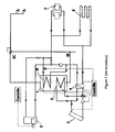
- the storage container 1 always containing sanitary water.
- the same fluid, containing antifreeze can circulate in the solar collectors 2, in the auxiliary heating 5, in the heating floor 6 and / or the heating radiators and in two heat exchangers 3 and 8 arranged in the storage container.
- the storage container 1 generally large (1000 to 15001), contains the heating fluid flowing in the auxiliary heating 5, the heating floor 6 and / or the heating radiators 7.
- the auxiliary heating 5 can be integrated in the storage container 1, as shown in FIG. 3, or disposed outside, as represented in FIG. 4.
- a fluid containing an antifreeze circulates in an independent circuit comprising the solar collectors 6 and a heat exchanger 3 disposed in the storage container 1.
- the domestic water circulates in at least a fourth heat exchanger 9 disposed in the storage container 1, or, as shown in FIG. 4, in the secondary circuit of a fifth heat exchanger 10, disposed at the outside of the heating container and having a primary circuit in which heating water circulates from the storage container 1.
- Document US-A-2002/112435 also describes a heating and cooling installation.
- An exchange of energy is ensured, at a storage tank, between an air circulation loop, passing through solar panels, and a water circulation loop of a heat pump that can be powered at from the tank.
- the system can operate in either heating mode or cooling mode. In the latter case, the air cooled during the night, when it passes through the solar panels, cools the fluid in the tank.
- the invention aims to overcome the disadvantages of known installations and, more particularly, automatically manage overheating that may occur, especially in summer.
- the installation comprises at least one temperature sensor disposed in the storage container, the control means comprising start-up means the first circulator during a night cooling phase, if the temperature of the storage fluid in the storage vessel exceeds a predetermined limit at a predetermined time of night, so as to cool the storage fluid contained in the storage vessel.
- the invention also relates to a method for controlling a combined solar installation, in which the control circuit controls, during a night-cooling phase, the circulation of fluid in the solar collectors, so as to cool the storage fluid contained in the storage container, when the temperature of the storage fluid in the container is above a predetermined limit temperature at a predetermined time of the night.
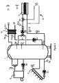
- the installation shown in FIG. 5 comprises, like the known installations, a storage container 1, at least one solar collector 2, a boiler constituting an auxiliary heating 5, a heating floor 6 and a heat exchanger 10, disposed at outside of the storage container.
- the sanitary water circulates in the secondary circuit of the heat exchanger 10, the cold water (EF) entering the heat exchanger 10 being heated to supply domestic hot water (EC).
- a second heating circuit comprising a second heating floor and / or heating radiators, may optionally be connected to the heating vessel 1.
- the input of the primary circuit of the heat exchanger 10 is connected to the upper end of the storage container 1, while the output of the circuit
- the primary heat exchanger 10 returns the cooled storage fluid to the lower end of the storage vessel.
- the auxiliary heater 5 is connected to the upper part of the storage container 1, so as to be supplied with storage fluid from an area just above the central portion of the storage container and to provide the storage fluid. heated storage at the top end of the storage container.
- the solar collectors 2 are connected to the lower part of the storage vessel, so as to be supplied with storage fluid from an area near the lower end of the storage vessel and to supply the heated storage fluid to the lower end of the storage container.
- the floor heater 6 is supplied with storage fluid from an area just above the central portion of the storage vessel and return the cooled storage fluid to the lower end of the storage vessel.
- the installation shown in FIG. 5 is almost monofluid, the storage fluid, or heat transfer fluid, circulating in all the components of the installation with the exception of the secondary circuit of the heat exchanger 10, in which the sanitary water.
- the energy is stored partly in the storage container 1 and, in part, in the heating floor 6.
- the storage container may be constituted by a balloon of approximately 400 l
- the capacity fluid storage of the floor heating can be of the order of 200I.
- the dimensioning of the installation takes into account the capacity of heat storage by a floor heating in concrete. For example, a floor of 150 m 2 and 10 cm thick, corresponding to a volume of 15 m 3 , has an energy storage capacity equivalent to that of 7 m 3 of water.
- the capacity of the storage container 1 must nevertheless be greater, for example of the order of 1000I, if the installation also comprises heating radiators.
- the storage fluid preferably comprises an antifreeze.
- the storage fluid may be constituted by a mixture, sufficiently liquid to circulate without difficulty inside the installation, comprising about 57% water and 43% antifreeze.
- the antifreeze content can generally be reduced to about 20% for protection down to -7 ° C.
- the antifreeze can be completely removed if the installation is intended to be used in a zone that does not fear frost.
- a control circuit 11 preferably microprocessor circuit, shown schematically in Figure 6, controls the actuation of circulators, for example constituted by pumps, arranged at different locations of the installation, taking into account the temperatures provided by sensors temperature and / or pressure disposed at predetermined locations of the installation.
- the installation also comprises a discharge loop 12 connected in parallel to the heating floor 6, via a zone valve V2 disposed upstream of the heating floor 6, downstream of the circulator S3.
- the discharge loop 12 is preferably constituted by one or two circuits, crosslinked polyethylene or equivalent material disposed in the soil outside or inside the house to be heated.
- the control circuit 11 is connected to the temperature sensors T1 to T13 and pressure P1, so as to receive signals representative of the temperatures ⁇ 1 to ⁇ 13, respectively measured by the temperature sensors T1 to T13, as well as signals representative of the pressure p1 measured by the pressure sensor P1 and flow rate signals D provided by a proportional flow detector (not shown) disposed in the cold water inlet (EF) upstream of the secondary circuit of the heat exchanger; 10.
- the control circuit supplies signals A1 to A4 for controlling circulators S1 to S4 and control signals B1 and B2 for valves V1 and V2. It also comprises programming means, shown schematically in Figure 6 by a programming input E allowing, for example, remotely program different threshold values, limit and setpoint and set the date and time.
- the plant shown in Figure 5 operates preferably as described below.
- the speed of the circulator S1 is automatically controlled by the control signals A1 supplied by the control circuit 11, so as to maintain a substantially constant difference (for example 2 ° C) between the temperatures ⁇ 3 and ⁇ 4, respectively measured by the temperature sensors T3 and T4.
- a substantially constant difference for example 2 ° C
- the speed of the circulator S1 is reduced and the amount of energy transferred to the storage container is adapted accordingly.
- the circulator S1 is stopped as soon as the temperature ⁇ 8 measured by the temperature sensor T8 exceeds a predetermined setpoint value T8cons, typically between 70 ° C. and 80 ° C., until that the temperature ⁇ 3 reaches a limit value T3lim, typically between 130 ° C and 140 ° C, and / or that the pressure p1 measured by the pressure sensor P1 reaches a limit value P1lim, typically of the order of 3 bars.
- a predetermined setpoint value T8cons typically between 70 ° C. and 80 ° C.
- the circulator S1 is put back into service, at a reduced speed, of the order of 10% of its nominal speed, until the measured values fall back respectively to below T3lim- ⁇ T3lim or P1lim- ⁇ P1lim. It is thus possible to limit the excessive temperatures in the storage container 1, by limiting, by controlling the flow rate of the circulator S1, the amount of energy injected into the storage container by the solar collectors 2.
- the limitation of the speed of the circulator S1 when the temperature ⁇ 8 of the storage fluid exceeds the set value T8cons makes it possible to operate the solar collectors 2 at an elevated temperature, close to T3lim, which reduces their efficiency and automatically limits the amount of energy injected in the storage container 1 by the solar collectors.
- the circulator S1 is restarted, for a running cycle of predetermined duration, when the limit temperature T3lim is reached. It is thus alternately subjected to a cycle of duration predetermined, at nominal speed, when the limit T3lim is reached, then at a stop cycle until this limit is reached again.
- the circulator S1 is turned on by the control circuit 11 if, at a predetermined time of the night, for example at 23h, the temperature ⁇ 8 of the storage fluid exceeds a predetermined value, which can be the setpoint T8cons (70 ° C to 80 ° C). The circulator S1 is then stopped when the temperature ⁇ 8 of the storage fluid has fallen below a predetermined threshold, which may be the setpoint value T8cons or a value lower than this, for example 60 ° C.
- the solar collectors 2 being connected to the lower part of the storage container 1, they essentially cool the bottom of the storage container during the night cooling phase.
- the control circuit causes a stirring of the storage fluid through a storage fluid circulation circuit communicating respectively with the upper and lower portions of the storage container.
- a storage fluid circulation circuit communicating respectively with the upper and lower portions of the storage container.
- the control circuit 11 then periodically controls, during the night cooling phase, the implementation of running of the circulator S4.
- FIG. 7 illustrates an exemplary embodiment of a flowchart that can be used by the microprocessor of the control circuit 11 to automatically manage overheating.
- step F8 stirring storage fluid
- FIG. 8 A particular embodiment of the stirring step, in which the stirring is carried out by a periodical start-up of the circulator S4, is illustrated in FIG. 8.
- t2 is equal to d2 (Yes output of F15)
- the microprocessor again checks, in a step F16 (FIG.
- the discharge loop 12 is used during the day, as soon as the temperature ⁇ 8 exceeds 80 ° C.
- the operation of the auxiliary heater 5 and the circulator S2 is, in a conventional manner, controlled by the control circuit ii as a function of the temperature of the storage medium in the hottest upper part of the storage container 1, more particularly in function of the temperatures ⁇ 7 and ⁇ 8 respectively measured by the temperature sensors T7 and T8, so to maintain the storage fluid at least at a predetermined target temperature in this part, of the order of 50 ° C for example for T8.
- the circulator S2 is stopped as soon as the temperature ⁇ 8 of the storage fluid reaches 50 ° C.
- the circulator S3 makes it possible to control the flow rate of the storage fluid sent into the heating floor 6, in particular as a function of the temperatures ⁇ 1, ⁇ 2, ⁇ 12 and ⁇ 13, respectively measured by the temperature sensors T1, T2, T12 and T13, so as to regulate the temperature ⁇ 12 provided by the sensor T12, at the entrance of the heating floor.
- the outside temperature is low, all the energy of the solar collectors is preferably transmitted by the circulator S3 in the heating floor 6.
- the temperature ⁇ 8 of the storage fluid may be too high.
- the flow rate of the circulator S3 can then be controlled as a function of the temperature ⁇ 13 measured by the temperature sensor T13, at the output of the floor heating 6.
- the operation of the circulator S4 is, in a conventional manner, controlled as a function of the flow rate signals D provided by the proportional flow detector (not shown) disposed in the inlet cold water (EF) upstream of the secondary circuit of the heat exchanger 10, and the temperature ⁇ 9 measured by the temperature sensor T9.
- the rotational speed of the circulator S4 and, consequently, the flow rate of the storage fluid in the primary circuit of the heat exchanger 10, between the upper, hot, and lower, colder ends of the container 1 can be corrected according to the temperature ⁇ 11 of the domestic hot water (EC) measured by the temperature sensor T11.
- the management of overheating during a night cooling phase can be used not only in an installation according to FIG. 5, in which the storage fluid circulates in the solar collectors 2, but also in any installation in which the solar collectors 2 are connected to a heat exchanger 3 disposed inside the storage container 1, as in the installations shown in Figures 1 to 4.
- the different thresholds used by the control circuit 11 can be programmed by any appropriate means, the overheating check time can be modified and the duration of the summer period adapted to the climate. Discharge in the discharge loop can be performed for a predetermined time or be interrupted when the temperature ⁇ 8 has fallen below a threshold different from the threshold of start of load shedding.
Landscapes
- Engineering & Computer Science (AREA)
- Mechanical Engineering (AREA)
- Life Sciences & Earth Sciences (AREA)
- Sustainable Energy (AREA)
- Physics & Mathematics (AREA)
- Thermal Sciences (AREA)
- Chemical & Material Sciences (AREA)
- Sustainable Development (AREA)
- Combustion & Propulsion (AREA)
- General Engineering & Computer Science (AREA)
- Heat-Pump Type And Storage Water Heaters (AREA)
- Road Signs Or Road Markings (AREA)
- Steam Or Hot-Water Central Heating Systems (AREA)
- Cooling Or The Like Of Electrical Apparatus (AREA)
- Control Of Temperature (AREA)
- Central Heating Systems (AREA)
- Control Of High-Frequency Heating Circuits (AREA)
Claims (10)
- Kombinierte Solaranlage, die mindestens einen Sonnenkollektor (2), einen Speicherbehälter (1) zum Speichern eines Energiespeicherfluids, eine Leitung für die Zirkulation eines Fluids in den Sonnenkollektoren (2), die mit einer ersten Umlaufpumpe (S1) ausgestattet und dazu bestimmt ist, die Erwärmung des Speicherfluids mittels der Sonnenkollektoren zu ermöglichen, sowie Steuerungsmittel (11) zur Steuerung der Zirkulation des Fluids in den Sonnenkollektoren umfasst, Anlage, die dadurch gekennzeichnet ist, dass sie mindestens einen Temperaturmessfühler (T8) umfasst, der in dem Speicherbehälter (1) angeordnet ist, wobei die Steuerungsmittel (11) Mittel (F4) zum Ingangsetzen der ersten Umlaufpumpe (S1) während einer nächtlichen Abkühlungsphase für den Fall umfasst, dass die Temperatur (ϑ8) des Speicherfluids in dem Speicherbehälter zu einer bestimmten nächtlichen Stunde einen vorbestimmten Grenzwert überschreitet, und so das in dem Speicherbehälter enthaltene Speicherfluid kühlt.
- Anlage nach Anspruch 1, dadurch gekennzeichnet, dass die Steuerungsmittel (11) Mittel (F6) zum Anhalten der ersten Umlaufpumpe für den Fall umfasst, dass die Temperatur des Speicherfluids in dem Speicherbehälter wieder unter einen vorbestimmten Schwellenwert gefallen ist, der unter dem genannten Grenzwert liegt.
- Anlage nach einem der Ansprüche 1 und 2, dadurch gekennzeichnet, dass sie zwei Temperaturmessfühler (T8, T6) umfasst, die jeweils im oberen und unteren Teil des Speicherbehälters (1) angeordnet sind.
- Anlage nach einem der Ansprüche 1 bis 3, dadurch gekennzeichnet, dass die Sonnenkollektoren (2) an den unteren Teil des Speicherbehälters (1) angeschlossen sind.
- Anlage nach einem der Ansprüche 1 bis 4, dadurch gekennzeichnet, dass die Sonnenkollektoren (2) mit dem Speicherbehälter (1) in der Weise verbunden sind, dass das Speicherfluid in den Sonnenkollektoren zirkulieren kann.
- Anlage nach einem der Ansprüche 1 bis 4, dadurch gekennzeichnet, dass die Sonnenkollektoren (2) über die Zirkulationsleitung mit einem Wärmetauscher (3) verbunden sind, der innerhalb des Speicherbehälters (1) angeordnet ist.
- Anlage nach einem der Ansprüche 1 bis 6, dadurch gekennzeichnet, dass sie eine Leitung für die Zirkulation des Speicherfluids umfasst, die mit einer zweiten Umlaufpumpe (S4) ausgestattet ist und jeweils Verbindung hat zum oberen und unteren Teil des Speicherbehälters (1), wobei die Steuerschaltung (11) Mittel (F8) umfasst, mittels derer die zweite Umlaufpumpe (S4) in regelmäßigen Abständen in Gang gesetzt wird, wenn die erste Umlaufpumpe (S1) in Betrieb ist, um das Speicherfluid vom oberen Teil des Behälters zum unteren Teil des Behälters zu leiten.
- Anlage nach einem der Ansprüche 1 bis 7, dadurch gekennzeichnet, dass sie einen Entlastungskreislauf (12) umfasst, der mit dem Speicherbehälter (1) mittels eines Ventils (V2) und einer dritten Umlaufpumpe (S3) verbunden ist, wobei die Steuerschaltung (11) Mittel (F18) zum Öffnen des Ventils (V2) und Ingangsetzen der dritten Umlaufpumpe (S3) für den Fall umfasst, dass die Temperatur des Speicherfluids in dem Speicherbehälter den vorbestimmten Grenzwert überschreitet.
- Anlage nach einem der Ansprüche 1 bis 8, dadurch gekennzeichnet, dass die Steuerungsmittel (11) Mittel zum Anhalten der ersten Umlaufpumpe (S1) für den Fall umfassen, dass die Temperatur (ϑ8), die von einem Temperaturmessfühler (T8) gemessen wurde, der in dem Speicherbehälter angeordnet ist, einen vorbestimmten Sollwert (T8cons) überschreitet, und zum Wiederingangsetzen der ersten Umlaufpumpe (S1) in dem Fall, dass die von einem am Ausgang der Sonnenkollektoren angeordneten Temperaturmessfühler (T3) gemessene Temperatur einen vorbestimmten Grenzwert (T3lim) erreicht und/oder wenn der Druck (p1), der von einem Druckmessfühler (P1) gemessen wurde, der der Fußbodenheizung (6) nachgeschaltet angeordnet ist, einen vorbestimmten entsprechenden Grenzwert (P1lim) erreicht.
- Verfahren zur Steuerung einer Anlage nach einem der Ansprüche 1 bis 9, dadurch gekennzeichnet, dass die Steuerschaltung (11) während einer nächtlichen Abkühlungsphase die Fluidzirkulation in den Sonnenkollektoren (2) steuert, um so das in dem Speicherbehälter (1) enthaltene Speicherfluid abzukühlen, wenn die Temperatur des Speicherfluids in dem Behälter zu einer bestimmten nächtlichen Stunde eine vorbestimmte Grenztemperatur überschreitet.
Applications Claiming Priority (2)
| Application Number | Priority Date | Filing Date | Title |
|---|---|---|---|
| FR0302226 | 2003-02-24 | ||
| FR0302226A FR2851644B1 (fr) | 2003-02-24 | 2003-02-24 | Installation solaire combinee comportant des moyens de gestion des surchauffes et procede de controle de l'installation |
Publications (2)
| Publication Number | Publication Date |
|---|---|
| EP1450109A1 EP1450109A1 (de) | 2004-08-25 |
| EP1450109B1 true EP1450109B1 (de) | 2006-05-17 |
Family
ID=32732059
Family Applications (1)
| Application Number | Title | Priority Date | Filing Date |
|---|---|---|---|
| EP04354006A Expired - Lifetime EP1450109B1 (de) | 2003-02-24 | 2004-02-24 | Kombinierte Solarheizungsanlage mit Überhitzungsverwaltung und Verfahren zur Regulierung der Anlage. |
Country Status (4)
| Country | Link |
|---|---|
| EP (1) | EP1450109B1 (de) |
| AT (1) | ATE326668T1 (de) |
| DE (1) | DE602004000871T2 (de) |
| FR (1) | FR2851644B1 (de) |
Families Citing this family (9)
| Publication number | Priority date | Publication date | Assignee | Title |
|---|---|---|---|---|
| AT502853A1 (de) * | 2005-11-17 | 2007-06-15 | Schwarz Alois | Heizungsanlage mit mindestens einer wärmequelle |
| FR2919045B1 (fr) * | 2007-07-20 | 2015-09-04 | Cotherm Sa | Dispositif de pilotage pour economiser l'energie d'un chauffe eau |
| DE202009007493U1 (de) | 2009-05-26 | 2009-08-13 | F.W. Oventrop Gmbh & Co. Kg | Übergabestation für den gemeinsamen Anschluss von Solaranlagen und Brauchwasseranlagen an Speicher |
| FR2985000B1 (fr) * | 2011-12-21 | 2014-02-28 | Feng Technologies Fengtech | Installation thermique |
| CN103528124A (zh) * | 2013-11-08 | 2014-01-22 | 西南科技大学 | 一种利用太阳能的蓄热采暖系统 |
| EP2902722A1 (de) * | 2014-01-31 | 2015-08-05 | Vaillant GmbH | Solarspeicher |
| FR3019881B1 (fr) | 2014-04-10 | 2019-03-22 | Centre National De La Recherche Scientifique | Dispositif et systeme de quantification d'energie thermique utile disponible dans un reservoir |
| DE102021113423A1 (de) | 2021-05-25 | 2022-12-01 | Greenage Ag | Energiewandlungsvorrichtung mit einer Brennstoffzelleneinheit |
| DE102023102658A1 (de) * | 2023-02-03 | 2024-08-08 | Citrinsolar Gmbh | Vorrichtung zur steuerung eines durchlauferhitzers für einen schichtladespeicher |
Family Cites Families (3)
| Publication number | Priority date | Publication date | Assignee | Title |
|---|---|---|---|---|
| US4399807A (en) * | 1981-06-09 | 1983-08-23 | Chevron Research Company | Method and apparatus for overtemperature control of solar water heating system |
| US20020112435A1 (en) * | 2000-07-03 | 2002-08-22 | Hartman Paul H. | Demand side management structures |
| US6357512B1 (en) * | 2000-07-26 | 2002-03-19 | Zomeworks | Passive heating and cooling system |
-
2003
- 2003-02-24 FR FR0302226A patent/FR2851644B1/fr not_active Expired - Fee Related
-
2004
- 2004-02-24 AT AT04354006T patent/ATE326668T1/de not_active IP Right Cessation
- 2004-02-24 EP EP04354006A patent/EP1450109B1/de not_active Expired - Lifetime
- 2004-02-24 DE DE602004000871T patent/DE602004000871T2/de not_active Expired - Lifetime
Also Published As
| Publication number | Publication date |
|---|---|
| ATE326668T1 (de) | 2006-06-15 |
| DE602004000871T2 (de) | 2006-11-30 |
| FR2851644B1 (fr) | 2005-09-02 |
| FR2851644A1 (fr) | 2004-08-27 |
| DE602004000871D1 (de) | 2006-06-22 |
| EP1450109A1 (de) | 2004-08-25 |
Similar Documents
| Publication | Publication Date | Title |
|---|---|---|
| FR3052856B1 (fr) | Boucle de circulation d’un fluide refrigerant pour vehicule | |
| EP1450109B1 (de) | Kombinierte Solarheizungsanlage mit Überhitzungsverwaltung und Verfahren zur Regulierung der Anlage. | |
| WO2014044864A1 (fr) | Installation de chauffe-eau sanitaire à fonction de chauffage | |
| EP3225922B1 (de) | Kühl-, klimatisierungs- oder heizsystem | |
| FR3031575A1 (fr) | Module de transfert thermique avec regulation associee pour systeme thermodynamique de production d'eau chaude sanitaire | |
| EP1124097B1 (de) | Heizungs- und Klimaanlage | |
| EP4124803B1 (de) | Steuerverfahren eines thermodynamischen speicher- und heizsystems | |
| FR2870928A1 (fr) | Procede de production solaire instantane prioritaire dans les installations utilisant des capteurs solaires thermiques basse temperature | |
| EP3910249B1 (de) | System zur erzeugung und verteilung von wärme und kälte und sein steuerungsverfahren | |
| EP3581853B1 (de) | Wärmeübertragungsmodul für die erzeugung von warmwasser | |
| EP1450108A1 (de) | Kombinierte Anlage für Solarheizung und Brauchwassererwärmung | |
| WO2013093246A1 (fr) | Procédé de gestion d'un système de pompe à chaleur, système de pompe à chaleur, et installation de chauffage comprenant un tel système | |
| EP3480526B1 (de) | Heiz- und/oder warmwassererzeugungsanlage für den sanitärbereich in einem gebäude | |
| WO2021110791A1 (fr) | Systeme de distribution d'eau | |
| EP2947393B1 (de) | Schutzumlauf gegen überhitzungseffekte in einem heisswasserbereitungssystem, und entsprechendes heisswasserbereitungssystem | |
| FR2912809A1 (fr) | Systeme de chauffage solaire independant, avec stockage intersaison, gestion centralisee, vidange et remplissage automatique des capteurs solaires et utililsant un fluide caloporteur a haute temperature. | |
| EP4113015B1 (de) | Anlage zur warmwasserbereitung | |
| FR2999687A1 (fr) | Dispositif accumulateur d'eau chaude | |
| WO2024022845A1 (fr) | Kit d'adaptation pour une installation de chauffage central et procédé de pilotage d'une installation équipée d'un tel kit | |
| EP3660415A1 (de) | Vorrichtung für die thermische regelung eines gebäudes, entsprechende anlage und entsprechendes verfahren | |
| EP2655977A1 (de) | System zur erzeugung von warmem brauchwasser mit sonnenkollektoren zur warmwasserbereitung mit einer einzigen schaltung für den anschluss eines warmwasserspeichers und der sonnenkollektoren | |
| EP3742062A1 (de) | Wärmetauscher mit doppelkreislauf | |
| EP2511628A2 (de) | Heizanlage für Einkaufszentrum | |
| JPH109681A (ja) | 太陽熱給湯設備 | |
| FR3047301A1 (fr) | Dispositif d’optimisation des performances d’une installation de chauffage par pompe a chaleur par l’adjonction d’une pompe a chaleur auxiliaire captant l’energie thermique dans un milieu rechargeable |
Legal Events
| Date | Code | Title | Description |
|---|---|---|---|
| PUAI | Public reference made under article 153(3) epc to a published international application that has entered the european phase |
Free format text: ORIGINAL CODE: 0009012 |
|
| AK | Designated contracting states |
Kind code of ref document: A1 Designated state(s): AT BE BG CH CY CZ DE DK EE ES FI FR GB GR HU IE IT LI LU MC NL PT RO SE SI SK TR |
|
| AX | Request for extension of the european patent |
Extension state: AL HR LT LV MK |
|
| 17P | Request for examination filed |
Effective date: 20050217 |
|
| AKX | Designation fees paid |
Designated state(s): AT BE BG CH CY CZ DE DK EE ES FI FR GB GR HU IE IT LI LU MC NL PT RO SE SI SK TR |
|
| GRAP | Despatch of communication of intention to grant a patent |
Free format text: ORIGINAL CODE: EPIDOSNIGR1 |
|
| GRAS | Grant fee paid |
Free format text: ORIGINAL CODE: EPIDOSNIGR3 |
|
| GRAA | (expected) grant |
Free format text: ORIGINAL CODE: 0009210 |
|
| AK | Designated contracting states |
Kind code of ref document: B1 Designated state(s): AT BE BG CH CY CZ DE DK EE ES FI GB GR HU IE IT LI LU MC NL PT RO SE SI SK TR |
|
| PG25 | Lapsed in a contracting state [announced via postgrant information from national office to epo] |
Ref country code: IT Free format text: LAPSE BECAUSE OF FAILURE TO SUBMIT A TRANSLATION OF THE DESCRIPTION OR TO PAY THE FEE WITHIN THE PRESCRIBED TIME-LIMIT;WARNING: LAPSES OF ITALIAN PATENTS WITH EFFECTIVE DATE BEFORE 2007 MAY HAVE OCCURRED AT ANY TIME BEFORE 2007. THE CORRECT EFFECTIVE DATE MAY BE DIFFERENT FROM THE ONE RECORDED. Effective date: 20060517 Ref country code: GB Free format text: LAPSE BECAUSE OF FAILURE TO SUBMIT A TRANSLATION OF THE DESCRIPTION OR TO PAY THE FEE WITHIN THE PRESCRIBED TIME-LIMIT Effective date: 20060517 Ref country code: SI Free format text: LAPSE BECAUSE OF FAILURE TO SUBMIT A TRANSLATION OF THE DESCRIPTION OR TO PAY THE FEE WITHIN THE PRESCRIBED TIME-LIMIT Effective date: 20060517 Ref country code: CZ Free format text: LAPSE BECAUSE OF FAILURE TO SUBMIT A TRANSLATION OF THE DESCRIPTION OR TO PAY THE FEE WITHIN THE PRESCRIBED TIME-LIMIT Effective date: 20060517 Ref country code: SK Free format text: LAPSE BECAUSE OF FAILURE TO SUBMIT A TRANSLATION OF THE DESCRIPTION OR TO PAY THE FEE WITHIN THE PRESCRIBED TIME-LIMIT Effective date: 20060517 Ref country code: NL Free format text: LAPSE BECAUSE OF FAILURE TO SUBMIT A TRANSLATION OF THE DESCRIPTION OR TO PAY THE FEE WITHIN THE PRESCRIBED TIME-LIMIT Effective date: 20060517 Ref country code: FI Free format text: LAPSE BECAUSE OF FAILURE TO SUBMIT A TRANSLATION OF THE DESCRIPTION OR TO PAY THE FEE WITHIN THE PRESCRIBED TIME-LIMIT Effective date: 20060517 Ref country code: RO Free format text: LAPSE BECAUSE OF FAILURE TO SUBMIT A TRANSLATION OF THE DESCRIPTION OR TO PAY THE FEE WITHIN THE PRESCRIBED TIME-LIMIT Effective date: 20060517 Ref country code: IE Free format text: LAPSE BECAUSE OF FAILURE TO SUBMIT A TRANSLATION OF THE DESCRIPTION OR TO PAY THE FEE WITHIN THE PRESCRIBED TIME-LIMIT Effective date: 20060517 |
|
| REG | Reference to a national code |
Ref country code: GB Ref legal event code: FG4D Free format text: NOT ENGLISH |
|
| REG | Reference to a national code |
Ref country code: CH Ref legal event code: EP |
|
| REG | Reference to a national code |
Ref country code: IE Ref legal event code: FG4D Free format text: LANGUAGE OF EP DOCUMENT: FRENCH |
|
| REF | Corresponds to: |
Ref document number: 602004000871 Country of ref document: DE Date of ref document: 20060622 Kind code of ref document: P |
|
| PG25 | Lapsed in a contracting state [announced via postgrant information from national office to epo] |
Ref country code: SE Free format text: LAPSE BECAUSE OF FAILURE TO SUBMIT A TRANSLATION OF THE DESCRIPTION OR TO PAY THE FEE WITHIN THE PRESCRIBED TIME-LIMIT Effective date: 20060817 Ref country code: DK Free format text: LAPSE BECAUSE OF FAILURE TO SUBMIT A TRANSLATION OF THE DESCRIPTION OR TO PAY THE FEE WITHIN THE PRESCRIBED TIME-LIMIT Effective date: 20060817 |
|
| PG25 | Lapsed in a contracting state [announced via postgrant information from national office to epo] |
Ref country code: ES Free format text: LAPSE BECAUSE OF FAILURE TO SUBMIT A TRANSLATION OF THE DESCRIPTION OR TO PAY THE FEE WITHIN THE PRESCRIBED TIME-LIMIT Effective date: 20060828 |
|
| PG25 | Lapsed in a contracting state [announced via postgrant information from national office to epo] |
Ref country code: PT Free format text: LAPSE BECAUSE OF FAILURE TO SUBMIT A TRANSLATION OF THE DESCRIPTION OR TO PAY THE FEE WITHIN THE PRESCRIBED TIME-LIMIT Effective date: 20061017 |
|
| NLV1 | Nl: lapsed or annulled due to failure to fulfill the requirements of art. 29p and 29m of the patents act | ||
| GBV | Gb: ep patent (uk) treated as always having been void in accordance with gb section 77(7)/1977 [no translation filed] |
Effective date: 20060517 |
|
| REG | Reference to a national code |
Ref country code: IE Ref legal event code: FD4D |
|
| PG25 | Lapsed in a contracting state [announced via postgrant information from national office to epo] |
Ref country code: MC Free format text: LAPSE BECAUSE OF NON-PAYMENT OF DUE FEES Effective date: 20070228 |
|
| PLBE | No opposition filed within time limit |
Free format text: ORIGINAL CODE: 0009261 |
|
| STAA | Information on the status of an ep patent application or granted ep patent |
Free format text: STATUS: NO OPPOSITION FILED WITHIN TIME LIMIT |
|
| 26N | No opposition filed |
Effective date: 20070220 |
|
| BERE | Be: lapsed |
Owner name: CLIPSOL Effective date: 20070228 |
|
| PG25 | Lapsed in a contracting state [announced via postgrant information from national office to epo] |
Ref country code: BE Free format text: LAPSE BECAUSE OF NON-PAYMENT OF DUE FEES Effective date: 20070228 |
|
| PG25 | Lapsed in a contracting state [announced via postgrant information from national office to epo] |
Ref country code: GR Free format text: LAPSE BECAUSE OF FAILURE TO SUBMIT A TRANSLATION OF THE DESCRIPTION OR TO PAY THE FEE WITHIN THE PRESCRIBED TIME-LIMIT Effective date: 20060818 |
|
| PG25 | Lapsed in a contracting state [announced via postgrant information from national office to epo] |
Ref country code: BG Free format text: LAPSE BECAUSE OF FAILURE TO SUBMIT A TRANSLATION OF THE DESCRIPTION OR TO PAY THE FEE WITHIN THE PRESCRIBED TIME-LIMIT Effective date: 20060817 |
|
| PG25 | Lapsed in a contracting state [announced via postgrant information from national office to epo] |
Ref country code: EE Free format text: LAPSE BECAUSE OF FAILURE TO SUBMIT A TRANSLATION OF THE DESCRIPTION OR TO PAY THE FEE WITHIN THE PRESCRIBED TIME-LIMIT Effective date: 20060517 |
|
| PG25 | Lapsed in a contracting state [announced via postgrant information from national office to epo] |
Ref country code: CY Free format text: LAPSE BECAUSE OF FAILURE TO SUBMIT A TRANSLATION OF THE DESCRIPTION OR TO PAY THE FEE WITHIN THE PRESCRIBED TIME-LIMIT Effective date: 20060517 Ref country code: LU Free format text: LAPSE BECAUSE OF NON-PAYMENT OF DUE FEES Effective date: 20070224 |
|
| PG25 | Lapsed in a contracting state [announced via postgrant information from national office to epo] |
Ref country code: HU Free format text: LAPSE BECAUSE OF FAILURE TO SUBMIT A TRANSLATION OF THE DESCRIPTION OR TO PAY THE FEE WITHIN THE PRESCRIBED TIME-LIMIT Effective date: 20061118 Ref country code: TR Free format text: LAPSE BECAUSE OF FAILURE TO SUBMIT A TRANSLATION OF THE DESCRIPTION OR TO PAY THE FEE WITHIN THE PRESCRIBED TIME-LIMIT Effective date: 20060517 |
|
| PGFP | Annual fee paid to national office [announced via postgrant information from national office to epo] |
Ref country code: CH Payment date: 20100215 Year of fee payment: 7 |
|
| PGFP | Annual fee paid to national office [announced via postgrant information from national office to epo] |
Ref country code: AT Payment date: 20100212 Year of fee payment: 7 Ref country code: DE Payment date: 20100303 Year of fee payment: 7 |
|
| REG | Reference to a national code |
Ref country code: CH Ref legal event code: PL |
|
| PG25 | Lapsed in a contracting state [announced via postgrant information from national office to epo] |
Ref country code: CH Free format text: LAPSE BECAUSE OF NON-PAYMENT OF DUE FEES Effective date: 20110228 Ref country code: LI Free format text: LAPSE BECAUSE OF NON-PAYMENT OF DUE FEES Effective date: 20110228 |
|
| PG25 | Lapsed in a contracting state [announced via postgrant information from national office to epo] |
Ref country code: AT Free format text: LAPSE BECAUSE OF NON-PAYMENT OF DUE FEES Effective date: 20110224 |
|
| REG | Reference to a national code |
Ref country code: DE Ref legal event code: R119 Ref document number: 602004000871 Country of ref document: DE Effective date: 20110901 |
|
| PG25 | Lapsed in a contracting state [announced via postgrant information from national office to epo] |
Ref country code: DE Free format text: LAPSE BECAUSE OF NON-PAYMENT OF DUE FEES Effective date: 20110901 |