EP1449233B1 - Mikrowellen-plasmagenerator - Google Patents
Mikrowellen-plasmagenerator Download PDFInfo
- Publication number
- EP1449233B1 EP1449233B1 EP02770115A EP02770115A EP1449233B1 EP 1449233 B1 EP1449233 B1 EP 1449233B1 EP 02770115 A EP02770115 A EP 02770115A EP 02770115 A EP02770115 A EP 02770115A EP 1449233 B1 EP1449233 B1 EP 1449233B1
- Authority
- EP
- European Patent Office
- Prior art keywords
- generator according
- microwave
- plasma generator
- electrodes
- further characterised
- Prior art date
- Legal status (The legal status is an assumption and is not a legal conclusion. Google has not performed a legal analysis and makes no representation as to the accuracy of the status listed.)
- Expired - Lifetime
Links
- 230000005855 radiation Effects 0.000 claims abstract description 10
- 230000002708 enhancing effect Effects 0.000 claims description 9
- 229910052751 metal Inorganic materials 0.000 claims description 3
- 239000002184 metal Substances 0.000 claims description 3
- 239000002826 coolant Substances 0.000 claims description 2
- 239000012530 fluid Substances 0.000 claims 1
- 239000011819 refractory material Substances 0.000 claims 1
- 210000002381 plasma Anatomy 0.000 description 35
- 239000007789 gas Substances 0.000 description 21
- 230000005684 electric field Effects 0.000 description 6
- 239000000463 material Substances 0.000 description 6
- 239000012528 membrane Substances 0.000 description 5
- 239000003795 chemical substances by application Substances 0.000 description 3
- 230000005284 excitation Effects 0.000 description 3
- MWUXSHHQAYIFBG-UHFFFAOYSA-N nitrogen oxide Inorganic materials O=[N] MWUXSHHQAYIFBG-UHFFFAOYSA-N 0.000 description 3
- 241000894007 species Species 0.000 description 3
- 239000000126 substance Substances 0.000 description 3
- IJGRMHOSHXDMSA-UHFFFAOYSA-N Atomic nitrogen Chemical compound N#N IJGRMHOSHXDMSA-UHFFFAOYSA-N 0.000 description 2
- 239000003124 biologic agent Substances 0.000 description 2
- 238000001816 cooling Methods 0.000 description 2
- 238000001514 detection method Methods 0.000 description 2
- 238000000034 method Methods 0.000 description 2
- 230000004048 modification Effects 0.000 description 2
- 238000012986 modification Methods 0.000 description 2
- 230000008569 process Effects 0.000 description 2
- 229910000838 Al alloy Inorganic materials 0.000 description 1
- 241000193738 Bacillus anthracis Species 0.000 description 1
- 241000894006 Bacteria Species 0.000 description 1
- 241000273930 Brevoortia tyrannus Species 0.000 description 1
- RYGMFSIKBFXOCR-UHFFFAOYSA-N Copper Chemical compound [Cu] RYGMFSIKBFXOCR-UHFFFAOYSA-N 0.000 description 1
- 229910000881 Cu alloy Inorganic materials 0.000 description 1
- YGYAWVDWMABLBF-UHFFFAOYSA-N Phosgene Chemical compound ClC(Cl)=O YGYAWVDWMABLBF-UHFFFAOYSA-N 0.000 description 1
- 102000029797 Prion Human genes 0.000 description 1
- 108091000054 Prion Proteins 0.000 description 1
- DYAHQFWOVKZOOW-UHFFFAOYSA-N Sarin Chemical compound CC(C)OP(C)(F)=O DYAHQFWOVKZOOW-UHFFFAOYSA-N 0.000 description 1
- 241000700605 Viruses Species 0.000 description 1
- 230000009286 beneficial effect Effects 0.000 description 1
- 239000003054 catalyst Substances 0.000 description 1
- 238000006555 catalytic reaction Methods 0.000 description 1
- 229910010293 ceramic material Inorganic materials 0.000 description 1
- 238000006243 chemical reaction Methods 0.000 description 1
- 238000010276 construction Methods 0.000 description 1
- 239000010949 copper Substances 0.000 description 1
- 230000006378 damage Effects 0.000 description 1
- 230000009849 deactivation Effects 0.000 description 1
- 238000012631 diagnostic technique Methods 0.000 description 1
- 230000000694 effects Effects 0.000 description 1
- 238000000605 extraction Methods 0.000 description 1
- 238000010353 genetic engineering Methods 0.000 description 1
- 229930195733 hydrocarbon Natural products 0.000 description 1
- 150000002430 hydrocarbons Chemical class 0.000 description 1
- 239000000696 magnetic material Substances 0.000 description 1
- 238000003913 materials processing Methods 0.000 description 1
- 150000002739 metals Chemical class 0.000 description 1
- 239000000203 mixture Substances 0.000 description 1
- 210000005036 nerve Anatomy 0.000 description 1
- 229910052757 nitrogen Inorganic materials 0.000 description 1
- 238000007750 plasma spraying Methods 0.000 description 1
- 239000004033 plastic Substances 0.000 description 1
- 229920003023 plastic Polymers 0.000 description 1
- 239000010453 quartz Substances 0.000 description 1
- 230000009467 reduction Effects 0.000 description 1
- 239000003870 refractory metal Substances 0.000 description 1
- 230000004044 response Effects 0.000 description 1
- VYPSYNLAJGMNEJ-UHFFFAOYSA-N silicon dioxide Inorganic materials O=[Si]=O VYPSYNLAJGMNEJ-UHFFFAOYSA-N 0.000 description 1
- 230000003019 stabilising effect Effects 0.000 description 1
- 239000010935 stainless steel Substances 0.000 description 1
- 229910001220 stainless steel Inorganic materials 0.000 description 1
- 238000004659 sterilization and disinfection Methods 0.000 description 1
- 231100000331 toxic Toxicity 0.000 description 1
- 230000002588 toxic effect Effects 0.000 description 1
- WFKWXMTUELFFGS-UHFFFAOYSA-N tungsten Chemical compound [W] WFKWXMTUELFFGS-UHFFFAOYSA-N 0.000 description 1
- 229910052721 tungsten Inorganic materials 0.000 description 1
- 239000010937 tungsten Substances 0.000 description 1
- 238000011144 upstream manufacturing Methods 0.000 description 1
- 238000009423 ventilation Methods 0.000 description 1
- 238000004017 vitrification Methods 0.000 description 1
- 239000002699 waste material Substances 0.000 description 1
Images

Classifications
-
- H—ELECTRICITY
- H01—ELECTRIC ELEMENTS
- H01J—ELECTRIC DISCHARGE TUBES OR DISCHARGE LAMPS
- H01J37/00—Discharge tubes with provision for introducing objects or material to be exposed to the discharge, e.g. for the purpose of examination or processing thereof
- H01J37/32—Gas-filled discharge tubes
- H01J37/32009—Arrangements for generation of plasma specially adapted for examination or treatment of objects, e.g. plasma sources
- H01J37/32192—Microwave generated discharge
-
- H—ELECTRICITY
- H01—ELECTRIC ELEMENTS
- H01J—ELECTRIC DISCHARGE TUBES OR DISCHARGE LAMPS
- H01J37/00—Discharge tubes with provision for introducing objects or material to be exposed to the discharge, e.g. for the purpose of examination or processing thereof
- H01J37/32—Gas-filled discharge tubes
- H01J37/32009—Arrangements for generation of plasma specially adapted for examination or treatment of objects, e.g. plasma sources
- H01J37/32357—Generation remote from the workpiece, e.g. down-stream
-
- H—ELECTRICITY
- H01—ELECTRIC ELEMENTS
- H01J—ELECTRIC DISCHARGE TUBES OR DISCHARGE LAMPS
- H01J37/00—Discharge tubes with provision for introducing objects or material to be exposed to the discharge, e.g. for the purpose of examination or processing thereof
- H01J37/32—Gas-filled discharge tubes
- H01J37/32431—Constructional details of the reactor
- H01J37/32532—Electrodes
Definitions
- the present invention relates to the generation by microwave radiation of plasmas in gaseous media.
- plasmas for materials processing is of increasing importance. Examples are: the modification of the surface properties of materials, the sterilisation of medical items such as prostheses or surgical instruments, the plasma assisted catalysis of NO x , the reduction or removal of polyfluorinated hydrocarbons, the plasma spraying or volatilisation of metals, as sources of plasma for use in spectroscopic or other diagnostic techniques or the vitrification of nuclear waste.
- microwave plasma generators couple microwave radiation uniformly into a chamber through which a gaseous medium which is to be excited into a plasma state is passed.
- the energy density is therefore low unless high electrical power inputs are used, which results in low electrical efficiencies.
- Our patent GB 2,273,027 discloses a microwave plasma generator in which a gaseous medium to be excited into a plasma state is passed into a chamber in which there is included a pair of electric field-enhancing electrodes situated perpendicular to the direction of propagation of microwave plasma through the chamber at least one of the electrodes having a passageway formed in it so that the excited gaseous material can be withdrawn from the region between the electrodes.
- the arrangement has two principal advantages, firstly the field-enhancing electrodes increase the efficiency of the excitation of the gaseous medium, and secondly, as the only exit for the gaseous medium is via the region of maximum electric field, all the gaseous medium is subjected to the maximum electric field, again increasing the electrical efficiency of the excitation process.
- the electrode arrangement disclosed in specification GB 2,273,027 has circular symmetry, with the extraction of the gaseous medium taking place axially through one of the field-enhancing electrodes, which although stabilising the plasma, limits the throughput of the gaseous medium, and hence the output of plasma excited species from the chamber.
- a microwave plasma generator comprising a chamber adapted to be coupled to a source of microwave radiation, inlet and outlet ports by means of which a gaseous medium to be energised into a plasma state can be caused to flow through the chamber and at least one pair of electric field-enhancing electrodes which define between them a gap which extends substantially linearly in a direction substantially orthogonal to the direction of propagation of microwave radiation through the chamber and arranged such that the gaseous medium flowing through the said chamber passes through the said gap.
- substantially orthogonal we mean that the linear extent of the gap is ideally exactly orthogonal to the direction of propagation of the microwaves but as a practical matter may deviate from the orthogonal by a few degrees with little effect, but, to avoid significant loss of field enhancing effectiveness, should not deviate from the orthogonal by more than a few degrees.
- substantially linearly we mean that the gap ideally is precisely linear in its extent but may have slight curvature or even gentle corrugation or other - small departure from precise linearity, but, again to avoid significant loss of field enhancing effectiveness, should not deviate very much from linearity.Corrugation or any other departure from linearity may require changes in tuning and matching to ensure microwave energy is deposited in the region of the gap where the gas is to be treated by plasma.
- the electrodes may be triangular in cross-section with the gap formed between opposed edges which are in a plane transverse to the direction of propagation of the microwaves in the chamber.
- the opposed edges of the electrodes can also be flat, in which case the cross-sectional shape of the electrodes is conveniently rectangular.
- the gap is of uniform width along its linear extent substantially orthogonal to the direction of propagation of the microwaves.
- a variation in width of the gap is possible, and may be beneficial, provided the variation is symmetrical about the centre of the gap and the gap is narrower at the edges than at its centre.
- the gap may have an elliptical shape.
- the outlet port may comprise a linear array of holes, or a slot so that the energised gaseous medium emerges as a sheet of gas containing plasma excited species.
- One or both of the electrodes may be doubled, that is to provide two electrode components with a space between them, and the said array of holes or slot may be situated between the two components of the doubled electrode, or between the two components of one of the doubled electrodes.
- the inlet port may comprise a linear array of holes or a slot positioned between the two components of a doubled electrode.
- the electrodes or electrode components may comprise laminar elements.
- a microwave plasma generator 100 consists of a chamber 101 of rectangular cross-section such as to transmit microwave radiation at a frequency in the region of 2.45 GHz which is coupled to a wave guide 102 and thence to a source of microwave power of a frequency in the region of 2.45 GHz (not shown in the drawing) and to a second wave guide section 103 which terminates in a short-circuiting stub (not shown in the drawing).
- the chamber 101 is physically separated from the wave guides 102, 103 by gas tight membranes 104, 105 which are made of a plastics material which is transparent to microwave radiation. Other materials that are transparent to microwave radiation such as quartz can be used as the gas-tight membranes.
- the chamber 101 is provided with gas inlet and plasma excited gas outlet ports 106, 107 respectively. Situated approximately symmetrically within the chamber 101 are electric-field enhancing electrodes consisting of two opposed metal laminae 108, 109 between which there is a parallel-sided gap 110 of a millimetre or so in width.
- the upstream faces of the laminae 108, 109 are protected by a baffle 111 which has an elongated central orifice 112.
- the opposed edges of the laminae 108, 109 are knife-edged so as further to enhance the electric field between them.
- a preferred material for the chamber 101 is stainless steel, which also can be used for the laminae 108, 109.
- the laminae may be made of a material such as a copper or aluminium alloy with tips made of a refractory metal such as tungsten, or a ceramic material.
- the laminae 108, 109 may be hollow in construction and provided with water-cooling facilities. Non-magnetic materials can be used for the electrodes and tips.
- the gas outlet port 107 may take the form of a rectangular slot in one of the major walls of the chamber 101 whereby gas containing plasma excited species emerges in the form of a sheet instead of a jet, which may be more appropriate for purposes such as the treatment of extended surfaces.
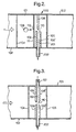
- Figure 2 is a longitudinal section of a second embodiment of the invention in which components which have the same function as corresponding components in the first embodiment of the invention have the same reference numerals.
- the lamina 109 of the field-enhancing electrodes is accompanied by a second similar lamina 109' separated from it by a gap 201 which communicates with a gas exit slit 202.
- the lamina 108 of the field enhancing electrodes is positioned opposite the gap 201 between the laminae 109, 109' and the membrane 105 is positioned adjacent the lamina 109 ' of the field-enhancing electrode so as to reduce the dead-space downstream of the field-enhancing electrodes.
- This form of microwave plasma generator produces an output of plasma excited gas in the form of a sheet, which is advantageous for some purposes such as the treatment of extended surfaces.
- gas input to the chamber may be via both sides of the field enhancing electrodes, that is, for example, using the configuration of ports shown in Figure 1, gas input via both ports 106 and 107. This further allows different gases to be introduced via the respective two ports. The gases may then react in the plasma formed between the field enhancing electrodes before exiting via gas exit slit 202.
- FIG 3 is a longitudinal section of a third embodiment of the invention in which the lamina 108 of the field-enhancing electrodes also is doubled and a gaseous medium to be energised is admitted into the chamber 101 via an inlet port 301 which communicates with the gap 302 between the laminae 108, 108'.
- This arrangement also provides that all the gaseous medium passes through the region of maximum electric field, so increasing the electrical efficiency of the plasma generator and also allowing the microwave entrance window membrane 104 to be brought close to the electric field-enhancing electrode as well as the microwave exit window membrane 105, so reducing the length of the plasma generator.
- the baffle 111 is redundant and is omitted.
- the doubled laminae have a symmetrical knife-edge as the laminae 108, 109 of the first embodiment of the invention, or an asymmetrical form as shown in Figures 2 and 3.
- the opposed edges of the field enhancing electrodes need not necessarily have a knife or sharp edge form, but may be flat.
- the thickness of the opposed edges of the electrodes is of the order of 1 mm to 2 mm but can be significantly more than this.
- Laminae providing the field enhancing electrodes can be of similar thickness, provided they are strong enough to resist buckling under the heat generated by the plasma. As indicated above, provision of coolant passages in the electrodes may be required, in which case a thicker structure will result.
- the width of gap between the electrodes is chosen so as to provide sufficient field enhancement for the plasma to strike at the required gas pressure of operation.
- a gap width of the order of 1 mm is required.
- a wider gap can be adopted.
- a modification may provide for the gap between the electrodes to be adjustable so that the plasma generator can readily be adapted for optimum operation for a given gas composition and operating pressure.
- Enhanced throughput of the gaseous medium allows the microwave plasma generator described herein suitable for the treatment of chemical warfare gases such as sarin, phosgene and other toxic components used in chemical weapons as well as the destruction of nerve agents and biological agents such as spores, for example anthrax spores, bacteria and viruses, naturally occurring or modified by genetic engineering techniques or combinations of chemical warfare gases and biological agents.
- the plasma generator may be incorporated into ventilation systems in buildings, fixed or portable, tents, bunkers above or below ground, ships, submarines, aircraft, vehicles. It may be part of a system for the detection and treatment of gases and agents.
- the system can include sensors for the detection of such gases and agents and these sensors can be based on microfabricated cantilevers for example as disclosed in WO99/38007 and WO 00/14539.
- the plasma generator can be run continuously or intermittently depending on the response of the sensor. Catalysts can be incorporated into the system downstream of the exhaust gases emitted from the plasma generator for the conversion of nitrogen oxides, produced in the plasma, to nitrogen.
- the plasma generator can also be used for the deactivation of prion proteins.
Landscapes
- Physics & Mathematics (AREA)
- Engineering & Computer Science (AREA)
- Plasma & Fusion (AREA)
- Chemical & Material Sciences (AREA)
- Analytical Chemistry (AREA)
- Physical Or Chemical Processes And Apparatus (AREA)
- Plasma Technology (AREA)
- Electron Sources, Ion Sources (AREA)
Claims (13)
- Mikrowellen-Plasmagenerator mit einer Kammer (101), die an eine Quelle für Mikrowellen-Strahlung gekoppelt ist, mit Einlaß- und Auslaßöffnungen (106, 107), durch welche ein in einen Plasmazustand zu erregendes gasförmiges Medium veranlaßt werden kann, durch die Kammer (101) zu strömen, und mit mindestens einem Paar von ein elektrisches Feld begünstigenden bzw. erhöhenden Elektroden (108, 109), dadurch gekennzeichnet, daß die das Feld erhöhenden Elektroden (108, 109) zwischen sich einen Spalt (110) bilden, der sich hauptsächlich linear im wesentlichen rechtwinklig zur Fortpflanzungsrichtung der Mikrowellen-Strahlung durch die Kammer (101) erstreckt, und daß der Spalt (110) so angeordnet ist, daß das durch die Kammer (101) strömende gasförmige Medium diesen Spalt (110) passiert.
- Mikrowellen-Plasmagenerator nach Anspruch 1, dadurch gekennzeichnet, daß die Auslaßöffnung (107) so geformt ist, daß das plasmaerregte gasförmige Medium in Form eines Blattes austritt.
- Mikrowellen-Plasmagenerator nach Anspruch 1 oder 2, dadurch gekennzeichnet, daß die sich gegenüberliegenden, den Spalt (110) bildenden Kanten der Elektroden (108, 109) einen spitz zulaufenden Querschnitt aufweisen.
- Mikrowellen-Plasmagenerator nach Anspruch 3, dadurch gekennzeichnet, daß die Querschnitte der einander gegenüberliegenden Kanten der Elektroden (108, 109) asymmetrisch sind.
- Mikrowellen-Plasmagenerator nach einem der vorangehenden Ansprüche, dadurch gekennzeichnet, daß mindestens eine Elektrode verdoppelt ist (108', 109'), um zwei parallel nebeneinander liegende ähnliche Elektrodenkomponenten vorzusehen.
- Mikrowellen-Plasmagenerator nach Anspruch 5, dadurch gekennzeichnet, daß der Raum zwischen der oder jeder der zwei benachbarten ähnlichen Elektrodenkomponenten mit einer Gasöffnung (202; 301) in Verbindung steht.
- Mikrowellen-Plasmagenerator nach Anspruch 6, dadurch gekennzeichnet, daß die Gasöffnung (202) oder mindestens die eine der Gasöffnungen (202; 301) von rechteckigem Querschnitt ist.
- Mikrowellen-Plasmagenerator nach Anspruch 6, dadurch gekennzeichnet, daß die Gasöffnung (20) von rechteckigem Querschnitt die Auslaßöffnung ist, um dadurch das ausströmende gasförmige Medium in Form eines Blattes vorzusehen.
- Mikrowellen-Plasmagenerator nach einem der vorangehenden Ansprüche, dadurch gekennzeichnet, daß die Elektroden aus einem Metall von hoher Wärmeleitfähigkeit hergestellt und mit einer Kante aus einem feuerfesten Material versehen sind.
- Mikrowellen-Plasmagenerator nach einem der vorangehenden Ansprüche, dadurch gekennzeichnet, daß die Elektroden mit Kanälen für den Durchfluß eines Kühlmittels versehen sind.
- Mikrowellen-Plasmagenerator nach einem der vorangehenden Ansprüche, dadurch gekennzeichnet, daß der genannte Spalt (110) eine gleichmäßige Breite über seine Länge hinweg aufweist.
- Mikrowellen-Plasmagenerator nach einem der Ansprüche 1 bis 10, bei dem die Breite des genannten Spaltes (110) in der Mitte größer ist und symmetrisch zu seinen Enden hin abnimmt.
- Mikrowellen-Plasmagenerator nach einem der vorangehenden Ansprüche, dadurch gekennzeichnet, daß die Elektroden oder Elektrodenkomponenten eine laminare Form haben.
Applications Claiming Priority (3)
| Application Number | Priority Date | Filing Date | Title |
|---|---|---|---|
| GBGB0126419.1A GB0126419D0 (en) | 2001-11-03 | 2001-11-03 | Microwave plasma generator |
| GB0126419 | 2001-11-03 | ||
| PCT/GB2002/004865 WO2003041111A1 (en) | 2001-11-03 | 2002-10-25 | Microwave plasma generator |
Publications (2)
| Publication Number | Publication Date |
|---|---|
| EP1449233A1 EP1449233A1 (de) | 2004-08-25 |
| EP1449233B1 true EP1449233B1 (de) | 2006-03-15 |
Family
ID=9925084
Family Applications (1)
| Application Number | Title | Priority Date | Filing Date |
|---|---|---|---|
| EP02770115A Expired - Lifetime EP1449233B1 (de) | 2001-11-03 | 2002-10-25 | Mikrowellen-plasmagenerator |
Country Status (7)
| Country | Link |
|---|---|
| US (1) | US7381290B2 (de) |
| EP (1) | EP1449233B1 (de) |
| JP (1) | JP2005509254A (de) |
| AT (1) | ATE320660T1 (de) |
| DE (1) | DE60209926D1 (de) |
| GB (1) | GB0126419D0 (de) |
| WO (1) | WO2003041111A1 (de) |
Families Citing this family (12)
| Publication number | Priority date | Publication date | Assignee | Title |
|---|---|---|---|---|
| JP2005235464A (ja) * | 2004-02-17 | 2005-09-02 | Toshio Goto | プラズマ発生装置 |
| GB0523947D0 (en) * | 2005-11-24 | 2006-01-04 | Boc Group Plc | Microwave plasma system |
| US7811665B2 (en) | 2008-02-29 | 2010-10-12 | The Procter & Gamble Compmany | Embossed fibrous structures |
| US7719694B1 (en) | 2008-06-23 | 2010-05-18 | Hrl Laboratories, Llc | System and method of surface wave imaging to detect ice on a surface or damage to a surface |
| US7931858B1 (en) | 2008-06-23 | 2011-04-26 | Hrl Laboratories, Llc | System and method for surface decontamination using electromagnetic surface waves |
| US8124013B1 (en) | 2008-06-23 | 2012-02-28 | Hrl Laboratories, Llc | System and method for large scale atmospheric plasma generation |
| US8009276B1 (en) | 2008-06-23 | 2011-08-30 | Hrl Laboratories, Llc | System and method of surface wave imaging to map pressure on a surface |
| US9752281B2 (en) * | 2010-10-27 | 2017-09-05 | The Procter & Gamble Company | Fibrous structures and methods for making same |
| US8932435B2 (en) * | 2011-08-12 | 2015-01-13 | Harris Corporation | Hydrocarbon resource processing device including radio frequency applicator and related methods |
| US9041408B2 (en) | 2013-01-16 | 2015-05-26 | Hrl Laboratories, Llc | Removable surface-wave networks for in-situ material health monitoring |
| CN112509901B (zh) * | 2020-11-19 | 2022-03-22 | 北京北方华创微电子装备有限公司 | 工艺腔室及半导体工艺设备 |
| US12009511B2 (en) | 2022-02-18 | 2024-06-11 | International Business Machines Corporation | Method to protect a lithium metal anode in a rechargeable lithium metal battery |
Family Cites Families (18)
| Publication number | Priority date | Publication date | Assignee | Title |
|---|---|---|---|---|
| US4393333A (en) * | 1979-12-10 | 1983-07-12 | Hitachi, Ltd. | Microwave plasma ion source |
| JPS6087200U (ja) * | 1983-11-15 | 1985-06-15 | 新日本無線株式会社 | マイクロ波プラズマ発生装置 |
| JPH0361371A (ja) * | 1989-07-28 | 1991-03-18 | Nec Corp | 薄膜形成装置 |
| DE69021821T2 (de) * | 1989-09-20 | 1996-05-30 | Sumitomo Electric Industries | Verfahren und Anlage zum Herstellen von Hartstoff. |
| US5425832A (en) * | 1990-10-05 | 1995-06-20 | Bridgestone Corporation | Surface treatment of fluoropolymer members and preparation of composite products therefrom |
| US5273587A (en) * | 1992-09-04 | 1993-12-28 | United Solar Systems Corporation | Igniter for microwave energized plasma processing apparatus |
| GB9224745D0 (en) * | 1992-11-26 | 1993-01-13 | Atomic Energy Authority Uk | Microwave plasma generator |
| WO1994017835A1 (en) * | 1993-02-02 | 1994-08-18 | United Kingdom Atomic Energy Authority | Gas activation |
| JP3147137B2 (ja) * | 1993-05-14 | 2001-03-19 | セイコーエプソン株式会社 | 表面処理方法及びその装置、半導体装置の製造方法及びその装置、並びに液晶ディスプレイの製造方法 |
| GB9414561D0 (en) * | 1994-07-19 | 1994-09-07 | Ea Tech Ltd | Method of and apparatus for microwave-plasma production |
| JPH09246251A (ja) * | 1996-03-01 | 1997-09-19 | Sony Corp | 半導体製造装置及び半導体製造方法 |
| US6388381B2 (en) * | 1996-09-10 | 2002-05-14 | The Regents Of The University Of California | Constricted glow discharge plasma source |
| EP0845287B1 (de) * | 1996-11-28 | 2003-12-17 | Accentus plc | Verfahren und Vorrichtung zur plasmachemischen Behandlung von Gasen |
| JPH11102901A (ja) * | 1997-09-26 | 1999-04-13 | Ricoh Co Ltd | マイクロ波励起ドライエッチング装置 |
| GB9801286D0 (en) | 1998-01-21 | 1998-03-18 | Univ Cambridge Tech | Sensor |
| GB9819319D0 (en) | 1998-09-05 | 1998-10-28 | Aea Technology Plc | Assay of chemical binding |
| US6204606B1 (en) | 1998-10-01 | 2001-03-20 | The University Of Tennessee Research Corporation | Slotted waveguide structure for generating plasma discharges |
| GB0021815D0 (en) * | 2000-09-06 | 2000-10-18 | Lofting Marcus J | Plasma enhanced gas reactor |
-
2001
- 2001-11-03 GB GBGB0126419.1A patent/GB0126419D0/en not_active Ceased
-
2002
- 2002-10-25 EP EP02770115A patent/EP1449233B1/de not_active Expired - Lifetime
- 2002-10-25 US US10/491,776 patent/US7381290B2/en not_active Expired - Lifetime
- 2002-10-25 JP JP2003543057A patent/JP2005509254A/ja active Pending
- 2002-10-25 AT AT02770115T patent/ATE320660T1/de not_active IP Right Cessation
- 2002-10-25 WO PCT/GB2002/004865 patent/WO2003041111A1/en not_active Ceased
- 2002-10-25 DE DE60209926T patent/DE60209926D1/de not_active Expired - Lifetime
Also Published As
| Publication number | Publication date |
|---|---|
| ATE320660T1 (de) | 2006-04-15 |
| DE60209926D1 (de) | 2006-05-11 |
| US7381290B2 (en) | 2008-06-03 |
| EP1449233A1 (de) | 2004-08-25 |
| WO2003041111A1 (en) | 2003-05-15 |
| US20040256056A1 (en) | 2004-12-23 |
| JP2005509254A (ja) | 2005-04-07 |
| GB0126419D0 (en) | 2002-01-02 |
Similar Documents
| Publication | Publication Date | Title |
|---|---|---|
| EP1449233B1 (de) | Mikrowellen-plasmagenerator | |
| Winter et al. | Atmospheric pressure plasma jets: an overview of devices and new directions | |
| KR100906836B1 (ko) | 플룸 안전성과 가열 효율이 향상된 마이크로파 플라즈마 노즐, 플라즈마 생성시스템 및 플라즈마 생성방법 | |
| US6126779A (en) | Plasma gas processing | |
| EP1371082B1 (de) | Corona ionenquelle | |
| AU2434201A (en) | Segmented electrode capillary discharge, non-thermal plasma apparatus and process for promoting chemical reactions | |
| KR20010040279A (ko) | 오염저감을 위한 모듈러 유전장벽 | |
| JPH06236800A (ja) | マイクロ波プラズマ発生器 | |
| US20240181385A1 (en) | Isolated plasma tube treatment systems | |
| US7931858B1 (en) | System and method for surface decontamination using electromagnetic surface waves | |
| JP5924696B2 (ja) | プラズマ処理装置 | |
| EP3900496B1 (de) | Vorrichtung zur behandlung von materialien mit plasma | |
| US9655986B2 (en) | Device and method for the treatment of a gaseous medium and use of the device for the treatment of a gaseous medium, liquid, solid, surface or any combination thereof | |
| US20060027539A1 (en) | Non-thermal plasma generator device | |
| KR100699699B1 (ko) | 고온 대용량 전자파 플라즈마 버너를 이용한 화생 독가스제거 장치 및 방법 | |
| Mizuno | Recent progress and applications of non-thermal plasma | |
| EP1638616B1 (de) | Verfahren zur dekontamination mit atomarem stickstoff | |
| Shukla | Nonlinear propagation of high-frequency plasma waves in a magnetized plasma | |
| CN200976707Y (zh) | 基于缩放通道结构的大气压放电冷等离子体发生器及阵列 | |
| EP2611521A1 (de) | Vorrichtung und verfahren zur behandlung eines gasförmigen mediums und verwendung der vorrichtung zur behandlung eines gasförmigen mediums, feststoffes, oberfläche oder einer kombination aus diesen | |
| Lee et al. | Computational study of a novel microwave electrothermal thruster using dielectric resonators (DRs) | |
| CZ304836B6 (cs) | Zařízení s akusticky stabilizovaným elektrickým výbojem | |
| Rader | An improved ionizer for atmospheric plasmas | |
| Liu et al. | Atmospheric pressure microwave-powered microplasma source based on strip-line structure | |
| CN111432545A (zh) | 一种等离子体发生器 |
Legal Events
| Date | Code | Title | Description |
|---|---|---|---|
| PUAI | Public reference made under article 153(3) epc to a published international application that has entered the european phase |
Free format text: ORIGINAL CODE: 0009012 |
|
| 17P | Request for examination filed |
Effective date: 20040324 |
|
| AK | Designated contracting states |
Kind code of ref document: A1 Designated state(s): AT BE BG CH CY CZ DE DK EE ES FI FR GB GR IE IT LI LU MC NL PT SE SK TR |
|
| AX | Request for extension of the european patent |
Extension state: AL LT LV MK RO SI |
|
| GRAP | Despatch of communication of intention to grant a patent |
Free format text: ORIGINAL CODE: EPIDOSNIGR1 |
|
| GRAS | Grant fee paid |
Free format text: ORIGINAL CODE: EPIDOSNIGR3 |
|
| GRAA | (expected) grant |
Free format text: ORIGINAL CODE: 0009210 |
|
| AK | Designated contracting states |
Kind code of ref document: B1 Designated state(s): AT BE BG CH CY CZ DE DK EE ES FI FR GB GR IE IT LI LU MC NL PT SE SK TR |
|
| PG25 | Lapsed in a contracting state [announced via postgrant information from national office to epo] |
Ref country code: BE Free format text: LAPSE BECAUSE OF FAILURE TO SUBMIT A TRANSLATION OF THE DESCRIPTION OR TO PAY THE FEE WITHIN THE PRESCRIBED TIME-LIMIT Effective date: 20060315 Ref country code: IT Free format text: LAPSE BECAUSE OF FAILURE TO SUBMIT A TRANSLATION OF THE DESCRIPTION OR TO PAY THE FEE WITHIN THE PRESCRIBED TIME-LIMIT;WARNING: LAPSES OF ITALIAN PATENTS WITH EFFECTIVE DATE BEFORE 2007 MAY HAVE OCCURRED AT ANY TIME BEFORE 2007. THE CORRECT EFFECTIVE DATE MAY BE DIFFERENT FROM THE ONE RECORDED. Effective date: 20060315 Ref country code: NL Free format text: LAPSE BECAUSE OF FAILURE TO SUBMIT A TRANSLATION OF THE DESCRIPTION OR TO PAY THE FEE WITHIN THE PRESCRIBED TIME-LIMIT Effective date: 20060315 Ref country code: SK Free format text: LAPSE BECAUSE OF FAILURE TO SUBMIT A TRANSLATION OF THE DESCRIPTION OR TO PAY THE FEE WITHIN THE PRESCRIBED TIME-LIMIT Effective date: 20060315 Ref country code: FI Free format text: LAPSE BECAUSE OF FAILURE TO SUBMIT A TRANSLATION OF THE DESCRIPTION OR TO PAY THE FEE WITHIN THE PRESCRIBED TIME-LIMIT Effective date: 20060315 Ref country code: LI Free format text: LAPSE BECAUSE OF FAILURE TO SUBMIT A TRANSLATION OF THE DESCRIPTION OR TO PAY THE FEE WITHIN THE PRESCRIBED TIME-LIMIT Effective date: 20060315 Ref country code: CH Free format text: LAPSE BECAUSE OF FAILURE TO SUBMIT A TRANSLATION OF THE DESCRIPTION OR TO PAY THE FEE WITHIN THE PRESCRIBED TIME-LIMIT Effective date: 20060315 Ref country code: AT Free format text: LAPSE BECAUSE OF FAILURE TO SUBMIT A TRANSLATION OF THE DESCRIPTION OR TO PAY THE FEE WITHIN THE PRESCRIBED TIME-LIMIT Effective date: 20060315 |
|
| REG | Reference to a national code |
Ref country code: GB Ref legal event code: FG4D Ref country code: CH Ref legal event code: EP |
|
| REG | Reference to a national code |
Ref country code: IE Ref legal event code: FG4D |
|
| REF | Corresponds to: |
Ref document number: 60209926 Country of ref document: DE Date of ref document: 20060511 Kind code of ref document: P |
|
| PG25 | Lapsed in a contracting state [announced via postgrant information from national office to epo] |
Ref country code: SE Free format text: LAPSE BECAUSE OF FAILURE TO SUBMIT A TRANSLATION OF THE DESCRIPTION OR TO PAY THE FEE WITHIN THE PRESCRIBED TIME-LIMIT Effective date: 20060615 Ref country code: BG Free format text: LAPSE BECAUSE OF FAILURE TO SUBMIT A TRANSLATION OF THE DESCRIPTION OR TO PAY THE FEE WITHIN THE PRESCRIBED TIME-LIMIT Effective date: 20060615 Ref country code: DK Free format text: LAPSE BECAUSE OF FAILURE TO SUBMIT A TRANSLATION OF THE DESCRIPTION OR TO PAY THE FEE WITHIN THE PRESCRIBED TIME-LIMIT Effective date: 20060615 |
|
| PG25 | Lapsed in a contracting state [announced via postgrant information from national office to epo] |
Ref country code: DE Free format text: LAPSE BECAUSE OF FAILURE TO SUBMIT A TRANSLATION OF THE DESCRIPTION OR TO PAY THE FEE WITHIN THE PRESCRIBED TIME-LIMIT Effective date: 20060617 |
|
| PG25 | Lapsed in a contracting state [announced via postgrant information from national office to epo] |
Ref country code: ES Free format text: LAPSE BECAUSE OF FAILURE TO SUBMIT A TRANSLATION OF THE DESCRIPTION OR TO PAY THE FEE WITHIN THE PRESCRIBED TIME-LIMIT Effective date: 20060626 |
|
| PG25 | Lapsed in a contracting state [announced via postgrant information from national office to epo] |
Ref country code: PT Free format text: LAPSE BECAUSE OF FAILURE TO SUBMIT A TRANSLATION OF THE DESCRIPTION OR TO PAY THE FEE WITHIN THE PRESCRIBED TIME-LIMIT Effective date: 20060816 |
|
| NLV1 | Nl: lapsed or annulled due to failure to fulfill the requirements of art. 29p and 29m of the patents act | ||
| REG | Reference to a national code |
Ref country code: CH Ref legal event code: PL |
|
| PG25 | Lapsed in a contracting state [announced via postgrant information from national office to epo] |
Ref country code: IE Free format text: LAPSE BECAUSE OF NON-PAYMENT OF DUE FEES Effective date: 20061025 |
|
| PG25 | Lapsed in a contracting state [announced via postgrant information from national office to epo] |
Ref country code: MC Free format text: LAPSE BECAUSE OF NON-PAYMENT OF DUE FEES Effective date: 20061031 |
|
| PLBE | No opposition filed within time limit |
Free format text: ORIGINAL CODE: 0009261 |
|
| STAA | Information on the status of an ep patent application or granted ep patent |
Free format text: STATUS: NO OPPOSITION FILED WITHIN TIME LIMIT |
|
| 26N | No opposition filed |
Effective date: 20061218 |
|
| EN | Fr: translation not filed | ||
| REG | Reference to a national code |
Ref country code: GB Ref legal event code: 732E |
|
| PG25 | Lapsed in a contracting state [announced via postgrant information from national office to epo] |
Ref country code: GR Free format text: LAPSE BECAUSE OF FAILURE TO SUBMIT A TRANSLATION OF THE DESCRIPTION OR TO PAY THE FEE WITHIN THE PRESCRIBED TIME-LIMIT Effective date: 20060616 Ref country code: CZ Free format text: LAPSE BECAUSE OF FAILURE TO SUBMIT A TRANSLATION OF THE DESCRIPTION OR TO PAY THE FEE WITHIN THE PRESCRIBED TIME-LIMIT Effective date: 20060315 Ref country code: FR Free format text: LAPSE BECAUSE OF FAILURE TO SUBMIT A TRANSLATION OF THE DESCRIPTION OR TO PAY THE FEE WITHIN THE PRESCRIBED TIME-LIMIT Effective date: 20070309 |
|
| PG25 | Lapsed in a contracting state [announced via postgrant information from national office to epo] |
Ref country code: EE Free format text: LAPSE BECAUSE OF FAILURE TO SUBMIT A TRANSLATION OF THE DESCRIPTION OR TO PAY THE FEE WITHIN THE PRESCRIBED TIME-LIMIT Effective date: 20060315 |
|
| PG25 | Lapsed in a contracting state [announced via postgrant information from national office to epo] |
Ref country code: LU Free format text: LAPSE BECAUSE OF NON-PAYMENT OF DUE FEES Effective date: 20061025 Ref country code: TR Free format text: LAPSE BECAUSE OF FAILURE TO SUBMIT A TRANSLATION OF THE DESCRIPTION OR TO PAY THE FEE WITHIN THE PRESCRIBED TIME-LIMIT Effective date: 20060315 |
|
| PG25 | Lapsed in a contracting state [announced via postgrant information from national office to epo] |
Ref country code: CY Free format text: LAPSE BECAUSE OF FAILURE TO SUBMIT A TRANSLATION OF THE DESCRIPTION OR TO PAY THE FEE WITHIN THE PRESCRIBED TIME-LIMIT Effective date: 20060315 Ref country code: FR Free format text: LAPSE BECAUSE OF FAILURE TO SUBMIT A TRANSLATION OF THE DESCRIPTION OR TO PAY THE FEE WITHIN THE PRESCRIBED TIME-LIMIT Effective date: 20060315 |
|
| PGFP | Annual fee paid to national office [announced via postgrant information from national office to epo] |
Ref country code: GB Payment date: 20211027 Year of fee payment: 20 |
|
| REG | Reference to a national code |
Ref country code: GB Ref legal event code: PE20 Expiry date: 20221024 |
|
| PG25 | Lapsed in a contracting state [announced via postgrant information from national office to epo] |
Ref country code: GB Free format text: LAPSE BECAUSE OF EXPIRATION OF PROTECTION Effective date: 20221024 |