EP1448868B1 - Selbstorientierende durchlöcherungsvorrichtung - Google Patents
Selbstorientierende durchlöcherungsvorrichtung Download PDFInfo
- Publication number
- EP1448868B1 EP1448868B1 EP02789928A EP02789928A EP1448868B1 EP 1448868 B1 EP1448868 B1 EP 1448868B1 EP 02789928 A EP02789928 A EP 02789928A EP 02789928 A EP02789928 A EP 02789928A EP 1448868 B1 EP1448868 B1 EP 1448868B1
- Authority
- EP
- European Patent Office
- Prior art keywords
- gun
- weight
- perforating
- tube
- gun tube
- Prior art date
- Legal status (The legal status is an assumption and is not a legal conclusion. Google has not performed a legal analysis and makes no representation as to the accuracy of the status listed.)
- Expired - Lifetime
Links
- 238000000034 method Methods 0.000 claims description 13
- 238000005474 detonation Methods 0.000 description 5
- 230000005484 gravity Effects 0.000 description 5
- 239000000463 material Substances 0.000 description 4
- 229910052751 metal Inorganic materials 0.000 description 3
- 239000002184 metal Substances 0.000 description 3
- 239000004215 Carbon black (E152) Substances 0.000 description 2
- 230000001351 cycling effect Effects 0.000 description 2
- 229930195733 hydrocarbon Natural products 0.000 description 2
- 150000002430 hydrocarbons Chemical class 0.000 description 2
- WFKWXMTUELFFGS-UHFFFAOYSA-N tungsten Chemical compound [W] WFKWXMTUELFFGS-UHFFFAOYSA-N 0.000 description 2
- 229910052721 tungsten Inorganic materials 0.000 description 2
- 239000010937 tungsten Substances 0.000 description 2
- JFALSRSLKYAFGM-UHFFFAOYSA-N uranium(0) Chemical compound [U] JFALSRSLKYAFGM-UHFFFAOYSA-N 0.000 description 2
- 229910000851 Alloy steel Inorganic materials 0.000 description 1
- 229910000975 Carbon steel Inorganic materials 0.000 description 1
- 229910000881 Cu alloy Inorganic materials 0.000 description 1
- 229910052770 Uranium Inorganic materials 0.000 description 1
- 239000010962 carbon steel Substances 0.000 description 1
- 238000010276 construction Methods 0.000 description 1
- 230000001419 dependent effect Effects 0.000 description 1
- 230000009969 flowable effect Effects 0.000 description 1
- 239000011133 lead Substances 0.000 description 1
- 238000004519 manufacturing process Methods 0.000 description 1
- 239000007769 metal material Substances 0.000 description 1
- 238000012986 modification Methods 0.000 description 1
- 230000004048 modification Effects 0.000 description 1
- 230000000979 retarding effect Effects 0.000 description 1
- 239000010935 stainless steel Substances 0.000 description 1
- 229910001220 stainless steel Inorganic materials 0.000 description 1
- XLYOFNOQVPJJNP-UHFFFAOYSA-N water Substances O XLYOFNOQVPJJNP-UHFFFAOYSA-N 0.000 description 1
- 238000003466 welding Methods 0.000 description 1
Images

Classifications
-
- E—FIXED CONSTRUCTIONS
- E21—EARTH OR ROCK DRILLING; MINING
- E21B—EARTH OR ROCK DRILLING; OBTAINING OIL, GAS, WATER, SOLUBLE OR MELTABLE MATERIALS OR A SLURRY OF MINERALS FROM WELLS
- E21B43/00—Methods or apparatus for obtaining oil, gas, water, soluble or meltable materials or a slurry of minerals from wells
- E21B43/11—Perforators; Permeators
- E21B43/119—Details, e.g. for locating perforating place or direction
Definitions
- the invention relates generally to the field of oil and gas well services. More specifically, the present invention relates to an apparatus that orients a tool into a desired position while the tool is in a deviated wellbore.
- orienting perforating guns in deviated wells enables the well operator to aim the shaped charges of the perforating gun at specific radial locations along the circumference of the wellbore. This is desired because the potential oil and gas producing zones of each specific well could exist at any radial position or region along the wellbore circumference. Based on the presence and location of these potential producing zones adjacent a deviated well, a well operator can discern a perforating gun orientation whose resulting perforations result in maximum hydrocarbon production.
- Daniel et al, U.S. Patent No. 4,410,051 discloses a system for orienting a perforating gun to be used in wells having multiple tubing strings.
- the apparatus of Daniel et al. '051 consists of a plurality of subassemblies connected end to end. Situated in one of the subassemblies is an eccentric weight sub that contains a weight positioned asymmetric to the longitudinal axis of the housing. Connected to the bottom of the eccentric weight sub is the alignment joint sub which is used to align the bottom portion of the housing with outlets of the perforating gun.
- the perforating gun section of the apparatus is disclosed as being below the eccentric weight sub. Wilkinson, U.S. Patent No.
- U.S. Patent Nos. 5,040,619 and 5,211,714 also disclose the use of an eccentrically weighted sub attached to a perforating gun to rotate the perforating gun inside of a deviates wellbore.
- George, U.S. Patent No. 4,637,478 involves a gravity oriented perforating gun for use in slanted wells comprised of one or more segments or subs, where each sub contains a center of gravity movement means which is a window that is cut out of the sub wall to alter the sub symmetry. Because it is asymmetric, the sub will rotate until the heavier portion of the sub circumference is below the lighter portion of the sub circumference.
- Henke et al. U.S. Patent No. 5,603,379, involves an apparatus for connecting and orienting perforating guns in a deviated well bore.
- the orientation aspect of the device consists of a fm longitudinally connected to the body of the perforating gun that positions the gun off center in the casing so that gravity will position the gun body at the bottom of the casing. Because of the positioning aspect of Henke '379, the perforations are generally directed into a downward trajectory.
- Vann, U.S. Patent Nos. 4,194,577 and 4,269,278 also disclose a perforating gun including longitudinal disposed fins on the gun outer circumference which act to direct the perforating charges in a downward pattern.
- Edwards et al. U.S. Patent No. 5,964,294, discloses a downhole tool for use in a deviated well constructed to rotate in response to a moment applied at its axis.
- the tool includes ballast chambers filled with a flowable ballast material to produce a gravitational force for rotating the tool.
- the ballast chambers are formed on the inner diameter of the loading tube assembly.
- the flowable ballast material consists of a high density metal such as tungsten or depleted uranium.
- Alternative embodiments include a multiple segmented tool where each tool has offset centers to produce rotation of the tool.
- One embodiment of the present invention discloses a system and method for orienting downhole tools, including perforating guns, into a specified orientation, while the tool is inside of a deviated or slanted wellbore.
- the tool comprises a perforating gun having a substantially cylindrical gun body with an inner and an outer diameter. Disposed within the gun body is a gun tube also with an inner and an outer diameter.
- the gun tube contains at least one shaped charge.
- Attached to the outer surface of the gun tube is a weight.
- Each weight has apertures formed therethrough that are aligned with each shaped charge so that the shot performance of each shaped charge is not affected by the attached weight during detonation.
- the attached weight can be equal to or less than the length of the gun tube.
- a method of aligning a perforating gun in a deviated wellbore comprises adapting a weight for attachment to the outer surface of a gun tube having one or more shaped charges. Radial locations along the weight are identified that coincide with the location of each shaped charge. Apertures through the weight are formed at each radial location. The weight is attached to the outer surface of gun tube such that the apertures are coaxially aligned with each shaped charge.
- the gun tube is placed into the gun body of a perforating gun, and the perforating gun containing the gun tube is inserted into the deviated section of a wellbore. When the rotation of the gun body caused by the Earth's gravitational force upon the eccentric weight has ceased, the shaped charges are ready to be detonated.
- the method also envisions receiving coordinates where perforations are desired within the wellbore.
- the weight is then strategically situated on the gun body such that rotation of the gun body caused by the Earth's gravitational force upon the weight orients the gun body so the shaped charges are aimed at the coordinates.
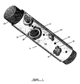
- FIG. 1 An internal oriented perforating system according to one embodiment of the present invention is shown in Figure 1.
- the perspective view of Figure 1 illustrates a gun tube 20 for use in a perforating system that incorporates one or more shaped charges 30 situated within the gun tube 20.
- the gun tube 20 is suitable for use in perforating subterranean wells, it is appreciated that one reasonably skilled in the art can produce a gun tube having shaped charges with ordinary effort and without undue experimentation.
- the gun tube 20 is a generally cylindrical elongated body with a range of lengths and diameters. While the length of the gun tube 20 of the present invention ranges from 4 feet to 28 feet, the advantages of the present invention can be enjoyed with a gun tube 20 of any length.
- the preferred diameters of the gun tube 20 are 2 3/4" (7cm) and 2" (5cm), however gun tubes of any diameter can be practiced as a part of this invention.
- the perforating system of the present invention involves the gun tube 20 disposed within a gun body 21, the gun body 21 having a slightly longer length than the gun tube 20 located therein. Often times individual perforating guns are connected end to end to create a perforating gun assembly. Because perforation operations can involve perforating a section of wellbore of less than 10 feet (3m) to over 10,000 feet (3000m), the length of the perforating gun assembly will vary accordingly.
- the perforating gun of the present invention can comprise a single gun tube 20 with a gun body 21, or multiple sections of the gun tube 20 and gun body 21.
- a swiveling connection (not shown) is used to connect multiple perforating guns into the perforating gun assembly. It is important that the connections allow the gun body 21 to rotate freely with respect to the connection and other gun bodies included in the perforating assembly.
- the weight 40 is generally semi-circular in cross section and includes apertures 41 formed at various locations along its body.
- the apertures 41 should be formed to be aligned with openings on the gun tube 20 where the shaped charge openings 31 and the shaped charge back 32 are located.
- the weight 40 can be formed from any material, the material should have a high density and be machinable. As such, the preferred materials include carbon steel, depleted uranium, tungsten, steel alloys, copper alloys, stainless steel, and lead.
- the shaped charge back 32 and the detonation cord 33 can extend past the outer circumference of the gun tube 20.
- the apertures 41 proximate to the shaped charge back 32 are created to tailor the weight 40 for a better fit onto the gun tube 20, while the apertures 41 proximate to the shaped charge openings 31 act to prevent the weight 40 from obstructing the discharge perforating jet produced by detonation of the shaped charges 30.
- the weight 40 attaches along a portion of the circumference of the gun tube 20 which produces an asymmetric structure.
- the gravitational forces acting on the weight 40 on both sides of the gun tube centerline 23 are equal.
- gravity cannot cause rotation of the gun tube 20.
- the center of gravity of the weight 40 is not directly below the gun tube center 22, the gravitational forces about the gun tube centerline 23 are not equal.
- the resulting imbalance will urge the weight 40 downward until the center of gravity of the weight 40 is directly below the gun tube center 22, i.e. or until the gravitational forces applied to the weight 40 on either side of the gun tube center 22 are equal. When this occurs the weight 40.is at its "low point.”
- one or more perforating guns of the present invention are assembled and inserted into a well that is to be perforated. Inserting the present invention into a wellbore can be done with a conventional wireline, in conjunction with a tractor sub, or can be tubing conveyed. When the perforating gun reaches a deviated or slanted portion of the well, the gravitational forces will act upon the eccentric weight 40 until the weight 40 is in the low position. Prior to assembly the wellbore technical personnel evaluate how the shaped charges 30 should be aimed based on potential producing zones adjacent the wellbore. The gun tube 20 orientation during detonation is dependent upon how the shaped charges should be aimed during the perforation sequence.
- the weight 40 should be attached such that its eccentrically loaded mass can rotate the gun tube 20 into the desired orientation.
- apertures 41 are formed through the weight 40 so that the weight 40 will not cover the shaped charge opening 31 or the shaped charge back 32.
- the perforating gun As the perforating gun is put into position for detonating the shaped charges, it will be cycled up and down inside of the wellbore to provide some mechanical force impulses to the gun tube 20. These impulses can shake the gun tube 20 and further ensure that the weight 40 has rotated into a low position. Cycling the perforation gun may be more important in instances where the deviated section of the wellbore exceeds 15° to 20° from horizontal, or if some foreign matter has become stuck between the gun tube 20 and the gun body 21, thereby retarding rotation of the gun tube 20 inside of the gun body 21.
- the well operator positions the perforation gun to the depth inside of the wellbore where perforations are to be made. When the perforation gun is at the proper depth, the shaped charges 30 will be detonated thereby perforating the wellbore.
- Alternative embodiments of eccentrically loading a perforating gun include introducing a semi-cylindrical gun tube that is asymmetric about its longitudinal axis.
- the asymmetry of the gun tube in and of itself eccentrically weights the perforating gun so that when non-vertical the perforating gun will rotate in response to gravitational pulls on the eccentric loading.
- Another alternative embodiment involves creating longitudinal recesses along sections of the gun tube 21 and adding metal rods or bars into those recesses. The presence of the metal rods or bars will produce an asymmetry that also can rotate the perforating gun.
- the recesses should be located in the same hemispherical section of the gun tube 21 to produce an eccentrically loaded situation.
- a yet additional alternative embodiment exists where asymmetry of the gun body 20 is developed by securing the gun tube 21 inside of the gun body 20 at or proximate to the inner circumference gun body 20 and not coaxial within the gun body 20.
Landscapes
- Geology (AREA)
- Life Sciences & Earth Sciences (AREA)
- Engineering & Computer Science (AREA)
- Mining & Mineral Resources (AREA)
- Environmental & Geological Engineering (AREA)
- Fluid Mechanics (AREA)
- Physics & Mathematics (AREA)
- General Life Sciences & Earth Sciences (AREA)
- Geochemistry & Mineralogy (AREA)
- Coating By Spraying Or Casting (AREA)
- Drilling Tools (AREA)
- Processing Of Stones Or Stones Resemblance Materials (AREA)
- Materials For Medical Uses (AREA)
- Earth Drilling (AREA)
- Image Generation (AREA)
Claims (20)
- Perforierende Schussvorrichtung zum Einsatz in einem Bohrloch mit wenigstens einem im Wesentlichen zylindrischen Schussvorrichtungskörper (21), der um seine Längsachse drehbar ist und einen Innen- und einen Außenumfang aufweist, einem im Wesentlichen zylindrischen Schussvorrichtungsrohr (20), das innerhalb des Schussvorrichtungskörpers (21) angeordnet ist, wobei das Schussvorrichtungsrohr (20) einen Innen- und einen Außenumfang aufweist und wenigstens eine geformte Ladung (30) enthält, und
wenigstens einem Gewicht (40), das die perforierende Schussvorrichtung bezüglich ihrer Längsachse exzentrisch belastet,
dadurch gekennzeichnet, dass das Gewicht (40) an der Außenfläche des Schussvorrichtungsrohrs (20) angeordnet ist und durch es hindurch ausgebildete Öffnungen (41) aufweist, die zu einer geformten Ladung (30) ausgerichtet sind. - Perforierende Schussvorrichtung nach Anspruch 1, bei der das Gewicht (40) entlang der gesamten Länge des Schussvorrichtungsrohrs (20) angeordnet ist.
- Perforierende Schussvorrichtung nach Anspruch 1, bei der das Gewicht (40) entlang eines Abschnitts des Schussvorrichtungsrohrs (20) angeordnet ist.
- Perforierende Schussvorrichtung nach einem der vorhergehenden Ansprüche, bei der die Öffnungen (41) koaxial um jede geformte Ladung (30) angeordnet sind, ohne die Funktion der geformten Ladungen (30) zu beeinträchtigen.
- Perforierende Schussvorrichtung nach einem der vorhergehenden Ansprüche, bei der das Gewicht (40) eine ausreichende Masse aufweist, so dass die exzentrische Belastung von dem Gewicht (40) die perforierende Schussvorrichtung um ihre Längsachse in Ansprechung auf Schwerkräfte drehen kann, die auf das Gewicht (40) aufgebracht werden.
- Perforierende Schussvorrichtung nach einem der vorhergehenden Ansprüche, bei der das Gewicht (40) zwischen dem Innenumfang des Schussvorrichtungskörpers (21) und dem Außenumfang des Schussvorrichtungsrohrs (20) angeordnet ist.
- Perforierende Schussvorrichtung mit
einer Vielzahl vom im Wesentlichen zylindrischen Schussvorrichtungskörpern (21), die um ihre Längsachse drehbar sind, wobei jeder der Schussvorrichtungskörper (21) einen Innen- und einen Außenumfang aufweist,
wobei jeder Schussvorrichtungskörper (21) wenigstens ein im Wesentlichen zylindrisches Schussvorrichtungsrohr (20) aufweist, das innerhalb des Schussvorrichtungskörpers (21) verbindend angeordnet ist, wobei jedes Schussvorrichtungsrohr (20) einen Innen- und einen Außenumfang aufweist und wenigstens eine geformte Ladung (30) enthält, und
wenigstens einem Gewicht (40), das die perforierende Schussvorrichtung bezüglich seiner Längsachse exzentrisch belastet,
dadurch gekennzeichnet, dass das Gewicht (40) an der Außenfläche des Schussvorrichtungsrohrs (20) angeordnet ist und durch es hindurch ausgebildete Öffnungen (41) aufweist, die zu einer geformten Ladung (30) ausgerichtet sind. - Perforierende Schussvorrichtung nach Anspruch 7, bei der das Gewicht (40) entlang der gesamten Länge des Schussvorrichtungsrohrs (20) angeordnet ist.
- Perforierende Schussvorrichtung nach Anspruch 7, bei der das Gewicht (40) entlang eines Abschnitts des Schussvorrichtungsrohrs (20) angeordnet ist.
- Perforierende Schussvorrichtung nach einem der Ansprüche 7 bis 9, bei der die Öffnungen (41) koaxial um jede geformte Ladung (30) angeordnet sind, ohne die Funktion der geformten Ladungen (30) zu beeinträchtigen.
- Perforierende Schussvorrichtung nach einem der Ansprüche 7 bis 10, bei der das Gewicht (40) eine ausreichende Masse aufweist, so dass die exzentrische Belastung die perforierende Schussvorrichtung um ihre Längsachse in Ansprechung auf Schwerkräfte drehen kann, die auf das Gewicht (40) aufgebracht werden.
- Perforierende Schussvorrichtung nach einem der Ansprüche 7 bis 11, die außerdem Zapfenverbinder aufweist, durch die Schussvorrichtungskörper (21) Ende an Ende verbunden werden.
- Perforierende Schussvorrichtung nach einem der Ansprüche 7 bis 12, bei der jedes Gewicht (40) zwischen dem Innenumfang jedes Schussvorrichtungskörpers (21) und dem Außenumfang jedes Schussvorrichtungsrohrs (20) angeordnet ist.
- Verfahren zur Ausrichtung einer perforierenden Schussvorrichtung in einem abgelenkten Bohrloch mit den Schritten:Anpassung eines halbzylindrischen exzentrischen Gewichts (40) für eine Befestigung an einem Schussvorrichtungsrohr (20), das eine oder mehrere geformte Ladungen (30) aufweist;Identifizierung radialer Orte entlang des exzentrischen Gewichts (40), die mit dem Ort jeder der geformten Ladungen (30) übereinstimmen;Bildung von Öffnungen (41) durch die exzentrischen Gewichte (40) an jedem der radialen Orte;Befestigung des exzentrischen Gewichts (40) an der Außenfläche des Schussvorrichtungsrohrs (20), so dass die Öffnungen (41) koaxial zu jeder geformten Ladung (30) ausgerichtet sind;Platzierung des Schussvorrichtungsrohrs (20) in einem Schussvorrichtungskörper (21) einer perforierenden Schussvorrichtung und Einsetzen der perforierenden Schussvorrichtung, die das Schussvorrichtungsrohr (20) enthält, in einen abgelenkten Abschnitt eines Bohrlochs;Warten bis die Drehung des Schussvorrichtungskörpers (21), die durch die Schwerkraft der Erde auf das exzentrische Gewicht (40) verursacht wurde, aufhört; und Zünden jeder der einen oder mehreren geformten Ladungen (30).
- Verfahren nach Anspruch 14, das außerdem die Auswahl von Orten innerhalb eines abgelenkten Bohrlochs umfasst, an denen die Perforationen liegen sollen.
- Verfahren nach Anspruch 14, dass außerdem die Positionierung des exzentrischen Gewichts (40) an einem strategisch gelegenen Punkt auf dem Schussvorrichtungsrohr (20) umfasst, so dass eine Drehung des Schussvorrichtungskörpers (21), die durch die Schwerkraft der Erde auf das exzentrische Gewicht (40) verursacht wurde, den Schussvorrichtungskörper (21) so orientiert, dass die geformten Ladungen (30) auf die Perforationsorte gerichtet werden.
- Verfahren nach Anspruch 14, das außerdem die Sicherstellung einer freien Drehung des Schussvorrichtungskörpers (20) umfasst, an dem ein exzentrisches Gewicht (40) innerhalb des Schussvorrichtungskörpers (21) befestigt ist.
- Verfahren nach Anspruch 14, das außerdem die Ausbildung des exzentrischen Gewichts (40) mit einer Länge umfasst, die gleich der Länge des Schussvorrichtungsrohrs (20) ist.
- Verfahren nach Anspruch 14, das außerdem die Ausbildung des exzentrischen Gewichts (40) mit einer Länge umfasst, die geringer ist als die Länge des Schussvorrichtungsrohrs (20).
- Verfahren nach Anspruch 14, das außerdem die Ausbildung der Öffnungen (41) zur Sicherstellung umfasst, dass die Funktion jeder der geformten Ladungen (30) nicht beeinflusst wird.
Applications Claiming Priority (3)
| Application Number | Priority Date | Filing Date | Title |
|---|---|---|---|
| US21799 | 2001-11-30 | ||
| US10/021,799 US6679327B2 (en) | 2001-11-30 | 2001-11-30 | Internal oriented perforating system and method |
| PCT/US2002/038184 WO2003048523A1 (en) | 2001-11-30 | 2002-11-27 | Internally oriented perforating system |
Publications (2)
| Publication Number | Publication Date |
|---|---|
| EP1448868A1 EP1448868A1 (de) | 2004-08-25 |
| EP1448868B1 true EP1448868B1 (de) | 2006-05-17 |
Family
ID=21806217
Family Applications (1)
| Application Number | Title | Priority Date | Filing Date |
|---|---|---|---|
| EP02789928A Expired - Lifetime EP1448868B1 (de) | 2001-11-30 | 2002-11-27 | Selbstorientierende durchlöcherungsvorrichtung |
Country Status (8)
| Country | Link |
|---|---|
| US (1) | US6679327B2 (de) |
| EP (1) | EP1448868B1 (de) |
| AU (1) | AU2002352968B2 (de) |
| BR (1) | BR0214580B1 (de) |
| CA (1) | CA2468731C (de) |
| EA (1) | EA005840B1 (de) |
| NO (1) | NO335422B1 (de) |
| WO (1) | WO2003048523A1 (de) |
Families Citing this family (65)
| Publication number | Priority date | Publication date | Assignee | Title |
|---|---|---|---|---|
| US7114564B2 (en) * | 2001-04-27 | 2006-10-03 | Schlumberger Technology Corporation | Method and apparatus for orienting perforating devices |
| GB2374887B (en) * | 2001-04-27 | 2003-12-17 | Schlumberger Holdings | Method and apparatus for orienting perforating devices |
| US7152676B2 (en) * | 2002-10-18 | 2006-12-26 | Schlumberger Technology Corporation | Techniques and systems associated with perforation and the installation of downhole tools |
| US6865978B2 (en) * | 2002-12-05 | 2005-03-15 | Edward C. Kash | Well perforating gun |
| US7055421B2 (en) * | 2003-02-18 | 2006-06-06 | Edward Cannoy Kash | Well perforating gun |
| US6865792B2 (en) | 2003-02-18 | 2005-03-15 | Edward Cannoy Kash | Method for making a well perforating gun |
| US6926096B2 (en) | 2003-02-18 | 2005-08-09 | Edward Cannoy Kash | Method for using a well perforating gun |
| WO2005005094A1 (en) * | 2003-07-01 | 2005-01-20 | G & H Diversified Manufacturing, Lp | Well perforating gun |
| DE102004043948A1 (de) * | 2003-09-27 | 2005-05-25 | Dynaenergetics Gmbh & Co. Kg | Perforationskanonensystem mit selbstverschließenden Durchschusslöchern |
| US7607379B2 (en) * | 2003-09-27 | 2009-10-27 | Dynaenergetics Gmbh & Co. Kg | Perforation gun system for sealing perforation holes |
| US7610969B2 (en) * | 2006-05-26 | 2009-11-03 | Owen Oil Tools Lp | Perforating methods and devices for high wellbore pressure applications |
| CN200975243Y (zh) * | 2006-12-06 | 2007-11-14 | 西安通源石油科技股份有限公司 | 水平井射孔器的配重装置 |
| US8365814B2 (en) * | 2007-09-20 | 2013-02-05 | Baker Hughes Incorporated | Pre-verification of perforation alignment |
| US8186259B2 (en) * | 2007-12-17 | 2012-05-29 | Halliburton Energy Sevices, Inc. | Perforating gun gravitational orientation system |
| US8127848B2 (en) * | 2008-03-26 | 2012-03-06 | Baker Hughes Incorporated | Selectively angled perforating |
| US7861778B2 (en) * | 2008-07-15 | 2011-01-04 | Baker Hughes Incorporated | Pressure orienting swivel arrangement and method |
| US7752971B2 (en) * | 2008-07-17 | 2010-07-13 | Baker Hughes Incorporated | Adapter for shaped charge casing |
| EA014439B1 (ru) * | 2008-10-31 | 2010-12-30 | Салават Анатольевич Кузяев | Устройство для перфорации скважины |
| US7934558B2 (en) * | 2009-03-13 | 2011-05-03 | Halliburton Energy Services, Inc. | System and method for dynamically adjusting the center of gravity of a perforating apparatus |
| WO2010111638A2 (en) * | 2009-03-26 | 2010-09-30 | Baker Hughes Incorporated | Pressure compensation for a perforating gun |
| US8327746B2 (en) * | 2009-04-22 | 2012-12-11 | Schlumberger Technology Corporation | Wellbore perforating devices |
| US8839863B2 (en) * | 2009-05-04 | 2014-09-23 | Baker Hughes Incorporated | High pressure/deep water perforating system |
| GB201009781D0 (en) * | 2010-06-11 | 2010-07-21 | Expro North Sea Ltd | Perforating gun and method of perforating a well |
| US8397800B2 (en) | 2010-12-17 | 2013-03-19 | Halliburton Energy Services, Inc. | Perforating string with longitudinal shock de-coupler |
| US8393393B2 (en) | 2010-12-17 | 2013-03-12 | Halliburton Energy Services, Inc. | Coupler compliance tuning for mitigating shock produced by well perforating |
| US8397814B2 (en) | 2010-12-17 | 2013-03-19 | Halliburton Energy Serivces, Inc. | Perforating string with bending shock de-coupler |
| US8985200B2 (en) | 2010-12-17 | 2015-03-24 | Halliburton Energy Services, Inc. | Sensing shock during well perforating |
| WO2012148429A1 (en) | 2011-04-29 | 2012-11-01 | Halliburton Energy Services, Inc. | Shock load mitigation in a downhole perforation tool assembly |
| MX2013006899A (es) | 2010-12-17 | 2013-07-17 | Halliburton Energy Serv Inc | Perforacion del pozo con determinacion de caracteristicas del pozo. |
| US20120241169A1 (en) | 2011-03-22 | 2012-09-27 | Halliburton Energy Services, Inc. | Well tool assemblies with quick connectors and shock mitigating capabilities |
| US9689223B2 (en) | 2011-04-01 | 2017-06-27 | Halliburton Energy Services, Inc. | Selectable, internally oriented and/or integrally transportable explosive assemblies |
| US8746331B2 (en) | 2011-08-11 | 2014-06-10 | Edward Cannoy Kash | Rust resistant well perforating gun with gripping surfaces |
| US9091152B2 (en) | 2011-08-31 | 2015-07-28 | Halliburton Energy Services, Inc. | Perforating gun with internal shock mitigation |
| US9297228B2 (en) | 2012-04-03 | 2016-03-29 | Halliburton Energy Services, Inc. | Shock attenuator for gun system |
| US8978749B2 (en) | 2012-09-19 | 2015-03-17 | Halliburton Energy Services, Inc. | Perforation gun string energy propagation management with tuned mass damper |
| WO2014046656A1 (en) | 2012-09-19 | 2014-03-27 | Halliburton Energy Services, Inc. | Perforation gun string energy propagation management system and methods |
| WO2014084868A1 (en) | 2012-12-01 | 2014-06-05 | Halliburton Energy Services, Inc. | Protection of electronic devices used with perforating guns |
| MX375593B (es) | 2014-02-12 | 2025-03-06 | Owen Oil Tools Lp | Cañon de perforacion con tubo de carga giratorio excentrico. |
| RU2648406C1 (ru) * | 2017-02-10 | 2018-03-26 | Публичное акционерное общество "Татнефть" имени В.Д. Шашина | Устройство для локального разрыва пласта |
| US11414965B2 (en) | 2018-02-27 | 2022-08-16 | Schlumberger Technology Corporation | Rotating loading tube and angled shaped charges for oriented perforating |
| US11078762B2 (en) | 2019-03-05 | 2021-08-03 | Swm International, Llc | Downhole perforating gun tube and components |
| US10689955B1 (en) | 2019-03-05 | 2020-06-23 | SWM International Inc. | Intelligent downhole perforating gun tube and components |
| US12291945B1 (en) | 2019-03-05 | 2025-05-06 | Swm International, Llc | Downhole perforating gun system |
| US11326410B2 (en) | 2019-03-14 | 2022-05-10 | Frac Innovation Llc | Orienting sub for well instruments |
| US11268376B1 (en) | 2019-03-27 | 2022-03-08 | Acuity Technical Designs, LLC | Downhole safety switch and communication protocol |
| US10927627B2 (en) | 2019-05-14 | 2021-02-23 | DynaEnergetics Europe GmbH | Single use setting tool for actuating a tool in a wellbore |
| US11255147B2 (en) | 2019-05-14 | 2022-02-22 | DynaEnergetics Europe GmbH | Single use setting tool for actuating a tool in a wellbore |
| US11578549B2 (en) | 2019-05-14 | 2023-02-14 | DynaEnergetics Europe GmbH | Single use setting tool for actuating a tool in a wellbore |
| US12241326B2 (en) | 2019-05-14 | 2025-03-04 | DynaEnergetics Europe GmbH | Single use setting tool for actuating a tool in a wellbore |
| WO2020249744A2 (en) | 2019-06-14 | 2020-12-17 | DynaEnergetics Europe GmbH | Perforating gun assembly with rotating shaped charge holder |
| WO2021122797A1 (en) | 2019-12-17 | 2021-06-24 | DynaEnergetics Europe GmbH | Modular perforating gun system |
| US11619119B1 (en) | 2020-04-10 | 2023-04-04 | Integrated Solutions, Inc. | Downhole gun tube extension |
| US11326442B1 (en) | 2020-11-09 | 2022-05-10 | Halliburton Energy Services, Inc. | Orientation verification devices |
| US11512565B2 (en) * | 2020-12-01 | 2022-11-29 | Halliburton Energy Services, Inc. | Plastic weight assembly for downhole perforating gun |
| CN112593903A (zh) * | 2020-12-14 | 2021-04-02 | 大庆石油管理局有限公司 | 一种定射角内盲孔射孔枪 |
| US11732556B2 (en) | 2021-03-03 | 2023-08-22 | DynaEnergetics Europe GmbH | Orienting perforation gun assembly |
| US12366142B2 (en) | 2021-03-03 | 2025-07-22 | DynaEnergetics Europe GmbH | Modular perforating gun system |
| US12584363B2 (en) | 2021-04-22 | 2026-03-24 | GR Energy Services, Management, LP | Orientable weight bar for a downhole tool and method of using same |
| US12000267B2 (en) | 2021-09-24 | 2024-06-04 | DynaEnergetics Europe GmbH | Communication and location system for an autonomous frack system |
| MX2023008154A (es) | 2022-01-09 | 2023-07-21 | Gr Energy Services Man L P | Sistema de monitoreo de pozo con un rastreador de pozos y metodo de uso del mismo. |
| WO2023200984A1 (en) | 2022-04-15 | 2023-10-19 | Dbk Industries, Llc | Fixed-volume setting tool |
| US11753889B1 (en) | 2022-07-13 | 2023-09-12 | DynaEnergetics Europe GmbH | Gas driven wireline release tool |
| WO2024013338A1 (en) | 2022-07-13 | 2024-01-18 | DynaEnergetics Europe GmbH | Gas driven wireline release tool |
| US20240401441A1 (en) * | 2023-05-31 | 2024-12-05 | Gr Energy Services Management, Lp | Orientable perforating gun with orienting bearing assembly and method of using same |
| US12612844B2 (en) * | 2024-01-08 | 2026-04-28 | Halliburton Energy Services, Inc. | Systems and methods for real time oil tool orientation detection |
Family Cites Families (28)
| Publication number | Priority date | Publication date | Assignee | Title |
|---|---|---|---|---|
| US2326405A (en) * | 1941-06-02 | 1943-08-10 | Lane Wells Co | Side-wall sampling device for well bores |
| US3049185A (en) * | 1956-12-26 | 1962-08-14 | Paul O Tobeler | Method for oscillating drilling |
| US3167137A (en) | 1961-12-19 | 1965-01-26 | Texaco Inc | Weighted drill collar |
| US3361204A (en) * | 1965-06-25 | 1968-01-02 | Pan American Petroleum Corp | Method and apparatus for treating an underground formation |
| US3730282A (en) | 1971-03-11 | 1973-05-01 | Shell Oil Co | Mechanically oriented perforating system |
| US4269278A (en) | 1977-10-17 | 1981-05-26 | Peabody Vann | Method and apparatus for completing a slanted wellbore |
| US4194577A (en) | 1977-10-17 | 1980-03-25 | Peabody Vann | Method and apparatus for completing a slanted wellbore |
| US4278138A (en) | 1980-01-21 | 1981-07-14 | Christensen, Inc. | Composite heavy metal drill collar |
| US4410051A (en) | 1981-02-27 | 1983-10-18 | Dresser Industries, Inc. | System and apparatus for orienting a well casing perforating gun |
| FR2508538A1 (fr) | 1981-06-30 | 1982-12-31 | Schlumberger Prospection | Dispositif de perforation pour sondage |
| US4438810A (en) | 1981-10-26 | 1984-03-27 | Dresser Industries, Inc. | Apparatus for decentralizing and orienting a well logging or perforating instrument |
| GB2128719B (en) | 1982-10-20 | 1986-11-26 | Vann Inc Geo | Gravity oriented perforating gun for use in slanted boreholes |
| AU570233B2 (en) | 1983-02-18 | 1988-03-10 | Bowater Tutt Industries Pty. Ltd. | Vibratory mechanism |
| US4523649A (en) | 1983-05-25 | 1985-06-18 | Baker Oil Tools, Inc. | Rotational alignment method and apparatus for tubing conveyed perforating guns |
| US4830120A (en) | 1988-06-06 | 1989-05-16 | Baker Hughes Incorporated | Methods and apparatus for perforating a deviated casing in a subterranean well |
| US4844161A (en) | 1988-08-18 | 1989-07-04 | Halliburton Logging Services, Inc. | Locking orientation sub and alignment housing for drill pipe conveyed logging system |
| JP2554528B2 (ja) | 1988-09-19 | 1996-11-13 | 大塚製薬株式会社 | 副腎皮質刺激ホルモン分泌能検査薬 |
| US5010964A (en) | 1990-04-06 | 1991-04-30 | Atlantic Richfield Company | Method and apparatus for orienting wellbore perforations |
| US5033553A (en) | 1990-04-12 | 1991-07-23 | Schlumberger Technology Corporation | Intra-perforating gun swivel |
| US5211714A (en) | 1990-04-12 | 1993-05-18 | Halliburton Logging Services, Inc. | Wireline supported perforating gun enabling oriented perforations |
| US5040619A (en) | 1990-04-12 | 1991-08-20 | Halliburton Logging Services, Inc. | Wireline supported perforating gun enabling oriented perforations |
| US5103912A (en) | 1990-08-13 | 1992-04-14 | Flint George R | Method and apparatus for completing deviated and horizontal wellbores |
| US5107927A (en) | 1991-04-29 | 1992-04-28 | Otis Engineering Corporation | Orienting tool for slant/horizontal completions |
| US5273121A (en) | 1992-04-03 | 1993-12-28 | Eastern Oil Tools Pte Ltd. | Intercarrier mechanism for connecting and orienting tubing conveyed perforating guns |
| US5484029A (en) | 1994-08-05 | 1996-01-16 | Schlumberger Technology Corporation | Steerable drilling tool and system |
| EP0703348B1 (de) | 1994-08-31 | 2003-10-15 | HALLIBURTON ENERGY SERVICES, Inc. | Vorrichtung zum Verbinden von Perforatoren im Bohrloch |
| US5964294A (en) | 1996-12-04 | 1999-10-12 | Schlumberger Technology Corporation | Apparatus and method for orienting a downhole tool in a horizontal or deviated well |
| GB2374887B (en) | 2001-04-27 | 2003-12-17 | Schlumberger Holdings | Method and apparatus for orienting perforating devices |
-
2001
- 2001-11-30 US US10/021,799 patent/US6679327B2/en not_active Expired - Lifetime
-
2002
- 2002-11-27 CA CA002468731A patent/CA2468731C/en not_active Expired - Fee Related
- 2002-11-27 EA EA200400705A patent/EA005840B1/ru not_active IP Right Cessation
- 2002-11-27 BR BRPI0214580-4A patent/BR0214580B1/pt not_active IP Right Cessation
- 2002-11-27 EP EP02789928A patent/EP1448868B1/de not_active Expired - Lifetime
- 2002-11-27 WO PCT/US2002/038184 patent/WO2003048523A1/en not_active Ceased
- 2002-11-27 AU AU2002352968A patent/AU2002352968B2/en not_active Ceased
-
2004
- 2004-06-29 NO NO20042747A patent/NO335422B1/no not_active IP Right Cessation
Also Published As
| Publication number | Publication date |
|---|---|
| WO2003048523A1 (en) | 2003-06-12 |
| AU2002352968B2 (en) | 2008-05-15 |
| BR0214580B1 (pt) | 2012-11-27 |
| NO20042747L (no) | 2004-08-30 |
| EP1448868A1 (de) | 2004-08-25 |
| CA2468731C (en) | 2008-04-01 |
| EA005840B1 (ru) | 2005-06-30 |
| BR0214580A (pt) | 2004-11-03 |
| US6679327B2 (en) | 2004-01-20 |
| US20030102162A1 (en) | 2003-06-05 |
| CA2468731A1 (en) | 2003-06-12 |
| EA200400705A1 (ru) | 2004-12-30 |
| AU2002352968A1 (en) | 2003-06-17 |
| NO335422B1 (no) | 2014-12-15 |
Similar Documents
| Publication | Publication Date | Title |
|---|---|---|
| CA2468731C (en) | Internally oriented perforating system | |
| US7621342B2 (en) | Method for retaining debris in a perforating apparatus | |
| EP2410122B1 (de) | System und Verfahren zur dynamischen Anpassung des Schwerpunkts einer Perforiervorrichtung | |
| EP0929732B1 (de) | Bohrlochperforationssystem hoher dichte | |
| US7237486B2 (en) | Low debris perforating gun system for oriented perforating | |
| US7237487B2 (en) | Low debris perforating gun system for oriented perforating | |
| US20150226043A1 (en) | Limited Entry Phased Preforating Gun System and Method | |
| US7044236B2 (en) | Shot direction indicating device | |
| US7360599B2 (en) | Debris reduction perforating apparatus and method for use of same | |
| CA2931918A1 (en) | Limited entry phased perforating gun system and method | |
| EP3245381B1 (de) | System und verfahren für phasengesteuerte perforationspistole mit begrenzter eingabe |
Legal Events
| Date | Code | Title | Description |
|---|---|---|---|
| PUAI | Public reference made under article 153(3) epc to a published international application that has entered the european phase |
Free format text: ORIGINAL CODE: 0009012 |
|
| 17P | Request for examination filed |
Effective date: 20040608 |
|
| AK | Designated contracting states |
Kind code of ref document: A1 Designated state(s): AT BE BG CH CY CZ DE DK EE ES FI FR GB GR IE IT LI LU MC NL PT SE SK TR |
|
| AX | Request for extension of the european patent |
Extension state: AL LT LV MK RO SI |
|
| RIN1 | Information on inventor provided before grant (corrected) |
Inventor name: RANTALA, ERICK, R. Inventor name: SLOAN, MARK, L. |
|
| 17Q | First examination report despatched |
Effective date: 20050215 |
|
| REG | Reference to a national code |
Ref country code: DE Ref legal event code: 8566 |
|
| GRAP | Despatch of communication of intention to grant a patent |
Free format text: ORIGINAL CODE: EPIDOSNIGR1 |
|
| GRAS | Grant fee paid |
Free format text: ORIGINAL CODE: EPIDOSNIGR3 |
|
| GRAA | (expected) grant |
Free format text: ORIGINAL CODE: 0009210 |
|
| AK | Designated contracting states |
Kind code of ref document: B1 Designated state(s): FR GB IT NL |
|
| PG25 | Lapsed in a contracting state [announced via postgrant information from national office to epo] |
Ref country code: IT Free format text: LAPSE BECAUSE OF FAILURE TO SUBMIT A TRANSLATION OF THE DESCRIPTION OR TO PAY THE FEE WITHIN THE PRESCRIBED TIME-LIMIT;WARNING: LAPSES OF ITALIAN PATENTS WITH EFFECTIVE DATE BEFORE 2007 MAY HAVE OCCURRED AT ANY TIME BEFORE 2007. THE CORRECT EFFECTIVE DATE MAY BE DIFFERENT FROM THE ONE RECORDED. Effective date: 20060517 |
|
| REG | Reference to a national code |
Ref country code: GB Ref legal event code: FG4D |
|
| ET | Fr: translation filed | ||
| PLBE | No opposition filed within time limit |
Free format text: ORIGINAL CODE: 0009261 |
|
| STAA | Information on the status of an ep patent application or granted ep patent |
Free format text: STATUS: NO OPPOSITION FILED WITHIN TIME LIMIT |
|
| 26N | No opposition filed |
Effective date: 20070220 |
|
| PGFP | Annual fee paid to national office [announced via postgrant information from national office to epo] |
Ref country code: NL Payment date: 20091123 Year of fee payment: 8 |
|
| PGFP | Annual fee paid to national office [announced via postgrant information from national office to epo] |
Ref country code: FR Payment date: 20091201 Year of fee payment: 8 Ref country code: GB Payment date: 20091125 Year of fee payment: 8 Ref country code: IT Payment date: 20091126 Year of fee payment: 8 |
|
| REG | Reference to a national code |
Ref country code: NL Ref legal event code: V1 Effective date: 20110601 |
|
| GBPC | Gb: european patent ceased through non-payment of renewal fee |
Effective date: 20101127 |
|
| REG | Reference to a national code |
Ref country code: FR Ref legal event code: ST Effective date: 20110801 |
|
| PG25 | Lapsed in a contracting state [announced via postgrant information from national office to epo] |
Ref country code: NL Free format text: LAPSE BECAUSE OF NON-PAYMENT OF DUE FEES Effective date: 20110601 |
|
| PG25 | Lapsed in a contracting state [announced via postgrant information from national office to epo] |
Ref country code: FR Free format text: LAPSE BECAUSE OF NON-PAYMENT OF DUE FEES Effective date: 20101130 |
|
| PG25 | Lapsed in a contracting state [announced via postgrant information from national office to epo] |
Ref country code: GB Free format text: LAPSE BECAUSE OF NON-PAYMENT OF DUE FEES Effective date: 20101127 |
|
| PG25 | Lapsed in a contracting state [announced via postgrant information from national office to epo] |
Ref country code: IT Free format text: LAPSE BECAUSE OF NON-PAYMENT OF DUE FEES Effective date: 20101127 |