US11414965B2 - Rotating loading tube and angled shaped charges for oriented perforating - Google Patents
Rotating loading tube and angled shaped charges for oriented perforating Download PDFInfo
- Publication number
- US11414965B2 US11414965B2 US16/222,095 US201816222095A US11414965B2 US 11414965 B2 US11414965 B2 US 11414965B2 US 201816222095 A US201816222095 A US 201816222095A US 11414965 B2 US11414965 B2 US 11414965B2
- Authority
- US
- United States
- Prior art keywords
- loading tube
- gun carrier
- gun
- longitudinal centerline
- loading
- Prior art date
- Legal status (The legal status is an assumption and is not a legal conclusion. Google has not performed a legal analysis and makes no representation as to the accuracy of the status listed.)
- Active
Links
- 238000000034 method Methods 0.000 claims abstract description 15
- 230000007246 mechanism Effects 0.000 claims abstract description 9
- 230000005484 gravity Effects 0.000 claims description 12
- 239000000969 carrier Substances 0.000 claims description 5
- 230000015572 biosynthetic process Effects 0.000 description 7
- 235000020637 scallop Nutrition 0.000 description 7
- 241000237503 Pectinidae Species 0.000 description 6
- 238000012986 modification Methods 0.000 description 6
- 230000004048 modification Effects 0.000 description 6
- 229930195733 hydrocarbon Natural products 0.000 description 4
- 150000002430 hydrocarbons Chemical class 0.000 description 4
- 239000004576 sand Substances 0.000 description 4
- 239000004215 Carbon black (E152) Substances 0.000 description 3
- 238000005422 blasting Methods 0.000 description 3
- 230000008569 process Effects 0.000 description 3
- 125000006850 spacer group Chemical group 0.000 description 3
- XEEYBQQBJWHFJM-UHFFFAOYSA-N Iron Chemical compound [Fe] XEEYBQQBJWHFJM-UHFFFAOYSA-N 0.000 description 2
- 230000009471 action Effects 0.000 description 2
- 239000012530 fluid Substances 0.000 description 2
- 230000006870 function Effects 0.000 description 2
- 238000004519 manufacturing process Methods 0.000 description 2
- 239000000463 material Substances 0.000 description 2
- 230000002265 prevention Effects 0.000 description 2
- 241000237509 Patinopecten sp. Species 0.000 description 1
- 229910000831 Steel Inorganic materials 0.000 description 1
- 230000008901 benefit Effects 0.000 description 1
- 230000005540 biological transmission Effects 0.000 description 1
- 239000004568 cement Substances 0.000 description 1
- 230000008878 coupling Effects 0.000 description 1
- 238000010168 coupling process Methods 0.000 description 1
- 238000005859 coupling reaction Methods 0.000 description 1
- 238000005474 detonation Methods 0.000 description 1
- 238000005553 drilling Methods 0.000 description 1
- 238000005516 engineering process Methods 0.000 description 1
- 239000007789 gas Substances 0.000 description 1
- 230000001771 impaired effect Effects 0.000 description 1
- 230000000977 initiatory effect Effects 0.000 description 1
- 229910052742 iron Inorganic materials 0.000 description 1
- 238000002955 isolation Methods 0.000 description 1
- 229910052751 metal Inorganic materials 0.000 description 1
- 239000002184 metal Substances 0.000 description 1
- 230000005012 migration Effects 0.000 description 1
- 238000013508 migration Methods 0.000 description 1
- 239000002245 particle Substances 0.000 description 1
- 238000011084 recovery Methods 0.000 description 1
- 239000007787 solid Substances 0.000 description 1
- 239000010959 steel Substances 0.000 description 1
- WFKWXMTUELFFGS-UHFFFAOYSA-N tungsten Chemical compound [W] WFKWXMTUELFFGS-UHFFFAOYSA-N 0.000 description 1
- 229910052721 tungsten Inorganic materials 0.000 description 1
- 239000010937 tungsten Substances 0.000 description 1
Images


Classifications
-
- E—FIXED CONSTRUCTIONS
- E21—EARTH DRILLING; MINING
- E21B—EARTH DRILLING, e.g. DEEP DRILLING; OBTAINING OIL, GAS, WATER, SOLUBLE OR MELTABLE MATERIALS OR A SLURRY OF MINERALS FROM WELLS
- E21B43/00—Methods or apparatus for obtaining oil, gas, water, soluble or meltable materials or a slurry of minerals from wells
- E21B43/11—Perforators; Permeators
- E21B43/119—Details, e.g. for locating perforating place or direction
-
- E—FIXED CONSTRUCTIONS
- E21—EARTH DRILLING; MINING
- E21B—EARTH DRILLING, e.g. DEEP DRILLING; OBTAINING OIL, GAS, WATER, SOLUBLE OR MELTABLE MATERIALS OR A SLURRY OF MINERALS FROM WELLS
- E21B17/00—Drilling rods or pipes; Flexible drill strings; Kellies; Drill collars; Sucker rods; Cables; Casings; Tubings
- E21B17/10—Wear protectors; Centralising devices, e.g. stabilisers
- E21B17/1057—Centralising devices with rollers or with a relatively rotating sleeve
-
- E—FIXED CONSTRUCTIONS
- E21—EARTH DRILLING; MINING
- E21B—EARTH DRILLING, e.g. DEEP DRILLING; OBTAINING OIL, GAS, WATER, SOLUBLE OR MELTABLE MATERIALS OR A SLURRY OF MINERALS FROM WELLS
- E21B43/00—Methods or apparatus for obtaining oil, gas, water, soluble or meltable materials or a slurry of minerals from wells
- E21B43/11—Perforators; Permeators
- E21B43/116—Gun or shaped-charge perforators
- E21B43/117—Shaped-charge perforators
-
- E—FIXED CONSTRUCTIONS
- E21—EARTH DRILLING; MINING
- E21B—EARTH DRILLING, e.g. DEEP DRILLING; OBTAINING OIL, GAS, WATER, SOLUBLE OR MELTABLE MATERIALS OR A SLURRY OF MINERALS FROM WELLS
- E21B43/00—Methods or apparatus for obtaining oil, gas, water, soluble or meltable materials or a slurry of minerals from wells
- E21B43/11—Perforators; Permeators
- E21B43/116—Gun or shaped-charge perforators
- E21B43/118—Gun or shaped-charge perforators characterised by lowering in vertical position and subsequent tilting to operating position
Definitions
- the disclosure relates to the field of hydrocarbon well perforation. More specifically, apparatus and methods of orienting shaped charges and perforating guns are disclosed.
- a casing When a hydrocarbon well is drilled, a casing may be placed in the well to line and seal the wellbore. Cement is then pumped down the well under pressure and forced up the outside of the casing until the well column is also sealed.
- This casing process (a) ensures that the well is isolated, (b) prevents uncontrolled migration of subsurface fluids between different well zones, and (c) provides a conduit for installing production tubing in the well.
- holes are formed through the casing and into the wellbore. This practice is commonly referred to as perforating of the casing and formation. Open-hole wells are also possible, i.e., where a casing is not used and jetting, fracturing or perforation is directly applied to the formation.
- a gun-assembled body containing a plurality of shaped charges is lowered into the wellbore and positioned opposite the subsurface formation to be perforated.
- Initiation signals are then passed from a surface location through a wireline to one or more blasting caps located in the gun body, thereby causing detonation of the blasting caps.
- the exploding blasting caps in turn transfer a detonating wave to a detonator cord which further causes the shaped charges to detonate.
- the detonated shaped charges form an energetic stream of high-pressure gases and high velocity particles, which perforates the well casing and the adjacent formation to form perforation tunnels.
- the hydrocarbons and/or other fluids trapped in the formation flow into the tunnels, into the casing through the orifices cut in the casing, and up the casing to the surface for recovery.
- the desired orientation may be selected based on the possibility of sand production, based on the heavy overburden pressure and/or shear stress existing, or based on the location of control lines and/or other downhole equipment and tools.
- An embodiment of the present disclosure provides a perforating assembly, comprising a gun carrier having a longitudinal centerline and a loading tube having a longitudinal centerline mounted within the gun carrier such that the longitudinal centerline of the loading tube is offset from the longitudinal centerline of the loading tube.
- a plurality of shaped charges are mounted within the loading tube and the loading tube is mounted within the gun carrier on one or more swivel mechanisms that enable the loading tube to rotate within the gun carrier.
- Another embodiment of the present disclosure provides a method of orienting a loading tube having a longitudinal centerline within a perforating gun carrier having a longitudinal centerline, the loading tube having shaped charges mounted therein, the method comprising the steps of (a) mounting the loading tube on a swiveling device within the perforating gun carrier, wherein the longitudinal centerline of the loading tube is mounted offset from the longitudinal centerline of the perforating gun carrier, (b) conveying the perforating gun carrier downhole; and (c) rotating the loading tube within the gun carrier.
- FIG. 1 illustrates a cross section of a perforating gun employed in accordance with various embodiments of the present disclosure
- FIG. 2 illustrates a swiveling loading tub, in accordance with various embodiments of the present disclosure
- FIG. 3 illustrates a perforating gun having a swiveling loading tube, in accordance with various embodiments of the present disclosure
- FIG. 4 illustrates a satellite planetary gear mechanism, in accordance with various embodiments of the present disclosure
- FIG. 5 illustrates an embodiment of the present disclosure in which the loading tube is supported at opposing ends by planetary gears
- FIG. 6 illustrates an embodiment of the present disclosure having multiple perforating guns connected within a gun string
- FIGS. 7A-7E illustrate an embodiment of the present disclosure comprising planetary gears
- FIG. 8 illustrates an embodiment of the planetary gear of the present disclosure for use with an actuating device, in accordance with various embodiments of the present disclosure
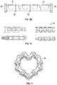
- FIG. 9A and FIG. 9B show another embodiment of the present disclosure having a roller chain adapted to engage the loading tube;
- FIG. 10 illustrates an embodiment of the roller chain engaging the loading tube, in accordance with various embodiments of the present disclosure
- FIG. 11 illustrates an embodiment of the roller chain of the present disclosure with its ends connected head to tail
- FIG. 12 shows embodiment of the present disclosure in which the longitudinal centerline of the loading tube is offset from the longitudinal centerline of the carrier
- FIG. 13 illustrates an embodiment of the present disclosure deployed in a deviated well
- FIGS. 14A-14C illustrate the angled shaped charges of the present disclosure in deviated wellbores.
- connection As used herein, the terms “connect”, “connection”, “connected”, “in connection with”, and “connecting” are used to mean “in direct connection with” or “in connection with via one or more elements”; and the term “set” is used to mean “one element” or “more than one element”. Further, the terms “couple”, “coupling”, “coupled”, “coupled together”, and “coupled with” are used to mean “directly coupled together” or “coupled together via one or more elements”. As used herein, the terms “up” and “down”; “upper” and “lower”; “top” and “bottom”; and other like terms indicating relative positions to a given point or element are utilized to more clearly describe some elements.
- references to “one embodiment” or “an embodiment” means that a particular feature or features, structures, or characteristics may be combined in any suitable manner in one or more implementations or one or more embodiments.
- FIG. 1 shows a cross section of a conventional perforating gun.
- the conventional perforating gun indicated generally as 1 , comprises a shaped charge 10 , a loading tube 12 , a gun carrier 14 , and a detonating cord 16 .
- the illustrated gun 1 also includes a scallop 18 machined out of the gun carrier 14 and aligned with the shaped charge 10 .
- the illustrated conventional perforating gun 1 is a scalloped gun 1 , it is important to note that the present disclosure is equally applicable to slick-walled guns.
- FIG. 2 illustrates an embodiment of the present disclosure of a perforating gun 1 having the shaped charges 10 mounted in a loading tube 12 that swivels within the gun carrier 14 .
- the loading tube 12 is mounted on a swivel 26 such as a radial bearing that enables the loading tube 12 to freely swivel within the gun carrier 14 .
- the shaped charges 10 In the case of scalloped perforating guns 1 , as shown in FIG. 2 , the shaped charges 10 must be oriented within the gun carrier 14 such that the shaped charges 10 are aligned with and shoot through the scallops 18 .
- the loading tube 12 swivels to the correct orientation under its own weight (which includes the weight of the shaped charges 10 ) into proper alignment with the scallops 18 .
- the center of gravity of the loading tube 12 may need to be altered through the addition of weights 20 that cause the swiveling loading tube 12 to rotate to the orientation desired (downward in FIG. 2 ).
- the weight 20 is a semi-circular weight.
- the weight 20 can be any number of types or configurations such as hollow flask type weights filled with a high-density material, or half solid metal bars, for example. All such modifications remain within the purview of the present disclosure.
- the loading tube 12 in FIG. 2 is shown mounted approximate the longitudinal centerline of the gun carrier 14 ; however, it should be understood that in alternate embodiments of the present disclosure the loading tube 12 may be mounted within the swivel 26 such that the loading tube 12 is offset from the longitudinal centerline of the gun carrier 14 . Such offset embodiments are illustrated with reference to FIG. 12 below and remain within the scope of the present disclosure.
- FIG. 3 An embodiment of the present disclosure having scallops 18 is illustrated in FIG. 3 .
- the gun carrier 14 is lowered into the well 22 by the work string 24 .
- a swivel 26 such as a radial bearing, is provided within the gun carrier 14 to enable the loading tube 12 to rotate as necessary. If needed, one or more weights may be affixed to the lower end of the carrier 14 and/or the loading tube 12 to cause the carrier 14 to rotate such that the scallops 18 , and their associated shaped charges 10 , are facing downward.
- the swivel 26 is configured to allow the free rotation of the internal loading tube 12 based on the center of gravity of the loading tube 12 .
- the center of gravity of the loading tube 12 is such that the loading tube 12 will rotate under its own weight to the proper orientation
- the addition of weights is not necessary.
- the methodology described herein is equally applicable and the shaped charges 10 are oriented in a downward direction without concern for alignment with the scallops 18 .
- the swivel 26 may comprise a satellite planetary gear mechanism 30 , such as shown in FIG. 4 .
- the planetary gear as known in the art, comprises a sun gear 50 , a planet gears 52 , and a ring gear 54 .
- the swivel 26 with the planetary gear 30 is adapted to enable rotation of the internal loading tube 12 .
- combining the swivel 26 and planetary gear 30 with a mechanical/hydraulic or electrical actuating device enables the orientation of the shaped charges 10 to be accurately controlled.
- FIG. 5 An embodiment of the present disclosure having planetary gears 30 is shown in FIG. 5 .
- a planetary gear 30 A housed within a gear box 32 A supporting one end of the loading tube 10 and a second planetary gear 30 B housed within a gear box 32 B supporting the opposite end of the loading tube 10 .
- one or more additional planetary gears 30 and gear boxes 32 can be provided as additional support at locations along the loading tube 12 between the gear boxes 32 A, 32 B.
- Providing a rotational input 34 (illustrated as an arrow) to the planetary gears 30 A, 30 B results in the loading tube 12 rotating within the gun carrier 14 to the desired orientation of the shaped charges 10 .
- the rotational input 34 can result from gravity, with or without added weights, or from a mechanical/hydraulic or electrical actuating device.
- FIG. 6 illustrates an embodiment of the present disclosure having multiple perforating guns 1 A, 1 B connected within a gun string.
- the lower perforating gun 1 B is only partially shown in FIG. 6 but has similar features to the upper perforating gun 1 A.
- the perforating guns 1 A, 1 B each having shaped charges 10 carried by a loading tube 12 housed within a gun carrier 14 .
- Gear boxes 32 A, 32 B, 32 C located at the ends of the respective perforating guns 1 A provide support for the loading tubes 12 and house the gears that allow for rotation of the loading tubes 12 within the gun carriers 14 .
- planetary gears 30 A, 30 B, 30 C are housed within the gear boxes 32 A, 32 B, 32 C, however, it should be understood that other gearing mechanisms may be used and remain within the purview of the present disclosure.
- the embodiment of the present disclosure illustrated in FIG. 6 further comprises an actuating device (i.e. transmission sub) 36 .
- the actuating device 36 is designed to transmit torque to a control rod 38 that in turn causes a torque 37 (shown as an arrow) or rotational force to be applied to the gear 30 A housed within the upper gear box 32 A. Rotation of the gear 30 A acts to rotate the entire loading tube 12 within the gun carrier 14 in the upper perforating gun 1 A. Likewise, the rotational force 37 is transmitted to the lower perforating gun 1 B, through the action of the additional gears 30 B, 30 C. In this manner, the actuating device 36 can be used to precisely control the orientation of the shaped charges 10 .
- the actuating device 36 illustrated in FIG. 6 may be disengaged such that it does not transmit forces 37 to gear 30 A and does not resist or impede rotation of gear 30 A. In this manner, the rotation of gear 30 A, and thus the loading tubes 12 , may occur naturally due to gravitational forces. In still other embodiments in which the orientation of the shaped charges is controlled naturally by gravity, it may not be necessary to provide the actuating device 36 .
- FIGS. 7A-7E illustrate an embodiment of the present disclosure comprising planetary gears 30 enabling natural, by gravity, orientation of the loading tube 12 .
- the gears 30 are self-orienting through the use of weights, such as tungsten.
- FIG. 7A shows a cross-sectional view of the internal rotating loading tube 12 housed within the gun carrier 14 .
- the loading tube 12 is rotatable through the use of planetary gears 30 A, 30 B, located at opposing ends of the loading tube 12 .
- Adapter 40 enables additional perforating guns to be carried within the gun string.
- the gun adapter 40 can be replaced by longer sealed ballstic transfer with trigger charge adapter, which fits for iron rough neck (IRN) operation without human intervention.
- IRN iron rough neck
- FIG. 7B shows a cross-sectional view of the internal rotating loading tube 12
- FIG. 7C provides a more detailed view of the loading tube 12 of FIG. 7B
- weights 42 are housed between a retainer frame 44 and a retainer plate 46 .
- the weights are sized and shaped to provide alter the center of gravity of the loading tube 12 such that it rotate to the proper orientation.
- the charges 10 shown are dummy charges with zero degree phasing.
- FIGS. 7D-7E show cross-sectional and perspective views of an embodiment of the planetary gears 30 of the embodiment of the present disclosure of FIGS. 7A-7E .
- the planetary gears 30 have a sun gear 50 , a planet gear 52 , and a ring gear 54 .
- the planetary gear 30 further comprises a loading tube support disk 56 .
- FIG. 8 illustrates an embodiment of the planetary gear 30 for use in embodiments of the present invention that further include an actuation device.
- the collar 50 a of the sun gear 50 is provided with a longer dimension such that it can be connected to, and oriented by, an actuation device (not shown), such as an electric, mechanical, or hydraulic motor.
- the actuating device controls the orientation of the loading tube 12 . In this manner, the loading tube 12 can be rotated to the appropriate orientation and maintained in the appropriate orientation by controlling the actuation device.
- FIGS. 9A and 9B show another embodiment of the present disclosure in which a roller chain 60 is used to orient the loading tube 12 carrying the shaped charges 10 .
- the roller chain 60 is connected head to tail to construct an enclosed ring.
- the roller chain 60 is wrapped around the loading tube 12 to enable rotation of the loading tube 12 and thus orientation of the shaped charges 10 .
- the roller chain 60 should be made of steel or other materials of sufficient strength to enable rotation of the loading tube 12 when engaged.
- the loading tube 12 in the illustrated embodiment of the present disclosure has bearing supports 62 at opposing ends of the loading tube 12 .
- the bearing supports 62 allow for rotation of the loading tube 12 upon action of the roller chain 60 .
- the location and spacing of the roller chains 60 is pre-selected and may be based upon the specific application.
- Each roller chain 60 may be positioned between any two (2) shaped charges 10 .
- the loading tube 12 may be designed with pre-cut bendable tabs, such that pairs of tabs with a distance between to fit a chain 60 width will be bent to constrain the axial movement of the chain 60 .
- the roller chain 60 may be an off-the-shelf product, examples of which are shown in FIG. 10 .
- the roller chain 60 may be cut to the proper length based on the outer diameter (OD) of loading tube 12 and the ends of the chain 60 can be connected head to tail as shown in FIG. 11 .
- the chain 60 should not tighten around the loading tube 12 such that it impedes rotation of the loading tube 12 . This particularly true when desiring to orient the loading tube 12 naturally under gravity.
- FIG. 12 Another embodiment of the present disclosure is shown in FIG. 12 .
- the loading tube 12 is offset from the center of the gun carrier 14 .
- the loading tube 12 is mounted on radial bearings 68 such that the longitudinal centerline 12 a of the loading tube 12 is offset from the longitudinal centerline 14 a of the gun carrier 14 .
- the offset allows the eccentric weight of the loading tube 12 to assist in orienting the shape charges 10 .
- the weight of the shaped charges 10 themselves also become orienting weights due to the offset.
- the radial bearings 68 may be disposed, at least partially, in an aperture 15 in a sidewall 13 of the loading tube 12 .
- the radial bearings 68 may be mounted on a spacer 66 .
- the spacer 66 may be an offset spacer.
- An offset mount at each end of the loading tube 12 has thrust bearings 64 that assist in reducing friction and help locate the ballistic transfer in the proper position for reliable performance.
- offset loading tube 12 shown in FIG. 12 is mounted on radial bearings 68
- the offset loading tube 12 can be mounted on planetary gears as described herein with reference to FIGS. 4-8 .
- FIG. 12 there may also be provided “puzzle cuts” 70 in the loading tube 12 that allow some articulation of the loading tube 12 , during conveyance. The articulation prevents or minimizes orientation of the shaped charges 10 to the bend direction in bent wellbore sections.
- the shaped charges 10 may be tilted or angled relative to the perpendicular of the longitudinal axis of the loading tube 12 .
- a large proportion of wells are drilled at high angle to reduce drilling complications as well as improve accessibility of the well by wireline for intervention (sand bailing/isolation). For this reason, many of these wells are drilled between 40° to 60° deviation. As shown in FIG. 13 , for perforating gun systems 1 deployed by wireline or TCP for sand prevention, even with ideal orientation, the angle of the shaped charges 10 can be over 30° from optimal, with this deviation widening if the orientation accuracy is impaired.
- FIGS. 14A-14C illustrate the angled shaped charges 10 of the present invention in a vertical well ( FIG. 14A ), a 40-degree deviated well ( FIG. 14B ) and a 60-degree deviated well ( FIG. 14C ).
- the shaped charges 10 are angled relative to the longitudinal axis of the loading tube 12 .
- the optimum angle of the shaped charges 10 can be rigidly fixed, achieved by weighting the shaped charges, oriented by an actuating device such as has been described herein, or can be oriented by conventional means.
- the optimum angle of the shaped charges 10 is based on the direction of maximum stress for the deviated wellbore 80 .
Abstract
Description
Claims (17)
Priority Applications (5)
| Application Number | Priority Date | Filing Date | Title |
|---|---|---|---|
| US16/222,095 US11414965B2 (en) | 2018-02-27 | 2018-12-17 | Rotating loading tube and angled shaped charges for oriented perforating |
| PCT/US2019/019776 WO2019168938A1 (en) | 2018-02-27 | 2019-02-27 | Rotating loading tube and angled shaped charges for oriented perforating |
| AU2019227708A AU2019227708A1 (en) | 2018-02-27 | 2019-02-27 | Rotating loading tube and angled shaped charges for oriented perforating |
| GB2013381.5A GB2584576B (en) | 2018-02-27 | 2019-02-27 | Rotating loading tube and angled shaped charges for oriented perforating |
| NO20200933A NO20200933A1 (en) | 2018-02-27 | 2020-08-27 | Rotating loading tube and angled shaped charges for oriented perforating |
Applications Claiming Priority (3)
| Application Number | Priority Date | Filing Date | Title |
|---|---|---|---|
| US201862635765P | 2018-02-27 | 2018-02-27 | |
| US201862747723P | 2018-10-19 | 2018-10-19 | |
| US16/222,095 US11414965B2 (en) | 2018-02-27 | 2018-12-17 | Rotating loading tube and angled shaped charges for oriented perforating |
Publications (2)
| Publication Number | Publication Date |
|---|---|
| US20190264548A1 US20190264548A1 (en) | 2019-08-29 |
| US11414965B2 true US11414965B2 (en) | 2022-08-16 |
Family
ID=67685612
Family Applications (1)
| Application Number | Title | Priority Date | Filing Date |
|---|---|---|---|
| US16/222,095 Active US11414965B2 (en) | 2018-02-27 | 2018-12-17 | Rotating loading tube and angled shaped charges for oriented perforating |
Country Status (5)
| Country | Link |
|---|---|
| US (1) | US11414965B2 (en) |
| AU (1) | AU2019227708A1 (en) |
| GB (1) | GB2584576B (en) |
| NO (1) | NO20200933A1 (en) |
| WO (1) | WO2019168938A1 (en) |
Families Citing this family (9)
| Publication number | Priority date | Publication date | Assignee | Title |
|---|---|---|---|---|
| US11078762B2 (en) | 2019-03-05 | 2021-08-03 | Swm International, Llc | Downhole perforating gun tube and components |
| WO2021122797A1 (en) | 2019-12-17 | 2021-06-24 | DynaEnergetics Europe GmbH | Modular perforating gun system |
| CN111411904B (en) * | 2020-01-20 | 2021-03-19 | 西南石油大学 | RFID-based underground torque clutch type well drilling resistance reducing device |
| CN111188599B (en) * | 2020-02-22 | 2020-09-01 | 大庆金祥寓科技有限公司 | Energy-releasing expansion perforation device |
| USD968474S1 (en) | 2020-04-30 | 2022-11-01 | DynaEnergetics Europe GmbH | Gun housing |
| US11512565B2 (en) | 2020-12-01 | 2022-11-29 | Halliburton Energy Services, Inc. | Plastic weight assembly for downhole perforating gun |
| US11391127B1 (en) | 2020-12-31 | 2022-07-19 | Halliburton Energy Services, Inc. | Adjustable perforating gun orientation system |
| US11732556B2 (en) | 2021-03-03 | 2023-08-22 | DynaEnergetics Europe GmbH | Orienting perforation gun assembly |
| US11761312B2 (en) * | 2021-07-09 | 2023-09-19 | Schlumberger Technology Corporation | Modular perforation tool |
Citations (50)
| Publication number | Priority date | Publication date | Assignee | Title |
|---|---|---|---|---|
| US1987316A (en) | 1933-09-07 | 1935-01-08 | Zimmer Edward | Yieldable drive shaft |
| US2500359A (en) | 1947-07-26 | 1950-03-14 | Wright Aeronautical Corp | Shaft seal |
| US3014542A (en) | 1959-12-01 | 1961-12-26 | Jersey Production Res Corp | Turbo-type earth drill |
| US3089416A (en) | 1959-10-05 | 1963-05-14 | Gilbert Bruce | Methods of and means for fracturing earth formations |
| US3145787A (en) | 1961-12-21 | 1964-08-25 | Jersey Prod Res Co | Rotary and input drilling apparatus |
| US4153118A (en) | 1977-03-28 | 1979-05-08 | Hart Michael L | Method of and apparatus for perforating boreholes |
| US4410051A (en) | 1981-02-27 | 1983-10-18 | Dresser Industries, Inc. | System and apparatus for orienting a well casing perforating gun |
| US4438810A (en) | 1981-10-26 | 1984-03-27 | Dresser Industries, Inc. | Apparatus for decentralizing and orienting a well logging or perforating instrument |
| GB2128719A (en) | 1982-10-20 | 1984-05-02 | Vann Inc Geo | Gravity oriented perforating gun for use in slanted boreholes |
| US4523649A (en) | 1983-05-25 | 1985-06-18 | Baker Oil Tools, Inc. | Rotational alignment method and apparatus for tubing conveyed perforating guns |
| US4613002A (en) | 1984-04-30 | 1986-09-23 | Hughes Tool Company | Downhole drilling tool with improved swivel |
| US4919205A (en) * | 1989-11-27 | 1990-04-24 | Dollison William W | Friction-reducing device |
| US5010964A (en) | 1990-04-06 | 1991-04-30 | Atlantic Richfield Company | Method and apparatus for orienting wellbore perforations |
| US5040619A (en) | 1990-04-12 | 1991-08-20 | Halliburton Logging Services, Inc. | Wireline supported perforating gun enabling oriented perforations |
| US5163721A (en) | 1990-10-24 | 1992-11-17 | Cajon Company | Fluid coupling with gasket retainer having interlocking portions |
| US5176406A (en) | 1990-12-20 | 1993-01-05 | Straghan Robert G | Coupling |
| US5211714A (en) | 1990-04-12 | 1993-05-18 | Halliburton Logging Services, Inc. | Wireline supported perforating gun enabling oriented perforations |
| US5259466A (en) | 1992-06-11 | 1993-11-09 | Halliburton Company | Method and apparatus for orienting a perforating string |
| US5273121A (en) | 1992-04-03 | 1993-12-28 | Eastern Oil Tools Pte Ltd. | Intercarrier mechanism for connecting and orienting tubing conveyed perforating guns |
| US5285683A (en) | 1992-10-01 | 1994-02-15 | Halliburton Company | Method and apparatus for determining orientation of a wellbore relative to formation stress fields |
| US5318123A (en) | 1992-06-11 | 1994-06-07 | Halliburton Company | Method for optimizing hydraulic fracturing through control of perforation orientation |
| US5335724A (en) | 1993-07-28 | 1994-08-09 | Halliburton Company | Directionally oriented slotting method |
| US5366014A (en) | 1993-11-04 | 1994-11-22 | Halliburton Company | Method and apparatus for perforating a well using a modular perforating gun system |
| US5394941A (en) | 1993-06-21 | 1995-03-07 | Halliburton Company | Fracture oriented completion tool system |
| RU2059806C1 (en) | 1991-11-11 | 1996-05-10 | Сергей Петрович Антипинский | Well jet perforator |
| US5603379A (en) | 1994-08-31 | 1997-02-18 | Halliburton Company | Bi-directional explosive transfer apparatus and method |
| RU2112877C1 (en) | 1996-07-18 | 1998-06-10 | Томский политехнический университет | Combined geophysical instrument |
| US5778979A (en) | 1996-08-16 | 1998-07-14 | Burleson; John D. | Latch and release perforating gun connector and method |
| GB2329659A (en) | 1996-12-04 | 1999-03-31 | Schlumberger Ltd | Casing perforator orientated with eccentric weight and swivel means |
| US5964294A (en) | 1996-12-04 | 1999-10-12 | Schlumberger Technology Corporation | Apparatus and method for orienting a downhole tool in a horizontal or deviated well |
| US6003599A (en) | 1997-09-15 | 1999-12-21 | Schlumberger Technology Corporation | Azimuth-oriented perforating system and method |
| WO2000075485A1 (en) | 1999-06-09 | 2000-12-14 | Schlumberger Holdings Limited | Method and system for oriented perforating in a well with permanent sensors |
| US6173773B1 (en) | 1999-04-15 | 2001-01-16 | Schlumberger Technology Corporation | Orienting downhole tools |
| US6230825B1 (en) | 1998-07-29 | 2001-05-15 | James T. Aumann | Apparatus for recovering core samples under pressure |
| GB2363449A (en) | 1999-01-13 | 2001-12-19 | Schlumberger Technology Corp | Method and apparatus for coupling explosive devices |
| RU2179235C1 (en) | 2001-03-05 | 2002-02-10 | Общество с ограниченной ответственностью "Научно-производственная компания "ВНИИЭФ-Спецгеосервис" | Device for combined well perforation and formation fracturing |
| GB2374887A (en) | 2001-04-27 | 2002-10-30 | Schlumberger Holdings | Orienting perforating guns and confirming their orientation upon firing |
| US20030098158A1 (en) * | 2001-11-28 | 2003-05-29 | George Flint R. | Internally oriented perforating apparatus |
| US6591911B1 (en) | 1999-07-22 | 2003-07-15 | Schlumberger Technology Corporation | Multi-directional gun carrier method and apparatus |
| US20030188867A1 (en) * | 2001-04-27 | 2003-10-09 | Parrott Robert A. | Method and apparatus for orienting perforating devices |
| US6679327B2 (en) | 2001-11-30 | 2004-01-20 | Baker Hughes, Inc. | Internal oriented perforating system and method |
| US20050092493A1 (en) | 2003-10-29 | 2005-05-05 | Sukup Richard A. | Engineered solution for controlled buoyancy perforating |
| US7013977B2 (en) | 2003-06-11 | 2006-03-21 | Halliburton Energy Services, Inc. | Sealed connectors for automatic gun handling |
| US20070175637A1 (en) | 2006-02-01 | 2007-08-02 | Leising Lawrence J | System and method for forming cavities in a well |
| US20090242198A1 (en) * | 2008-03-26 | 2009-10-01 | Baker Hughes Incorporated | Selectively Angled Perforating |
| US8002035B2 (en) | 2009-03-13 | 2011-08-23 | Halliburton Energy Services, Inc. | System and method for dynamically adjusting the center of gravity of a perforating apparatus |
| US8181718B2 (en) | 2007-12-17 | 2012-05-22 | Halliburton Energy Services, Inc. | Perforating gun gravitational orientation system |
| US8443886B2 (en) | 2010-08-12 | 2013-05-21 | CCS Leasing and Rental, LLC | Perforating gun with rotatable charge tube |
| US20150226044A1 (en) * | 2014-02-12 | 2015-08-13 | Owen Oil Tools Lp | Perforating gun with eccentric rotatable charge tube |
| US20160047205A1 (en) * | 2013-11-15 | 2016-02-18 | COREteQ Systems Ltd. | Electric actuator |
-
2018
- 2018-12-17 US US16/222,095 patent/US11414965B2/en active Active
-
2019
- 2019-02-27 GB GB2013381.5A patent/GB2584576B/en active Active
- 2019-02-27 AU AU2019227708A patent/AU2019227708A1/en active Pending
- 2019-02-27 WO PCT/US2019/019776 patent/WO2019168938A1/en active Application Filing
-
2020
- 2020-08-27 NO NO20200933A patent/NO20200933A1/en unknown
Patent Citations (58)
| Publication number | Priority date | Publication date | Assignee | Title |
|---|---|---|---|---|
| US1987316A (en) | 1933-09-07 | 1935-01-08 | Zimmer Edward | Yieldable drive shaft |
| US2500359A (en) | 1947-07-26 | 1950-03-14 | Wright Aeronautical Corp | Shaft seal |
| US3089416A (en) | 1959-10-05 | 1963-05-14 | Gilbert Bruce | Methods of and means for fracturing earth formations |
| US3014542A (en) | 1959-12-01 | 1961-12-26 | Jersey Production Res Corp | Turbo-type earth drill |
| US3145787A (en) | 1961-12-21 | 1964-08-25 | Jersey Prod Res Co | Rotary and input drilling apparatus |
| US4153118A (en) | 1977-03-28 | 1979-05-08 | Hart Michael L | Method of and apparatus for perforating boreholes |
| US4410051A (en) | 1981-02-27 | 1983-10-18 | Dresser Industries, Inc. | System and apparatus for orienting a well casing perforating gun |
| US4438810A (en) | 1981-10-26 | 1984-03-27 | Dresser Industries, Inc. | Apparatus for decentralizing and orienting a well logging or perforating instrument |
| GB2128719A (en) | 1982-10-20 | 1984-05-02 | Vann Inc Geo | Gravity oriented perforating gun for use in slanted boreholes |
| US4637478A (en) | 1982-10-20 | 1987-01-20 | Halliburton Company | Gravity oriented perforating gun for use in slanted boreholes |
| US4523649A (en) | 1983-05-25 | 1985-06-18 | Baker Oil Tools, Inc. | Rotational alignment method and apparatus for tubing conveyed perforating guns |
| US4613002A (en) | 1984-04-30 | 1986-09-23 | Hughes Tool Company | Downhole drilling tool with improved swivel |
| US4919205A (en) * | 1989-11-27 | 1990-04-24 | Dollison William W | Friction-reducing device |
| US5010964A (en) | 1990-04-06 | 1991-04-30 | Atlantic Richfield Company | Method and apparatus for orienting wellbore perforations |
| US5040619A (en) | 1990-04-12 | 1991-08-20 | Halliburton Logging Services, Inc. | Wireline supported perforating gun enabling oriented perforations |
| US5211714A (en) | 1990-04-12 | 1993-05-18 | Halliburton Logging Services, Inc. | Wireline supported perforating gun enabling oriented perforations |
| EP0452126A2 (en) | 1990-04-12 | 1991-10-16 | Halliburton Company | Apparatus for orienting perforating gun |
| US5163721A (en) | 1990-10-24 | 1992-11-17 | Cajon Company | Fluid coupling with gasket retainer having interlocking portions |
| US5176406A (en) | 1990-12-20 | 1993-01-05 | Straghan Robert G | Coupling |
| RU2059806C1 (en) | 1991-11-11 | 1996-05-10 | Сергей Петрович Антипинский | Well jet perforator |
| US5273121A (en) | 1992-04-03 | 1993-12-28 | Eastern Oil Tools Pte Ltd. | Intercarrier mechanism for connecting and orienting tubing conveyed perforating guns |
| US5259466A (en) | 1992-06-11 | 1993-11-09 | Halliburton Company | Method and apparatus for orienting a perforating string |
| US5318123A (en) | 1992-06-11 | 1994-06-07 | Halliburton Company | Method for optimizing hydraulic fracturing through control of perforation orientation |
| US5285683A (en) | 1992-10-01 | 1994-02-15 | Halliburton Company | Method and apparatus for determining orientation of a wellbore relative to formation stress fields |
| US5394941A (en) | 1993-06-21 | 1995-03-07 | Halliburton Company | Fracture oriented completion tool system |
| US5335724A (en) | 1993-07-28 | 1994-08-09 | Halliburton Company | Directionally oriented slotting method |
| US5366014A (en) | 1993-11-04 | 1994-11-22 | Halliburton Company | Method and apparatus for perforating a well using a modular perforating gun system |
| US5603379A (en) | 1994-08-31 | 1997-02-18 | Halliburton Company | Bi-directional explosive transfer apparatus and method |
| RU2112877C1 (en) | 1996-07-18 | 1998-06-10 | Томский политехнический университет | Combined geophysical instrument |
| US5778979A (en) | 1996-08-16 | 1998-07-14 | Burleson; John D. | Latch and release perforating gun connector and method |
| GB2329659A (en) | 1996-12-04 | 1999-03-31 | Schlumberger Ltd | Casing perforator orientated with eccentric weight and swivel means |
| US5964294A (en) | 1996-12-04 | 1999-10-12 | Schlumberger Technology Corporation | Apparatus and method for orienting a downhole tool in a horizontal or deviated well |
| US6003599A (en) | 1997-09-15 | 1999-12-21 | Schlumberger Technology Corporation | Azimuth-oriented perforating system and method |
| US6230825B1 (en) | 1998-07-29 | 2001-05-15 | James T. Aumann | Apparatus for recovering core samples under pressure |
| GB2363449A (en) | 1999-01-13 | 2001-12-19 | Schlumberger Technology Corp | Method and apparatus for coupling explosive devices |
| US6173773B1 (en) | 1999-04-15 | 2001-01-16 | Schlumberger Technology Corporation | Orienting downhole tools |
| WO2000075485A1 (en) | 1999-06-09 | 2000-12-14 | Schlumberger Holdings Limited | Method and system for oriented perforating in a well with permanent sensors |
| US6378607B1 (en) | 1999-06-09 | 2002-04-30 | Schlumberger Technology Corporation | Method and system for oriented perforating in a well with permanent sensors |
| US6591911B1 (en) | 1999-07-22 | 2003-07-15 | Schlumberger Technology Corporation | Multi-directional gun carrier method and apparatus |
| RU2179235C1 (en) | 2001-03-05 | 2002-02-10 | Общество с ограниченной ответственностью "Научно-производственная компания "ВНИИЭФ-Спецгеосервис" | Device for combined well perforation and formation fracturing |
| US20030188867A1 (en) * | 2001-04-27 | 2003-10-09 | Parrott Robert A. | Method and apparatus for orienting perforating devices |
| US8439114B2 (en) | 2001-04-27 | 2013-05-14 | Schlumberger Technology Corporation | Method and apparatus for orienting perforating devices |
| GB2374887A (en) | 2001-04-27 | 2002-10-30 | Schlumberger Holdings | Orienting perforating guns and confirming their orientation upon firing |
| US7000699B2 (en) | 2001-04-27 | 2006-02-21 | Schlumberger Technology Corporation | Method and apparatus for orienting perforating devices and confirming their orientation |
| US7114564B2 (en) | 2001-04-27 | 2006-10-03 | Schlumberger Technology Corporation | Method and apparatus for orienting perforating devices |
| US6595290B2 (en) | 2001-11-28 | 2003-07-22 | Halliburton Energy Services, Inc. | Internally oriented perforating apparatus |
| US20030098158A1 (en) * | 2001-11-28 | 2003-05-29 | George Flint R. | Internally oriented perforating apparatus |
| US6679327B2 (en) | 2001-11-30 | 2004-01-20 | Baker Hughes, Inc. | Internal oriented perforating system and method |
| US7013977B2 (en) | 2003-06-11 | 2006-03-21 | Halliburton Energy Services, Inc. | Sealed connectors for automatic gun handling |
| US20050092493A1 (en) | 2003-10-29 | 2005-05-05 | Sukup Richard A. | Engineered solution for controlled buoyancy perforating |
| US20070175637A1 (en) | 2006-02-01 | 2007-08-02 | Leising Lawrence J | System and method for forming cavities in a well |
| US8181718B2 (en) | 2007-12-17 | 2012-05-22 | Halliburton Energy Services, Inc. | Perforating gun gravitational orientation system |
| US20090242198A1 (en) * | 2008-03-26 | 2009-10-01 | Baker Hughes Incorporated | Selectively Angled Perforating |
| US8002035B2 (en) | 2009-03-13 | 2011-08-23 | Halliburton Energy Services, Inc. | System and method for dynamically adjusting the center of gravity of a perforating apparatus |
| US8066083B2 (en) | 2009-03-13 | 2011-11-29 | Halliburton Energy Services, Inc. | System and method for dynamically adjusting the center of gravity of a perforating apparatus |
| US8443886B2 (en) | 2010-08-12 | 2013-05-21 | CCS Leasing and Rental, LLC | Perforating gun with rotatable charge tube |
| US20160047205A1 (en) * | 2013-11-15 | 2016-02-18 | COREteQ Systems Ltd. | Electric actuator |
| US20150226044A1 (en) * | 2014-02-12 | 2015-08-13 | Owen Oil Tools Lp | Perforating gun with eccentric rotatable charge tube |
Non-Patent Citations (3)
| Title |
|---|
| Exam Report Under Section 18(3) issued in United Kingdom patent Application GB2013381.5 dated Nov. 29, 2021, 4 pages. |
| International Preliminary Report on Patentability issued in the related PCT Application PCT/US2019/019776, dated Sep. 3, 2020 (8 pages). |
| International Search Report and Written Opinion issued in the related PCT Application PCT/US2019/019776, dated Jun. 7, 2019 (12 pages). |
Also Published As
| Publication number | Publication date |
|---|---|
| WO2019168938A1 (en) | 2019-09-06 |
| GB2584576B (en) | 2022-04-20 |
| GB2584576A (en) | 2020-12-09 |
| NO20200933A1 (en) | 2020-08-27 |
| GB202013381D0 (en) | 2020-10-07 |
| AU2019227708A1 (en) | 2020-09-17 |
| US20190264548A1 (en) | 2019-08-29 |
Similar Documents
| Publication | Publication Date | Title |
|---|---|---|
| US11414965B2 (en) | Rotating loading tube and angled shaped charges for oriented perforating | |
| EP2406459B1 (en) | System and method for dynamically adjusting the center of gravity of a perforating apparatus | |
| EP3105413B1 (en) | Perforating gun with eccentric rotatable charge tube | |
| US7621342B2 (en) | Method for retaining debris in a perforating apparatus | |
| EP3380700B1 (en) | Perforating gun system and method | |
| US7360587B2 (en) | Debris reduction perforating apparatus | |
| US10851624B2 (en) | Perforating gun assembly and methods of use | |
| US20220074289A1 (en) | Oilfield perforating self-positioning systems and methods | |
| US20100163238A1 (en) | Method and apparatus for perforating with reduced debris in wellbore | |
| US20060102352A1 (en) | Debris reduction perforating apparatus and method for use of same | |
| CA3004273A1 (en) | Perforating gun system and method | |
| WO2022265672A1 (en) | Method and apparatus for shaped charge orientation |
Legal Events
| Date | Code | Title | Description |
|---|---|---|---|
| FEPP | Fee payment procedure |
Free format text: ENTITY STATUS SET TO UNDISCOUNTED (ORIGINAL EVENT CODE: BIG.); ENTITY STATUS OF PATENT OWNER: LARGE ENTITY |
|
| STPP | Information on status: patent application and granting procedure in general |
Free format text: DOCKETED NEW CASE - READY FOR EXAMINATION |
|
| AS | Assignment |
Owner name: SCHLUMBERGER TECHNOLOGY CORPORATION, TEXAS Free format text: ASSIGNMENT OF ASSIGNORS INTEREST;ASSIGNORS:ZHAO, HAIFENG;MEDINA PACHECO, LUIS RODOLFO;GILL, BENNIE;AND OTHERS;SIGNING DATES FROM 20190610 TO 20190827;REEL/FRAME:050954/0313 |
|
| STPP | Information on status: patent application and granting procedure in general |
Free format text: NON FINAL ACTION MAILED |
|
| STPP | Information on status: patent application and granting procedure in general |
Free format text: FINAL REJECTION MAILED |
|
| STPP | Information on status: patent application and granting procedure in general |
Free format text: DOCKETED NEW CASE - READY FOR EXAMINATION |
|
| STPP | Information on status: patent application and granting procedure in general |
Free format text: NON FINAL ACTION MAILED |
|
| STPP | Information on status: patent application and granting procedure in general |
Free format text: RESPONSE TO NON-FINAL OFFICE ACTION ENTERED AND FORWARDED TO EXAMINER |
|
| STPP | Information on status: patent application and granting procedure in general |
Free format text: NOTICE OF ALLOWANCE MAILED -- APPLICATION RECEIVED IN OFFICE OF PUBLICATIONS |
|
| STPP | Information on status: patent application and granting procedure in general |
Free format text: PUBLICATIONS -- ISSUE FEE PAYMENT VERIFIED |
|
| STCF | Information on status: patent grant |
Free format text: PATENTED CASE |