EP1448864B1 - Holding element und use of such a holding element - Google Patents
Holding element und use of such a holding element Download PDFInfo
- Publication number
- EP1448864B1 EP1448864B1 EP02776800A EP02776800A EP1448864B1 EP 1448864 B1 EP1448864 B1 EP 1448864B1 EP 02776800 A EP02776800 A EP 02776800A EP 02776800 A EP02776800 A EP 02776800A EP 1448864 B1 EP1448864 B1 EP 1448864B1
- Authority
- EP
- European Patent Office
- Prior art keywords
- holding element
- specified
- profile
- holding
- cross
- Prior art date
- Legal status (The legal status is an assumption and is not a legal conclusion. Google has not performed a legal analysis and makes no representation as to the accuracy of the status listed.)
- Expired - Lifetime
Links
Images


Classifications
-
- E—FIXED CONSTRUCTIONS
- E06—DOORS, WINDOWS, SHUTTERS, OR ROLLER BLINDS IN GENERAL; LADDERS
- E06B—FIXED OR MOVABLE CLOSURES FOR OPENINGS IN BUILDINGS, VEHICLES, FENCES OR LIKE ENCLOSURES IN GENERAL, e.g. DOORS, WINDOWS, BLINDS, GATES
- E06B1/00—Border constructions of openings in walls, floors, or ceilings; Frames to be rigidly mounted in such openings
- E06B1/56—Fastening frames to the border of openings or to similar contiguous frames
- E06B1/60—Fastening frames to the border of openings or to similar contiguous frames by mechanical means, e.g. anchoring means
- E06B1/6007—Fastening frames to the border of openings or to similar contiguous frames by mechanical means, e.g. anchoring means between similar contiguous frames
-
- E—FIXED CONSTRUCTIONS
- E04—BUILDING
- E04D—ROOF COVERINGS; SKY-LIGHTS; GUTTERS; ROOF-WORKING TOOLS
- E04D3/00—Roof covering by making use of flat or curved slabs or stiff sheets
- E04D3/02—Roof covering by making use of flat or curved slabs or stiff sheets of plane slabs, slates, or sheets, or in which the cross-section is unimportant
- E04D3/06—Roof covering by making use of flat or curved slabs or stiff sheets of plane slabs, slates, or sheets, or in which the cross-section is unimportant of glass or other translucent material; Fixing means therefor
- E04D3/08—Roof covering by making use of flat or curved slabs or stiff sheets of plane slabs, slates, or sheets, or in which the cross-section is unimportant of glass or other translucent material; Fixing means therefor with metal glazing bars
- E04D2003/0818—Roof covering by making use of flat or curved slabs or stiff sheets of plane slabs, slates, or sheets, or in which the cross-section is unimportant of glass or other translucent material; Fixing means therefor with metal glazing bars the supporting section of the glazing bar consisting of several parts, e.g. compound sections
- E04D2003/0837—Sections comprising intermediate parts of insulating material
-
- E—FIXED CONSTRUCTIONS
- E06—DOORS, WINDOWS, SHUTTERS, OR ROLLER BLINDS IN GENERAL; LADDERS
- E06B—FIXED OR MOVABLE CLOSURES FOR OPENINGS IN BUILDINGS, VEHICLES, FENCES OR LIKE ENCLOSURES IN GENERAL, e.g. DOORS, WINDOWS, BLINDS, GATES
- E06B3/00—Window sashes, door leaves, or like elements for closing wall or like openings; Layout of fixed or moving closures, e.g. windows in wall or like openings; Features of rigidly-mounted outer frames relating to the mounting of wing frames
- E06B3/04—Wing frames not characterised by the manner of movement
- E06B3/263—Frames with special provision for insulation
- E06B2003/26392—Glazing bars
Definitions
- the invention relates to a holding element with a plurality of bodies, in particular for receiving components such as window frames, facade elements or the like, in which at least one of the body has an extrusion element, and two bodies are thermally separated by an insulator, wherein the extruded element consists of an aluminum alloy and the steel material serves as a reinforcement of the extruded element, as well as a use of such holding elements.
- Retainers with multiple bodies are well known in the art. They serve, for example, to separate a cold area from a warm area, so that in particular a carrier arranged between the two areas reduces heat transfer from the hot area to the cold area via the carrier arranged therebetween. In this case, for example, two carriers are thermally separated from one another by an insulator and connected to one another on the other hand.
- the stabilizing carrier are made of a metal sheet folded into a carrier.
- the sheet may be folded in regions of the carrier twice or more than one above the other.
- the known holding elements reduce the heat transfer from a warm area to a cold area very well.
- they have the disadvantage that they are disadvantageous due to their designed on a sheet metal carrier, especially in the inclusion of other components.
- the sheet-formed carriers are not particularly well suited to accommodate heavier loads, particularly by the attachment of other brackets. Especially at the transition region where a support is attached to an insulator, it may be due to limited strength Of folded from a sheet carrier or a lack of carrier volume often come to an insufficiently stable connection.
- Generic retaining elements are from the WO 99/50511 A and the DE 92 07 578 U known.
- the object of the invention is to further develop such holding elements, so that, inter alia, improves the connection between a carrier and an insulator and in particular thereby the holding element for receiving further brackets, where larger loads can be arranged, is better suited.
- the object is achieved on the one hand by a generic holding element with a material structure in which the material steel is more widely spaced from a cross-sectional inner layer of the holding element is removed as the material aluminum.
- the bodies when larger loads act on the thermally separated bodies of the holding element, it is advantageous for the bodies to consist in particular of an interface to an insulator arranged on them of an extruded element.
- the extrusion element is much better suited to make a more intimate connection to the insulator, so that larger forces between the bodies can easily be transmitted by means of the insulator arranged on them.
- the body can be made by a machining process. Particularly simple and inexpensive, it is, however, if the body according to the invention comprises an extrusion element.
- An extrusion element for example, can be produced outstandingly as a piece by the meter in an extrusion process and is thus particularly advantageous for producing and obstructing.
- the extruded element is structurally particularly easy to make if one of the body consists of a solid material.
- the aluminum alloy has a sufficiently strong structure and is relatively light compared to other metals, which in particular favors the use in facade construction.
- the cross-section of the body is reduced by material recesses. This can be done for example by appropriate holes or corresponding punched out.
- the material recesses may preferably be arranged in areas in which the power flow or the internal stresses are low. For example, for this purpose, the recesses are arranged in the region of the neutral fiber.
- the body has at least one channel extending in the longitudinal direction of the body.
- This channel allows to attach at the body end transverse to this another element such as a cross member.
- this channel can be used as a screw, for example, to attach a component by means of a corresponding screw on the body.
- a cover profile provided with a mandrel by simply pressing the dome into the channel on the body.
- the channel extending in the longitudinal direction of the body is widened to the channel inside.
- this can be between the body and a further profile element a positive connection in a simple manner can be produced.
- At least one body has a positive connection to a thermally isolating the body insulator.
- the insulator comprises a web with corresponding lugs, the insulator can be easily pressed into the channel with the enlarged channel inside to make a high-strength positive connection between the insulator and the body.
- the insulator may also have a channel extending in the longitudinal direction, which then possibly widens to the channel inside.
- At least one body has at least one profile holding web extending in the longitudinal direction of the body.
- the profile holding web can be used to advantageously accommodate further components.
- the other components are attached by a screw or a rivet to the profile holding web of the body.
- one of the body has at least one preferably in the component level projecting component holding web, with the components cooperates.
- a preferred embodiment provides that the component web and a profile holding web of the holding element are arranged at right angles to each other. hereby Among other things, the body of the holding element with their component holding webs can be easily arranged on a component.
- the holding element in particular a profile holding web of at least one body, has at least one bore for receiving a profile element.
- various material recesses may also be present on the profile-holding web of the body for receiving a further profile element, for example a cover profile, such as a cap.
- the material recesses are pre-punched or pre-drilled.
- the profile element has a steel profile.
- the body is made of a solid material, now also solid, heavier parts such as steel profiles can now attach to the holding element without this negative effects on the absorption capacity of the other profile element are to be feared at the holding element.
- the profile element can be designed structurally particularly simple and thus advantageous if the profile element is composed of at least two profile part halves and the profile part halves are preferably made of a sheet folded at least once.
- profile part halves by means of a bolt connection and / or by means of a cap or a Cap extension are connected.
- a preferred bolt connection is for example a screw connection, so that the profile part halves are releasably connected to one another.
- the cap or the cap extension can accommodate the profile part halves so that they clamp the profile part halves against each other and hold.
- a further embodiment provides that the cap relative to the cap extension has a positive connection and / or a frictional connection.
- This connection makes it possible, inter alia, to cover profile elements projecting particularly far from the holding element, for example by means of a cap provided with an extension.
- a standardized cap can optionally be adapted by a corresponding cap extension to the respective profile element conditions.
- the cap or another covering profile on the profile element in a simple embodiment, it is advantageous if at least two profile part halves in the longitudinal direction of the profile element form a preferably extended to the channel inside channel.
- At least one holding device of a cap can be arranged in the channel. This is, for example, a thorn of the cap.
- the profile elements have a holding region deviating from the channel.
- a cap or other cover profile not from the previously described channel is to be included or can, thereby a cap can be particularly easily attached to the holding portion of the profile element.
- At least one profile half has a reduced cross-section, wherein the reduced cross-section is preferably arranged between two spaced retaining regions of two profile elements.
- At least one of the thermally separated bodies is longer in the longitudinal direction than an insulator arranged thereon.
- the holding element has less material volume between the two thermally separated bodies, so that, for example, the thermal conductivity is reduced from a warm area to a cold area due to the smaller volume of material.
- such a construction is material-saving. This can be of economic importance, in particular with a high production output.
- the insulator is made of a polyamide.
- the holding element has a component, preferably two components, on which the body is arranged as a reinforcement.
- a component is part of a window frame.
- window frames are extruded from a plastic to a hollow chamber profile, which can be reinforced by a metal body.
- the retaining element has a varying rigidity in the direction of its maximum cross-sectional extension. This makes it possible to produce the holding element of different materials, so that the holding element can be made very flexible depending on the case of application.
- the holding element in the direction of its maximum cross-sectional extension has a changing modulus of elasticity.
- the holding element has a modulus of elasticity which decreases from a cross-sectional outer layer to a cross-sectional inner layer.
- the retaining element at least partially receives a very rigid and solid outer region, wherein the retaining element towards the core has a lower rigidity and thus is very elastic.
- the holding element has a material sequence which comprises the following materials from a cross-sectional outer layer to a cross-sectional inner layer: steel, aluminum, plastic.
- cross-sectional outer layer is understood in the context of the invention, an area having a maximum distance from the central position of the holding element. If the holding element is designed asymmetrically, the middle position of the holding element falls within the meaning of the invention with the central axis of the insulator of the holding element together.
- cross-sectional inner layer means an area in the vicinity of the central position of the retaining element. If the holding element is designed asymmetrically, the middle position of the holding element falls within the meaning of the invention with the central axis of the insulator of the holding element together.
- one of the bodies is provided with material recesses which, on the one hand, can reduce the thermal conductivity of the body and, on the other hand, make it possible to easily and simply arrange further components to the body and thus, for example, to a high-strength hollow chamber profile.
- the invention is achieved by a use of a retaining element described above for receiving profile elements, in particular also of facade elements or the like.
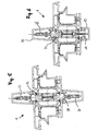
- FIGS. 1 to 11 In each case, a holding element 1 is shown in different embodiments, in which the same components of the holding element 1 are provided with the same reference numerals.
- the holding element 1 essentially comprises two thermally separated bodies 2 and 3 and an insulator 4 arranged between these two bodies 2 and 3.
- the insulator 4 has a bone-like shape with respect to its cross-section, with its two thickened side regions 5 and 6 in each case a running in the longitudinal direction of the body 2 and 3 channel 7 and 8 is arranged.
- the two channels 7 and 8 are widened with respect to their inner side, so that the side regions 5 and 6 are respectively arranged in the channel 7 and in the channel 8 and thus in each case a FonnMedic between the bodies 2 and 3 relative to the insulator 4 is formed.
- the bodies 2 and 3 each have a further channel 9 and 10 along their longitudinal extent.
- the channels 9 and 10 each have a mandrel 11 and 12 of a cover 13 and 14 respectively.
- the mandrel 11 or 12 is of the shape that it has in each case with the channel 9 and 10 a positive connection.
- channel 9 or 10 and the mandrel 11 or 12 cooperate with each other such that only a non-positive connection between the channel 9 and the mandrel 11 or the channel 10 and the mandrel 12 can be present.
- the holding element 1 comprises two components 15 and 16, wherein the cover profiles 13 and 14 form a kind of screen for bridging the spaced-apart components 15 and 16 form.
- the bodies 2 and 3 each have two component holding webs 2A, 2B, 3A and 3B.
- the Bauteilhaltestege 2A, 2B, 3A and 3B are mounted for this purpose in corresponding grooves of the components 15 and 16.
- the holding element 1 may alternatively also have a body 17 deviating from the bodies 2 and 3.
- the body 17 has a channel 18 which has a substantially greater depth than the previously mentioned channels 9 and 10. This makes it possible, the Body 17 stable form.
- An altered cover profile 19 is attached to the retaining element 1 by means of a stronger dome 20.
- the holding element 1 has a second body 21 identical to the first body 17.
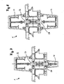
- the holding element 1 comprises a body 23, which instead of a channel 9, 10 or 18 for receiving a dome 11, 12 or 20 or in addition to a profile holding web 24 has.
- the profile holding web 24 in this case has a bore 25 in which a screw 26 is arranged, which secures the steel profile 22 to the holding element 1.
- the steel profile 22 consists of two profile part halves 22A and 22B. These two profile part halves 22A and 22B are arranged by means of the screw 26 on the profile holding web 24, thereby forming the steel profile 22 an inwardly narrowing channel 22C.
- holding element 1 for receiving two steel profiles 22 and 27 may comprise two identical bodies 23 and 28.
- the holding element 1 comprises in a further embodiment ( FIG. 6 ) a body 23 and a body 17, so that it is possible to attach a cover 29 by means of the steel profile 22 indirectly to the body 23 and a cover 19 directly to the body 17 of the holding element 1.
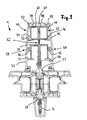
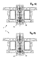
- FIGS. 7 to 11 each show a varied holding element 1 with thermally separated bodies 23 and 28. At these alternatively a plurality of partially different steel profiles 29 to 42 are arranged.
- the steel profiles 29, 31, 32 and 34 to 42 each have a holding region 43 (here only by way of example in FIG. 9 numbered) on which a cover profile is arranged in the form of a cap 44.
- the cap 44 in turn has a plurality of retaining lugs 45 to 52, with which the cap 44 is disposed on the respective holding portion 43 of a steel profile 29, 31, 32 and 34 to 42.
- a cap extension 53 is likewise arranged on the steel profile 34 via retaining lugs 54, 55, 56 and 57.
- the cap 44 and the cap extension 53 are connected to one another in a form-fitting manner by means of two plug connections 58 and 59.
- a steel profile 35 only represents the lowest possible cold or thermal bridge, for example, the profile part halves 60 and 61 of the steel profile 35 in a region 62 each have a cross-sectional reduction.
- the cross-sectional reduction can be provided depending on the embodiment in other areas of a steel section 29, 31, 32 and 34 to 42.
- the steel profile 36 is arranged in a channel 63 of the steel profile 37.
- the channel 63 is formed by the two profile part halves 64 and 65 of the steel profile 37.
- the holding element 1 ( FIG. 11 ) has a cross-sectional outer layer 82 and a cross-sectional inner layer 83 and has a maximum cross-sectional extension 84.
- a holding element 1 wherein at least one body 66 to 71 is made of a plastic, wherein the body 66 to 71, among other things, also the function of a previously described Isolator 4 takes over.
- the body 66 to 71 is designed such that it can accommodate a cover profile 13 and a steel profile 27 or a steel profile 32 on the one hand.
- the body 66 to 71 represent a much worse cold bridge than the aluminum body of the FIGS. 1 to 11 ,
- the holding elements (1) from the FIGS. 12 and 13 each show an embodiment in which a holding element (1) consists of materials such as aluminum and / or plastic.
- the holding element off FIG. 14 On the other hand, it consists of a sequence of material components "plastic, aluminum and steel”.
- the retaining elements from the FIGS. 15 to 17 each have a sequence of material components with the material components steel, plastic, aluminum, steel.
- the holding element off FIG. 18 essentially consists of only a single body 72.
- the body 72 is made of plastic in this embodiment and therefore provides overall excellent insulator properties.
- FIGS. 19 to 21 in each case a holding element 1 is shown, which only has a body 73 to 75, which is made of plastic. As a result, the bodies 73, 74 and 75 have excellent insulation properties.
- profile elements 76 to 81 are arranged.
- a plastic is particularly suitable for their production, since a plastic represents a conceivable bad cold bridge between a hot area and a cold area.
- the invention proposes a holding element with a plurality of bodies, in particular for receiving components such as window frames, facade elements or the like, in which at least one of the bodies has an extrusion element.
Abstract
Description
Die Erfindung betrifft ein Halteelement mit mehreren Körpern, insbesondere zum Aufnehmen von Bauteilen wie Fensterrahmen, Fassadenelemente oder dergleichen, bei welchem wenigstens einer der Körper ein Strangpress-Element aufweist, und zwei Körper durch einen Isolator thermisch getrennt sind, wobei das Strangpresselement aus einer Aluminiumlegierung besteht und der Werkstoff Stahl als Verstärkung des Strangpresselementes dient, sowie eine Verwendung von derartigen Halteelementen.The invention relates to a holding element with a plurality of bodies, in particular for receiving components such as window frames, facade elements or the like, in which at least one of the body has an extrusion element, and two bodies are thermally separated by an insulator, wherein the extruded element consists of an aluminum alloy and the steel material serves as a reinforcement of the extruded element, as well as a use of such holding elements.
Halteelemente mit mehreren Körpern sind aus dem Stand der Technik hinlänglich bekannt. Sie dienen beispielsweise dazu, einen Kaltbereich von einem Warmbereich zu trennen, sodass insbesondere ein zwischen den beiden Bereichen angeordneter Träger einen Wärmetransfer von dem Warmbereich zu dem Kaltbereich über den dazwischen angeordneten Träger reduziert. Hierbei sind beispielsweise zwei Träger durch einen Isolator zum einen thermisch von einander getrennt und zum anderen miteinander verbunden.Retainers with multiple bodies are well known in the art. They serve, for example, to separate a cold area from a warm area, so that in particular a carrier arranged between the two areas reduces heat transfer from the hot area to the cold area via the carrier arranged therebetween. In this case, for example, two carriers are thermally separated from one another by an insulator and connected to one another on the other hand.
Bei bekannten Halteelementen sind die stabilisierenden Träger aus einem zu einem Träger gefalteten Blech hergestellt. Je nach Ausführungsform kann das Blech in Bereichen des Trägers zweifach oder mehrfach übereinander gefaltet sein.In known holding elements, the stabilizing carrier are made of a metal sheet folded into a carrier. Depending on the embodiment, the sheet may be folded in regions of the carrier twice or more than one above the other.
Die bekannten Halteelemente reduzieren den Wämeübergang von einem Warmbereich zu einem Kaltbereich sehr gut. Jedoch haben sie den Nachteil, dass sie auf Grund ihrer auf einer Blechbasis konstruierten Träger insbesondere bei der Aufnahme von weiteren Bauteilen nachteilig sind. Die aus Blechen geformten Träger sind nicht besonders dazu geeignet, schwerere Lasten, insbesondere durch das Anbringen von weiteren Halterungen, aufzunehmen. Besonders an dem Übergangsbereich, an welchem ein Träger an einem Isolator befestigt ist, kann es auf Grund einer beschränkten Festigkeit des aus einem Blech gefalteten Trägers oder eines fehlenden Trägervolumens oft zu einer nicht ausreichend stabilen Verbindung kommen.The known holding elements reduce the heat transfer from a warm area to a cold area very well. However, they have the disadvantage that they are disadvantageous due to their designed on a sheet metal carrier, especially in the inclusion of other components. The sheet-formed carriers are not particularly well suited to accommodate heavier loads, particularly by the attachment of other brackets. Especially at the transition region where a support is attached to an insulator, it may be due to limited strength Of folded from a sheet carrier or a lack of carrier volume often come to an insufficiently stable connection.
Gattungsgemäße Halteelemente sind aus der
Die Aufgabe der Erfindung besteht nun darin, derartige Halteelemente weiterzubilden, sodass unter anderem die Verbindung zwischen einem Träger und einem Isolator verbessert und insbesondere hierdurch das Halteelement zur Aufnahme von weiteren Halterungen, an denen größere Lasten angeordnet werden können, besser geeignet ist.The object of the invention is to further develop such holding elements, so that, inter alia, improves the connection between a carrier and an insulator and in particular thereby the holding element for receiving further brackets, where larger loads can be arranged, is better suited.
Die Aufgabe wird zum einen gelöst von einem gattungsgemäßen Halteelement mit einem Werkstoffaufbau, bei welchem der Werkstoff Stahl weiter beabstandet von einer Querschnittsinnenlage des Halteelementes entfernt ist als der Werkstoff Aluminium.The object is achieved on the one hand by a generic holding element with a material structure in which the material steel is more widely spaced from a cross-sectional inner layer of the holding element is removed as the material aluminum.
Insbesondere, wenn an den thermisch getrennten Körpern des Halteelementes größere Lasten angreifen, ist es vorteilhaft, dass die Körper insbesondere an einer Schnittstelle zu einem an ihnen angeordneten Isolator aus einem Strangpress-Element bestehen.In particular, when larger loads act on the thermally separated bodies of the holding element, it is advantageous for the bodies to consist in particular of an interface to an insulator arranged on them of an extruded element.
Das Strangpress-Element eignet sich wesentlich besser dazu, eine innigere Verbindung zu dem Isolator herzustellen, sodass problemlos größere Kräfte zwischen den Körpern mittels des an ihnen angeordneten Isolators übertragen werden können.The extrusion element is much better suited to make a more intimate connection to the insulator, so that larger forces between the bodies can easily be transmitted by means of the insulator arranged on them.
Theoretisch kann der Körper durch ein spanabhebendes Bearbeitungsverfahren hergestellt werden. Besonders einfach und kostengünstig, ist es jedoch, wenn der Körper erfindungsgemäß ein Strangpress-Element aufweist. Ein Strangpress-Element lässt sich beispielsweise hervorragend als Meterware in einem Strangpressverfahren herstellen und ist somit besonders vorteilhaft zu produzieren und zu verbauen.Theoretically, the body can be made by a machining process. Particularly simple and inexpensive, it is, however, if the body according to the invention comprises an extrusion element. An extrusion element, for example, can be produced outstandingly as a piece by the meter in an extrusion process and is thus particularly advantageous for producing and obstructing.
Das Strangpress-Element ist baulich besonders einfach zu gestalten, wenn einer der Körper aus einem Vollmaterial besteht.The extruded element is structurally particularly easy to make if one of the body consists of a solid material.
Die Aluminiumlegierung verfügt unter anderem über eine genügend feste Struktur und ist gegenüber anderen Metallen relativ leicht, was vor allem die Verwendung im Fassadenbau begünstigt.Among other things, the aluminum alloy has a sufficiently strong structure and is relatively light compared to other metals, which in particular favors the use in facade construction.
Um insbesondere die Wärmeleitfähigkeit des Körpers quer zur Längserstreckung des Körpers zu reduzieren, ist es vorteilhaft, wenn einer der Körper einen reduzierten Querschnitt aufweist. Insbesondere wird hierdurch auch eine vorteilhafte Gewichtsreduzierung erzielt.In particular, in order to reduce the thermal conductivity of the body transversely to the longitudinal extension of the body, it is advantageous if one of the bodies has a reduced cross-section. In particular, this also achieves an advantageous weight reduction.
Um den reduzierten Querschnitt insbesondere bei einem Element, welches durch Strangpressen hergestellt wurde, besonders einfach umzusetzen, ist es vorteilhaft, wenn der Querschnitt des Körpers durch Materialausnehmungen reduziert ist. Dies kann beispielsweise durch entsprechende Bohrungen oder entsprechende Ausstanzungen geschehen. Um die Festigkeit des Körpers nicht wesentlich zu verschlechtern, können die Materialausnehmungen bevorzugt in Bereichen angeordnet sein, in denen der Kraftfluss bzw. die inneren Spannungen gering sind. Beispielsweise sind hierzu die Ausnehmungen im Bereich der neutralen Faser angeordnet.In order to implement the reduced cross-section particularly easily in an element which has been produced by extrusion, it is advantageous if the cross-section of the body is reduced by material recesses. This can be done for example by appropriate holes or corresponding punched out. In order not to significantly impair the strength of the body, the material recesses may preferably be arranged in areas in which the power flow or the internal stresses are low. For example, for this purpose, the recesses are arranged in the region of the neutral fiber.
Eine Ausführungsvariante sieht vor, dass der Körper wenigstens einen in Längsrichtung des Körpers verlaufenden Kanal aufweist. Dieser Kanal erlaubt es, am Körperende quer zu diesem ein weiteres Element wie beispielsweise einen Querträger zu befestigen. Unter anderem kann dieser Kanal als Schraubkanal verwendet werden, um beispielsweise ein Bauteil mittels einer entsprechenden Schraube an dem Körper anzubringen. Beispielsweise ist es auch möglich, ein mit einem Dorn versehenes Abdeckprofil durch ein einfaches Eindrücken des Doms in den Kanal am Körper zu befestigen.A variant embodiment provides that the body has at least one channel extending in the longitudinal direction of the body. This channel allows to attach at the body end transverse to this another element such as a cross member. Among other things, this channel can be used as a screw, for example, to attach a component by means of a corresponding screw on the body. For example, it is also possible to attach a cover profile provided with a mandrel by simply pressing the dome into the channel on the body.
Es ist vorteilhaft, wenn der in Längsrichtung des Körpers verlaufene Kanal zur Kanalinnenseite erweitert ist. Beispielsweise kann hierüber zwischen dem Körper und einem weiteren Profilelement ein Formschluss in einfacher Art und Weise hergestellt werden.It is advantageous if the channel extending in the longitudinal direction of the body is widened to the channel inside. For example, this can be between the body and a further profile element a positive connection in a simple manner can be produced.
Nach der Erfindung ist vorgeschlagen, dass wenigstens ein Körper eine formschlüssige Verbindung zu einem die Körper thermisch trennenden Isolator aufweist. Insbesondere, wenn der Isolator einen Steg mit entsprechenden Nasen umfasst, kann der Isolator leicht in den Kanal mit der erweiterten Kanalinnenseite eingedrückt werden, um eine hochfeste formschlüssige Verbindung zwischen dem Isolator und dem Körper herzustellen.According to the invention, it is proposed that at least one body has a positive connection to a thermally isolating the body insulator. In particular, if the insulator comprises a web with corresponding lugs, the insulator can be easily pressed into the channel with the enlarged channel inside to make a high-strength positive connection between the insulator and the body.
Es versteht sich, dass alternativ oder kumulativ zur vorhergehend beschriebenen Variante auch der Isolator einen in Längsrichtung verlaufenden Kanal aufweisen kann, der sich dann ggf. zur Kanalinnenseite erweitert.It is understood that alternatively or cumulatively to the variant described above, the insulator may also have a channel extending in the longitudinal direction, which then possibly widens to the channel inside.
Es ist vorteilhaft, wenn wenigstens ein Körper wenigstens einen in Längsrichtung des Körpers verlaufenden Profilhaltesteg aufweist. Insbesondere kann der Profilhaltesteg dazu genutzt werden, weitere Bauteile vorteilhaft aufzunehmen. Beispielsweise werden die weiteren Bauteile durch eine Schraubverbindung oder eine Nietverbindung an den Profilhaltesteg des Körpers angebracht.It is advantageous if at least one body has at least one profile holding web extending in the longitudinal direction of the body. In particular, the profile holding web can be used to advantageously accommodate further components. For example, the other components are attached by a screw or a rivet to the profile holding web of the body.
Um beispielsweise Bauteile zueinander beziehungsweise zu dem Halteelement besonders einfach und genau zu positionieren und hierdurch eine wesentliche Erleichterung beim Zusammenbau von Bauteilen wie Fensterrahmen oder Fassadenelementen zu erreichen, ist es besonders vorteilhaft, wenn einer der Körper mindestens einen vorzugsweise in Bauteilebene vorstehenden Bauteilhaltesteg aufweist, der mit den Bauteilen zusammenwirkt.For example, to particularly easily and accurately position components to each other or to the holding element and thereby achieve a substantial relief in the assembly of components such as window frames or facade elements, it is particularly advantageous if one of the body has at least one preferably in the component level projecting component holding web, with the components cooperates.
Eine bevorzugte Ausführungsvariante sieht vor, dass der Bauteilsteg und ein Profilhaltesteg des Halteelementes rechtwinklig zueinander angeordnet sind. Hierdurch lassen sich unter anderem die Körper des Halteelementes mit ihren Bauteilhaltestegen einfach an ein Bauteil anordnen.A preferred embodiment provides that the component web and a profile holding web of the holding element are arranged at right angles to each other. hereby Among other things, the body of the holding element with their component holding webs can be easily arranged on a component.
Insbesondere zur Anbringung weiterer Bauteile, ist es vorteilhaft, wenn das Halteelement, insbesondere ein Profilhaltesteg wenigstens eines Körpers, zumindest eine Bohrung zur Aufnahme eines Profilelementes aufweist. Ähnlich wie die Materialausnehmungen zur Querschnittsreduzierung des Körpers können auch verschiedene Materialausnehmungen am Profilhaltesteg des Körpers zur Aufnahme eines weiteren Profilelementes wie beispielsweise eines Abdeckprofils, wie etwa eine Kappe vorhanden sein. Beispielsweise sind die Materialausnehmungen vorgestanzt bzw. vorgebohrt.In particular for attaching further components, it is advantageous if the holding element, in particular a profile holding web of at least one body, has at least one bore for receiving a profile element. Similar to the material recesses for reducing the cross-section of the body, various material recesses may also be present on the profile-holding web of the body for receiving a further profile element, for example a cover profile, such as a cap. For example, the material recesses are pre-punched or pre-drilled.
Vorteilhaft ist es, wenn das Profilelement ein Stahlprofil aufweist. Insbesondere dadurch, dass der Körper aus einem Vollmaterial hergestellt ist, lassen sich nun auch problemlos massivere, schwerere Teile wie etwa Stahlprofile an das Halteelement anbringen, ohne dass hierbei negative Beeinträchtigungen hinsichtlich der Aufnahmefähigkeit des weiteren Profilelementes an das Halteelement zu befürchten sind.It is advantageous if the profile element has a steel profile. In particular, the fact that the body is made of a solid material, now also solid, heavier parts such as steel profiles can now attach to the holding element without this negative effects on the absorption capacity of the other profile element are to be feared at the holding element.
Um zwischen einem Körper des Halteelementes und einem Profilelement eine baulich einfache Verbindung herzustellen, ist es vorteilhaft, wenn wenigstens ein Körper eine kraftschlüssige Verbindung zu einem Profilelement aufweist.In order to produce a structurally simple connection between a body of the holding element and a profile element, it is advantageous if at least one body has a frictional connection to a profile element.
Das Profilelement lässt sich baulich besonders einfach und somit vorteilhaft gestalten, wenn das Profilelement aus wenigstens zwei Profilteilhälften zusammengesetzt und die Profilteilhälften vorzugsweise aus einem wenigstens einmal gefalteten Blech hergestellt sind.The profile element can be designed structurally particularly simple and thus advantageous if the profile element is composed of at least two profile part halves and the profile part halves are preferably made of a sheet folded at least once.
Des Weiteren ist es vorteilhaft, wenn die Profilteilhälften mittels einer Bolzenverbindung und/oder mittels einer Kappe beziehungsweise einer Kappenverlängerung verbunden sind. Eine bevorzugte Bolzenverbindung ist beispielsweise eine Schraubverbindung, sodass die Profilteilhälften lösbar miteinander verbunden sind. Auch die Kappe beziehungsweise die Kappenverlängerung können die Profilteilhälften derart aufnehmen, dass sie die Profilteilhälften gegeneinander verklemmen und halten.Furthermore, it is advantageous if the profile part halves by means of a bolt connection and / or by means of a cap or a Cap extension are connected. A preferred bolt connection is for example a screw connection, so that the profile part halves are releasably connected to one another. The cap or the cap extension can accommodate the profile part halves so that they clamp the profile part halves against each other and hold.
Eine weitere Ausführungsvariante sieht vor, dass die Kappe gegenüber der Kappenverlängerung eine Formschluss- und/oder eine Reibschlussverbindung aufweist. Durch diese Verbindung ist es unter anderem möglich, besonders weit von dem Halteelement abstehende Profilelemente beispielsweise durch eine mit einer Verlängerung versehenen Kappe abzudecken. Somit ist es nicht notwendig für weiter ausladende Profilelemente jeweils eine passende Kappe herzustellen. Vielmehr kann eine standardisierte Kappe gegebenenfalls durch eine entsprechende Kappenverlängerung an die jeweiligen Profilelementgegebenheiten angepasst werden.A further embodiment provides that the cap relative to the cap extension has a positive connection and / or a frictional connection. This connection makes it possible, inter alia, to cover profile elements projecting particularly far from the holding element, for example by means of a cap provided with an extension. Thus, it is not necessary for each more expansive profile elements to produce a matching cap. Rather, a standardized cap can optionally be adapted by a corresponding cap extension to the respective profile element conditions.
Um in einer einfachen Ausführungsvariante beispielsweise die Kappe oder ein sonstiges Abdeckprofil an dem Profilelement anordnen zu können, ist es vorteilhaft, wenn wenigstens zwei Profilteilhälften in Längsrichtung des Profilelementes einen vorzugsweise zur Kanalinnenseite erweiterten Kanal bilden.To be able to arrange, for example, the cap or another covering profile on the profile element in a simple embodiment, it is advantageous if at least two profile part halves in the longitudinal direction of the profile element form a preferably extended to the channel inside channel.
Vorteilhafterweise lässt sich in dem Kanal wenigstens eine Haltevorrichtung einer Kappe anordnen. Dies ist beispielsweise ein Dorn der Kappe.Advantageously, at least one holding device of a cap can be arranged in the channel. This is, for example, a thorn of the cap.
Um beispielsweise mehrere Profilelemente einfach an den Profilhaltesteg anzuordnen, ist es vorteilhaft, wenn wenigstens eine Profilteilhälfte eines erstens Profilelementes zwischen zwei Profilteilhälften eines zweiten Profilelementes angeordnet ist.For example, to easily arrange a plurality of profile elements on the profile holding web, it is advantageous if at least one profile half of a first profile element between two profile part halves of a second profile element is arranged.
Des Weiteren ist es vorteilhaft, wenn die Profilelemente einen von dem Kanal abweichenden Haltebereich aufweisen. Insbesondere wenn eine Kappe oder ein sonstiges Abdeckprofil nicht von dem vorhergehend beschriebenen Kanal aufgenommen werden soll oder kann, kann hierdurch eine Kappe besonders einfach an den Haltebereich des Profilelementes angebracht werden.Furthermore, it is advantageous if the profile elements have a holding region deviating from the channel. In particular, if a cap or other cover profile not from the previously described channel is to be included or can, thereby a cap can be particularly easily attached to the holding portion of the profile element.
Um insbesondere große Profilelemente von dem Halteelement zu isolieren, ist es vorteilhaft, wenn wenigstens eine Profilteilhälfte einen reduzierten Querschnitt aufweist, wobei der reduzierte Querschnitt vorzugsweise zwischen zwei beanstandeten Haltebereichen zweier Profilelemente angeordnet ist.In order to insulate large profile elements in particular from the retaining element, it is advantageous if at least one profile half has a reduced cross-section, wherein the reduced cross-section is preferably arranged between two spaced retaining regions of two profile elements.
Eine weitere Ausführungsvariante sieht vor, dass wenigstens einer der voneinander thermisch getrennten Körper in Längsrichtung länger ist als ein daran angeordneter Isolator. Zum einen hat hierbei das Haltelement weniger Materialvolumen zwischen den beiden thermisch voneinander getrennten Körpern, sodass beispielsweise die Wärmeleitfähigkeit von einem Warmbereich zu einem Kaltbereich auf Grund des geringeren Materialvolumens reduziert ist. Zum anderen ist eine derartige Konstruktion materialsparend. Dies kann insbesondere bei einer hohen Herstellungsleistung von wirtschaftlicher Bedeutung sein.Another embodiment provides that at least one of the thermally separated bodies is longer in the longitudinal direction than an insulator arranged thereon. On the one hand, the holding element has less material volume between the two thermally separated bodies, so that, for example, the thermal conductivity is reduced from a warm area to a cold area due to the smaller volume of material. On the other hand, such a construction is material-saving. This can be of economic importance, in particular with a high production output.
Vorteilhaft ist es, wenn der Isolator aus einem Polyamid hergestellt ist.It is advantageous if the insulator is made of a polyamide.
Eine bevorzugte Ausführungsvariante sieht vor, dass das Halteelement ein Bauteil, vorzugsweise zwei Bauteile aufweist, an welchen der Körper als Armierung angeordnet ist. Beispielsweise ist ein solches Bauteil ein Bestandteil eines Fensterrahmens. Oft sind solche Fensterrahmen aus einem Kunststoff zu einem Hohlkammerprofil extrudiert, welches durch einen Metallkörper verstärkt werden kann.A preferred embodiment provides that the holding element has a component, preferably two components, on which the body is arranged as a reinforcement. For example, such a component is part of a window frame. Often, such window frames are extruded from a plastic to a hollow chamber profile, which can be reinforced by a metal body.
Es ist vorgeschlagen, dass das Halteelement in Richtung seiner maximalen Querschnittserstreckung eine sich ändernde Steifigkeit aufweist. Hierdurch ist es möglich, das Halteelement aus unterschiedlich Materialien herzustellen, sodass das Halteelement je nach Änwendungsfall sehr flexibel gestaltet werden kann.It is proposed that the retaining element has a varying rigidity in the direction of its maximum cross-sectional extension. This makes it possible to produce the holding element of different materials, so that the holding element can be made very flexible depending on the case of application.
Ergänzend hierzu ist es vorteilhaft, wenn das Halteelement in Richtung seiner maximalen Querschnitterstreckung ein sich änderndes Elastizitäts-Modul aufweist.In addition, it is advantageous if the holding element in the direction of its maximum cross-sectional extension has a changing modulus of elasticity.
Vorteilhaft ist es, wenn das Halteelement einen Elastizitäts-Modul-Wert aufweist, welcher von einer Querschnittsaußenlage zu einer Querschnittsinnenlage abnimmt. Hierdurch erhält das Halteelement zumindest teilweise einen sehr steifen und festen Außenbereich, wobei das Halteelement zum Kern hin eine geringere Steifigkeit aufweist und hierdurch sehr elastisch ist.It is advantageous if the holding element has a modulus of elasticity which decreases from a cross-sectional outer layer to a cross-sectional inner layer. As a result, the retaining element at least partially receives a very rigid and solid outer region, wherein the retaining element towards the core has a lower rigidity and thus is very elastic.
Die Erfindung sieht vor, dass das Halteelement eine Werkstoffreihenfolge aufweist, welche von einer Querschnittsaußenlage zu einer Querschnittsinnenlage folgende Werkstoffe umfasst: Stahl, Aluminium, Kunststoff.The invention provides that the holding element has a material sequence which comprises the following materials from a cross-sectional outer layer to a cross-sectional inner layer: steel, aluminum, plastic.
Unter dem Begriff "Querschnittsaußenlage" versteht man im Sinne der Erfindung einen Bereich, der einen maximalen Abstand von der Mittellage des Halteelementes aufweist. Ist das Haltelement asymmetrisch gestaltet, fällt die Mittellage des Halteelementes im Sinne der Erfindung mit der Mittelachse des Isolators des Halteelementes zusammen.The term "cross-sectional outer layer" is understood in the context of the invention, an area having a maximum distance from the central position of the holding element. If the holding element is designed asymmetrically, the middle position of the holding element falls within the meaning of the invention with the central axis of the insulator of the holding element together.
Unter dem Begriff "Querschnittsinnenlage" versteht man im Sinne der Erfindung einen Bereich in der Nähe der Mittellage des Halteelements. Ist das Haltelement asymmetrisch gestaltet, fällt die Mittellage des Halteelementes im Sinne der Erfindung mit der Mittelachse des Isolators des Halteelementes zusammen.For the purposes of the invention, the term "cross-sectional inner layer" means an area in the vicinity of the central position of the retaining element. If the holding element is designed asymmetrically, the middle position of the holding element falls within the meaning of the invention with the central axis of the insulator of the holding element together.
Besonders vorteilhaft ist es, wenn einer der Körper mit Materialausnehmungen versehen wird, die zum einen die Wänneleitfähig des Körpers herabsetzen können und zum anderen es ermöglichen, einfach und unkompliziert weitere Bauteile an den Körper und somit beispielsweise an ein hochfestes Hohlkammerprofil anzuordnen.It is particularly advantageous if one of the bodies is provided with material recesses which, on the one hand, can reduce the thermal conductivity of the body and, on the other hand, make it possible to easily and simply arrange further components to the body and thus, for example, to a high-strength hollow chamber profile.
Des Weiteren wird die Erfindung durch eine Verwendung eines vorhergehend beschriebenen Halteelementes zur Aufnahme von Profilelementen, insbesondere auch von Fassadenelementen oder dergleichen gelöst.Furthermore, the invention is achieved by a use of a retaining element described above for receiving profile elements, in particular also of facade elements or the like.
Weitere Zeile, Vorteile und Eigenschaften der vorliegenden Erfindung werden anhand der Beschreibung anliegender Zeichnung erläutert, in welcher beispielhaft unterschiedliche Ausführungsformen des erfindungsgemäßen Halteelementes dargestellt sind.Further line, advantages and characteristics of the present invention will be explained with reference to the description of the attached drawing, in which different embodiments of the holding element according to the invention are shown by way of example.
Es zeigt
Figur 1- einen Querschnitt eines Halteelementes mit zwei identischen, voneinander isolierten Körpern,
Figur 2- einen Querschnitt eines Halteelementes mit zwei verschiedenen, voneinander isolierten Körpern,
- Figur 3
- einen weiteren Querschnitt eines Haltelementes mit zwei identischen, voneinander isolierten Körpern,
- Figur 4
- einen Querschnitt eines Halteelementes mit einem an einem Körper angeordneten Stahlprofil,
- Figur 5
- einen Querschnitt eines Halteelementes mit zwei Stahlprofilen, die jeweils an einem Körper des Halteelementes angeordnet sind,
- Figur 6
- einen Querschnitt eines Halteelementes mit zwei verschiedenen, voneinander isolierten Körpern und einem Stahlprofil,
Figur 7- einen Querschnitt eines Halteelementes mit zwei identischen, voneinander isolierten Körpern und einem alternativen Stahlprofil,
- Figur 8
- einen Querschnitt eines Halteelementes mit zwei identischen, voneinander isolierten Körpern und zwei identischen Stahlprofilen,
- Figur 9
- einen Querschnitt eines Halteelementes mit zwei identischen, voneinander isolierten Körpern und zwei unterschiedlichen Stahlprofilen,
Figur 10- einen Querschnitt eines Halteelementes mit zwei identischen, voneinander isolierten Körpern und zwei alternativen unterschiedlichen Stahlprofilen
- Figur 11
- einen Querschnitt eines Halteelementes mit zwei identischen, voneinander isolierten Körpern und zwei alternativen identischen Stahlprofilen,
Figur 12- einen Querschnitt eines Halteelementes, bei welchem ein Körper des Halteelementes aus einem Kunststoff und ein Körper aus einem Aluminium hergestellt ist,
Figur 13- einen Querschnitt eines Halteelementes mit einem Kunststoffkörper und einem alternativen Aluminiumkörper,
Figur 14- einen Querschnitt eines Halteelementes mit einem Körper aus Kunststoff, einem Körper aus Aluminium und einem Stahlprofilelement,
Figur 15- einen Querschnitt eines Halteelementes mit zwei unterschiedlichen Stahlprofilelementen, einem Körper aus Kunststoff und einem Körper aus Aluminium,
Figur 16- einen Querschnitt eines alternativen Halteelementes mit zwei identischen Stahlprofilen, einem Kunststoffkörper und einem Aluminiumkörper,
Figur 17- einen Querschnitt eines weiteren Halteelementes mit zwei identischen Stahlprofilelementen, einem Kunststoffkörper und einem Aluminiumkörper,
Figur 18- einen Querschnitt durch ein Halteelement mit nur einem Kunststoffkörper,
Figur 19- einen Querschnitt durch ein weiteres Halteelement mit nur einem Kunststoffkörper und zwei daran angeordneten Stahlprofilelementen,
Figur 20- einen Querschnitt durch ein alternatives Halteelement mit nur einem Kunststoffkörper und zwei unterschiedlichen Stahlprofilelementen und
Figur 21- einen Querschnitt eines weiteren Halteelementes mit nur einem Kunststoffkörper und zwei daran angeordneten, identischen Stahlprofilelementen.
- FIG. 1
- a cross section of a holding element with two identical, mutually insulated bodies,
- FIG. 2
- a cross section of a holding element with two different, mutually insulated bodies,
- FIG. 3
- a further cross section of a holding element with two identical, mutually insulated bodies,
- FIG. 4
- a cross section of a holding element with a arranged on a body steel profile,
- FIG. 5
- a cross section of a holding element with two steel profiles, which are each arranged on a body of the holding element,
- FIG. 6
- a cross section of a holding element with two different, mutually insulated bodies and a steel profile,
- FIG. 7
- a cross section of a holding element with two identical, mutually insulated bodies and an alternative steel profile,
- FIG. 8
- a cross section of a holding element with two identical, mutually insulated bodies and two identical steel profiles,
- FIG. 9
- a cross section of a holding element with two identical, mutually insulated bodies and two different steel profiles,
- FIG. 10
- a cross section of a holding element with two identical, mutually insulated bodies and two alternative different steel profiles
- FIG. 11
- a cross section of a holding element with two identical, mutually insulated bodies and two alternative identical steel profiles,
- FIG. 12
- a cross section of a holding element, wherein a body of the holding element made of a plastic and a body made of an aluminum,
- FIG. 13
- a cross section of a holding element with a plastic body and an alternative aluminum body,
- FIG. 14
- a cross section of a holding element with a body made of plastic, a body made of aluminum and a steel profile element,
- FIG. 15
- a cross section of a holding element with two different steel profile elements, a body made of plastic and a body made of aluminum,
- FIG. 16
- a cross section of an alternative holding element with two identical steel profiles, a plastic body and an aluminum body,
- FIG. 17
- a cross section of another holding element with two identical steel profile elements, a plastic body and an aluminum body,
- FIG. 18
- a cross section through a holding element with only one plastic body,
- FIG. 19
- a cross section through a further holding element with only one plastic body and two steel profile elements arranged thereon,
- FIG. 20
- a cross section through an alternative retaining element with only one plastic body and two different steel profile elements and
- FIG. 21
- a cross section of another holding element with only one plastic body and two arranged thereon, identical steel profile elements.
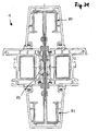
In den
Das Halteelement 1 umfasst im wesentlichen zwei thermisch voneinander getrennte Körper 2 und 3 und einen zwischen diesen beiden Körpern 2 und 3 angeordneten Isolator 4. Der Isolator 4 hat hinsichtlich seines Querschnittes eine knochenähnliche Gestalt, wobei er mit seinen beiden verdickten Seitenbereichen 5 und 6 in jeweils einem in Längsrichtung der Körper 2 und 3 verlaufenden Kanal 7 bzw. 8 angeordnet ist. Die beiden Kanäle 7 und 8 sind gegenüber ihrer Innenseite erweitert, sodass die Seitenbereiche 5 und 6 jeweils in dem Kanal 7 bzw. in dem Kanal 8 angeordnet sind und somit jeweils eine Fonnschlussverbindung zwischen den Körpern 2 und 3 gegenüber dem Isolator 4 gebildet ist.The holding
Die Körper 2 und 3 weisen jeweils noch einen weiteren Kanal 9 und 10 entlang ihrer Längserstreckung auf. In den Kanälen 9 und 10 ist jeweils ein Dorn 11 bzw. 12 eines Abdeckprofils 13 bzw. 14 angeordnet. Der Dorn 11 bzw. 12 ist der Gestalt, dass er jeweils mit dem Kanal 9 bzw. 10 eine formschlüssige Verbindung aufweist.The
Dies schließt aber nicht aus, dass der Kanal 9 bzw. 10 und der Dorn 11 bzw. 12 derart miteinander zusammenwirken, dass zwischen dem Kanal 9 und dem Dorn 11 bzw. dem Kanal 10 und dem Dorn 12 lediglich eine kraftschlüssige Verbindung vorhanden sein kann.However, this does not rule out that the
Des Weiteren umfasst das Halteelement 1 zwei Bauteile 15 und 16, wobei die Abdeckprofile 13 und 14 eine Art Sichtblende zur Überbrückung der voneinander beabstandet angeordneten Bauteile 15 und 16 bilden.Furthermore, the holding
Durch die thermisch voneinander getrennten Körper 2 und 3 aus einem Strangpress-Element können beispielsweise innere Kräfte bzw. innere Spannungen, die in das Halteelement 1 eingeleitet werden, besser auf den Isolator 4 und hierdurch zwischen den Körpern 2 und 3 übertragen werden. Hierdurch sind wesentlich stabilere Halteelemente 1 geschaffen worden, die insbesondere höhere Kräfte bzw. Lasten aufnehmen können. Insbesondere betrifft dies die beiden Verbindungen zwischen dem Isolator 4 und den Körpern 2 und 3.By the thermally separated
Um den Körper 2 beziehungsweise den Körper 3 des Halteelementes 1 jeweils an den Bauteilen 15 und 16 befestigen zu können, weisen die Körper 2 und 3 jeweils zwei Bauteilhaltestege 2A, 2B, 3A und 3B auf. Die Bauteilhaltestege 2A, 2B, 3A und 3B werden hierzu in entsprechende Nuten der Bauteile 15 und 16 angebracht.In order to be able to fasten the
Das Halteelement 1 kann alternativ auch einen von den Körpern 2 und 3 abweichenden Körper 17 aufweisen. Der Körper 17 hat einen Kanal 18, der eine wesentlich größere Tiefe aufweist als die vorhin erwähnten Kanäle 9 und 10. Hierdurch ist es möglich, den Körper 17 stabiler auszubilden. Ein verändertes Abdeckprofil 19 ist mittels eines stärkeren Domes 20 an dem Halteelement 1 angebracht.The holding
In einem weiteren Ausführungsbeispiel des Halteelementes 1 (siehe
Um beispielsweise ein Stahlprofil 22 an dem Halteelement 1 anzuordnen, umfasst das Halteelement 1 einen Körper 23, der anstelle eines Kanals 9, 10 oder 18 zur Aufnahme eines Domes 11, 12 oder 20 oder zusätzlich dazu einen Profilhaltesteg 24 aufweist. Der Profilhaltesteg 24 hat hierbei eine Bohrung 25 in der eine Schraube 26 angeordnet ist, welche das Stahlprofil 22 an dem Halteelement 1 befestigt.For example, to arrange a
Das Stahlprofil 22 besteht aus zwei Profilteilhälften 22A und 22B. Diese beiden Profilteilhälften 22A und 22B sind mittels der Schraube 26 derart an dem Profilhaltesteg 24 angeordnet, dass hierdurch das Stahlprofil 22 einen sich nach innen verengenden Kanal 22C bildet.The
Nach dem Ausführungsbeispiel der
Das Halteelement 1 umfasst in einem weiteren Ausführungsbeispiel (
Die weiteren Ausführungsbeispiele der
Insbesondere die Stahlprofile 29, 31, 32 und 34 bis 42 weisen jeweils einen Haltebereich 43 (hier nur exemplarisch in
Damit insbesondere auch ein Stahlprofil 35 lediglich eine möglichst geringe Kälte- bzw. Wärmebrücke darstellt, haben beispielsweise die Profilteilhälften 60 und 61 des Stahlprofils 35 in einen Bereich 62 jeweils eine Querschnittsreduzierung.Thus, in particular, a steel profile 35 only represents the lowest possible cold or thermal bridge, for example, the profile part halves 60 and 61 of the steel profile 35 in a
Es versteht sich, dass die Querschnittsreduzierung je nach Ausführungsbeispiel auch in anderen Bereichen eines Stahlprofils 29, 31, 32 und 34 bis 42 vorgesehen werden kann. Um insbesondere zwei Stahlprofile 36 und 37 an einem Profilhaltesteg 24 besonders einfach anzuordnen, ist das Stahlprofil 36 in einem Kanal 63 des Stahlprofils 37 angeordnet. Der Kanal 63 wird durch die beiden Profilteilhälften 64 und 65 des Stahlprofils 37 gebildet.It is understood that the cross-sectional reduction can be provided depending on the embodiment in other areas of a
Das Halteelement 1 (
In den
Die Körper 66 bis 71 stellen eine wesentlich schlechtere Kältebrücke dar, als die Aluminium-Körper aus den
Insbesondere die Halteelemente (1) aus den
Das Halteelement aus
Die Halteelemente aus den
Das Halteelement aus
In den
An den jeweiligen Körpern 73 bis 75 sind Profilelemente 76 bis 81 angeordnet. Insbesondere wenn die Körper 73, 74 und 75 nur geringe Lasten aufzunehmen haben, eignet sich ein Kunststoff für deren Herstellung besonders gut, da ein Kunststoff eine denkbar schlechte Kältebrücke zwischen einem Warmbereich und einem Kaltbereich darstellt.At the
Um Halteelemente für Hohlkammerprofile, insbesondere für Fensterrahmen, Fassadenelemente oder dergleichen weiterzuentwickeln, schlägt die Erfindung ein Halteelement mit mehreren Körpern vor, insbesondere zum Aufnehmen von Bauteilen wie Fensterrahmen, Fassadenelementen oder dergleichen, bei welchem wenigstens einer der Körper ein Strangpress-Element aufweist.In order to further develop holding elements for hollow chamber profiles, in particular for window frames, facade elements or the like, the invention proposes a holding element with a plurality of bodies, in particular for receiving components such as window frames, facade elements or the like, in which at least one of the bodies has an extrusion element.
Claims (30)
- A holding element (1) having a plurality of bodies (2, 3; 17; 21; 23; 28; 66 to 75), in particular for receiving components (15, 16) such as window frames, façade elements or the like, in which at least on of the bodies (2, 3; 17; 21; 23; 28; 66 to 75) has an extrusion press element, and two bodies are thermally separated by an insulator, wherein the extrusion press element consists of an aluminum alloy and the substance steel serves as reinforcement of the extrusion press element, characterized by a material composition in which the substance steel is removed at a greater distance from a cross-sectional insert (83) of the holding element (1) than the substance aluminum.
- The holding element (1) as specified in claim 1, characterized in that one of the bodies (2, 3; 17; 21; 23; 28; 66 to 75) consists of a solid.
- The holding element (1) as specified in one of the claims 1 to 2, characterized in that one of the bodies (2, 3; 17; 21; 23; 28; 66 to 75) has a reduced cross-section.
- The holding element (1) as specified in one of the claims 1 to 3, characterized in that the cross-section region of one the body (2, 3; 17; 21; 23; 28; 66 to 75) is reduced by material recesses.
- The holding element (1) as specified in one of the claims 1 to 4, characterized in that the body (2, 3; 17; 21; 23; 28; 66 to 75) has at least one canal (9, 10; 18) that extends in the longitudinal direction of the body (2, 3; 17; 21; 23; 28; 66 to 75).
- The holding element (1) as specified in claim 5, characterized in that the canal (9, 10; 18) that extends in the longitudinal direction of the body (2, 3; 17; 21; 23; 28; 66 to 75) is widened into a canal interior.
- The holding element (1) as specified in one of the claims 1 to 6, characterized in that at least one body (2, 3; 17; 21; 23; 28; 66 to 75) has a form-fitting connection with a thermal insulator (4) of the bodies (2, 3; 17; 21; 23; 28; 66 to 75).
- The holding element (1) as specified in one of the claims 1 to 7, characterized in that at least one body (2, 3; 17; 21; 23; 28; 66 to 75) has at least one profile holding web (24) extending in the longitudinal direction of the body (2, 3; 17; 21; 23; 28; 66 to 75).
- The holding element (1) as specified in one of the claims 1 to 8, characterized in that one of the bodies (2, 3; 17; 21; 23; 28; 66 to 75) has at least one component holding web (2A, 2B, 3A, 3B) preferably protruding in the component plane, said component holding web working together with the components (15, 16).
- The holding element (1) as specified in claim 9, characterized in that the component holding web (2A, 2B, 3A, 3B) and a profile holding web (24) of the holding element (1) are arranged at right angles to one another.
- The holding element (1) as specified in one of the claims 1 to 10, characterized in that especially one profile holding web (24) of at least one body (2, 3; 17; 21; 23; 28; 66 to 75) has at least one bore hole (25) for receiving a profile element (22, 27; 29, 30; 31, 32; 76, 77; 78, 79; 80, 81).
- The holding element (1) as specified in claim 11, characterized in that the profile element (22, 27; 29, 30; 31, 32; 76, 77; 78, 79; 80, 81) has a steel profile (22, 27; 29, 30; 31).
- The holding element (1) as specified in one of the claims 1 to 12, characterized in that at least one body (2, 3; 17; 21; 23; 28; 66 to 75) has a form-fitting connection with profile element (22, 27; 29, 30; 31, 32; 76, 77; 78, 79; 80, 81).
- The holding element (1) as specified in one of the claims 11 to 13, characterized in that the profile element (22, 27; 29, 30; 31, 32; 76, 77; 78, 79; 80, 81) is composed of at least two profile part halves (22A, 22B, 60, 61; 64, 65) that are connected by means of a bolted connection and/or by means of a casing (44) or a casing extension (53).
- The holding element (1) as specified in claim 14, characterized in that the profile part halves (22A, 22B, 60, 61; 64, 65) are connected by means of a bolted connection and/or by means of a casing (44) or a casing extension (53).
- The holding element (1) as specified in claim 15, characterized in that the casing (44) has a form-fitting and/or a friction-type connection in comparison to the casing extension (53).
- The holding element (1) as specified in one of the claims 10 to 16, characterized in that at least two profile part halves (22A, 22B, 60, 61; 64, 65) form in the longitudinal direction of the profile element (22, 27; 29, 30; 31, 32; 76, 77; 78, 79; 80, 81) a canal (22C; 63) preferably expanding to the canal interior.
- The holding element (1) as specified in claim 17, characterized in that at least one holding device is associated with a casing (44) in the canal (22C; 63).
- The holding element (1) as specified in one of the claims 1 to 18, characterized in that at least one profile part half (22A, 22B, 60, 61; 64, 65) of a first profile element (22, 27; 29, 30; 31, 32; 76, 77; 78, 79; 80, 81) is arranged between two profile part halves (22A, 22B, 60, 61; 64, 65) of a second profile element (22, 27; 29, 30; 31, 32; 76, 77; 78, 79; 80, 81).
- The holding element (1) as specified in one of the claims 1 to 19, characterized in that at least one profile part half (22A, 22B, 60, 61; 64, 65) of a profile element (22, 27; 29, 30; 31, 32; 76, 77; 78, 79; 80, 81) is arranged at least partially in a canal (22C; 63) of a further profile element (22, 27; 29, 30; 31, 32; 76, 77; 78, 79; 80, 81).
- The holding element (1) as specified in one of the claims 1 to 20, characterized in that a profile element (22, 27; 29, 30; 31, 32; 76, 77; 78, 79; 80, 81) has a holding region (43) that differs from a canal (22C; 63).
- The holding element (1) as specified in one of the claims 1 to 21, characterized in that at least one profile part half (22A, 22B, 60, 61; 64, 65) has a reduced cross-section, wherein the reduced cross-section is preferably arranged between two distanced holding regions of two profile elements (22, 27; 29, 30; 31, 32; 76, 77; 78, 79; 80, 81).
- The holding element (1) as specified in one of the claims 1 to 22, characterized in that at least one of the bodies (2, 3; 17; 21; 23; 28; 66 to 75) is longer in the longitudinal direction than an insulator (4) that is arranged thereon.
- The holding element (1) as specified in claim 23, characterized in that the insulator (4) is composed of a polyamide.
- The holding element (1) as specified in one of the claims 1 to 24, characterized in that the holding element (1) has one component, preferably two components (15, 16), on which the body (2, 3; 17; 21; 23; 28; 66 to 75) is arranged as reinforcement.
- The holding element (1) as specified in one of the claims 1 to 25, characterized in that the holding element (1) has varying rigidity in the direction of its maximal cross sectional extension (84).
- The holding element (1) as specified in one of the claims 1 to 26, characterized in that the holding element (1) has a varying modulus of elasticity in the direction of its maximal cross sectional extension (84).
- The holding element (1) as specified in one of the claims 1 to 27, characterized in that the holding element (1) has a varying modulus of elasticity value that decreases from one cross-sectional outer layer (82) to one cross-sectional inner layer (83).
- The holding element (1) as specified in one of the claims 1 to 28, characterized in that the holding element (1) has a material order that comprises the following substances from a cross-sectional outer layer (82) to a cross-sectional inner layer (83): steel, aluminum, and plastic.
- The use of a holding element (1) as specified in one of the claims 1 to 29, for receiving profile elements (22, 27; 29, 30; 31, 32; 76, 77; 78, 79; 80, 81), in particular for also receiving façade elements of the like.
Applications Claiming Priority (3)
| Application Number | Priority Date | Filing Date | Title |
|---|---|---|---|
| DE10156898A DE10156898A1 (en) | 2001-11-21 | 2001-11-21 | Holding element for window frames etc. has at least one body including extruded element |
| DE10156898 | 2001-11-21 | ||
| PCT/DE2002/003824 WO2003046323A1 (en) | 2001-11-21 | 2002-10-11 | Holding element, method for producing a holding element and use of extruded elements |
Publications (2)
| Publication Number | Publication Date |
|---|---|
| EP1448864A1 EP1448864A1 (en) | 2004-08-25 |
| EP1448864B1 true EP1448864B1 (en) | 2009-12-16 |
Family
ID=7706329
Family Applications (1)
| Application Number | Title | Priority Date | Filing Date |
|---|---|---|---|
| EP02776800A Expired - Lifetime EP1448864B1 (en) | 2001-11-21 | 2002-10-11 | Holding element und use of such a holding element |
Country Status (7)
| Country | Link |
|---|---|
| EP (1) | EP1448864B1 (en) |
| AT (1) | ATE452271T1 (en) |
| AU (1) | AU2002339356A1 (en) |
| DE (3) | DE10156898A1 (en) |
| DK (1) | DK1448864T3 (en) |
| HU (1) | HUP0402005A2 (en) |
| WO (1) | WO2003046323A1 (en) |
Families Citing this family (5)
| Publication number | Priority date | Publication date | Assignee | Title |
|---|---|---|---|---|
| EP1703064A1 (en) * | 2005-02-10 | 2006-09-20 | Veka AG | Method of coupling windows within a window arrangement and coupling system |
| DE102007015988B4 (en) | 2007-04-03 | 2018-06-21 | Gealan Fenster-Systeme Gmbh | Coupling fold block for connecting individual frames to a window front |
| DE102007026749A1 (en) * | 2007-06-09 | 2008-12-11 | Profine Gmbh | connection profile |
| DE102009038396A1 (en) | 2009-05-07 | 2010-11-11 | Helmut Over | Coupling element for coupling sections of e.g. window frame, has undercut grooves for receiving seals using locking foot and formed in aluminum part and steel sheet part, and sheet parts connected with each other in form of hooks |
| EP2248982B1 (en) | 2009-05-07 | 2015-01-28 | Over, Christa | Coupling element for window frames, facades or similar |
Family Cites Families (16)
| Publication number | Priority date | Publication date | Assignee | Title |
|---|---|---|---|---|
| CH471952A (en) * | 1968-03-08 | 1969-04-30 | Felix Andre | Assembly of metal construction elements for building facades |
| DE3502477A1 (en) * | 1985-01-25 | 1986-08-07 | Julius & August Erbslöh GmbH + Co, 5620 Velbert | CARRIERS, SUPPORTS, POST OR THE LIKE COMPOSED FROM SEVERAL PROFILE RODS, ESPECIALLY FOR FACADES |
| US4686805A (en) * | 1985-02-21 | 1987-08-18 | Jarl Extrusions, Inc. | Panel support |
| DE3614012A1 (en) * | 1986-04-25 | 1987-11-05 | Happich Gmbh Gebr | Device for lining a flange which projects from a vehicle body and is continuously bent in the free end region |
| DE8812237U1 (en) * | 1988-09-28 | 1988-11-17 | Over, Helmut, 5352 Zuelpich, De | |
| DE3841334C2 (en) * | 1988-12-08 | 1997-08-28 | Schueco Int Gmbh & Co | Window, door or fixed glazing |
| US5038537A (en) * | 1989-02-21 | 1991-08-13 | Harry Frambach | Window system and structure |
| DE4210998A1 (en) * | 1991-04-03 | 1992-10-22 | Papst Hans Dieter | Protective grid with fixed frame parts - has holder element formed as bar, with longitudinal groove in which side edge of surface pattern is accommodated |
| DE4140458C2 (en) * | 1991-12-05 | 1997-04-10 | Mannesmann Ag | Glass facade for vertical, diagonal and horizontal building systems |
| DE9207578U1 (en) * | 1992-06-04 | 1992-08-27 | Lenz, Hermann, 3554 Gladenbach, De | |
| DE4344863C2 (en) * | 1993-12-29 | 1995-10-26 | Schroff Gmbh | Fastening arrangement |
| DE4447208C2 (en) * | 1994-12-30 | 1998-07-16 | Alfer Aluminium Gmbh | Hook carrier system |
| DE19535757A1 (en) * | 1995-09-26 | 1997-03-27 | Transnorm System Gmbh | Flat conveyor belt transporter system |
| DE29604633U1 (en) * | 1996-03-13 | 1996-05-30 | Over Helmut | Glazing support |
| DE19802020A1 (en) * | 1998-01-21 | 1999-07-22 | Krauss Innovation Ltd | Fixture for heavy panes of glass forming part of a balcony |
| WO1999050511A1 (en) * | 1998-03-27 | 1999-10-07 | Helmut Over | Support for door frames, facades or the same |
-
2001
- 2001-11-21 DE DE10156898A patent/DE10156898A1/en not_active Withdrawn
-
2002
- 2002-10-11 HU HU0402005A patent/HUP0402005A2/en unknown
- 2002-10-11 AT AT02776800T patent/ATE452271T1/en active
- 2002-10-11 EP EP02776800A patent/EP1448864B1/en not_active Expired - Lifetime
- 2002-10-11 DE DE10295524T patent/DE10295524D2/en not_active Expired - Fee Related
- 2002-10-11 DK DK02776800.1T patent/DK1448864T3/en active
- 2002-10-11 WO PCT/DE2002/003824 patent/WO2003046323A1/en not_active Application Discontinuation
- 2002-10-11 AU AU2002339356A patent/AU2002339356A1/en not_active Abandoned
- 2002-10-11 DE DE50214109T patent/DE50214109D1/en not_active Expired - Lifetime
Also Published As
| Publication number | Publication date |
|---|---|
| EP1448864A1 (en) | 2004-08-25 |
| DE10156898A1 (en) | 2003-05-28 |
| WO2003046323A1 (en) | 2003-06-05 |
| ATE452271T1 (en) | 2010-01-15 |
| DE10295524D2 (en) | 2004-09-23 |
| AU2002339356A1 (en) | 2003-06-10 |
| HUP0402005A2 (en) | 2005-01-28 |
| DK1448864T3 (en) | 2010-04-26 |
| DE50214109D1 (en) | 2010-01-28 |
Similar Documents
| Publication | Publication Date | Title |
|---|---|---|
| EP0146716B1 (en) | Superstructure | |
| EP0479401B1 (en) | Impact beam | |
| EP0278292B1 (en) | Hollow shaft and method of manufacturing it | |
| EP0749378B1 (en) | Wiper blade | |
| EP1868885B1 (en) | Aircraft structural element provided with a cavity and drainage element | |
| DE102012020432B3 (en) | Door sill structure for vehicle body, has inner sill that encompasses outer sill with its concave surface side in form-fit manner, where contour of encompassed area of outer sill is adjusted to concave surface side | |
| WO2003037700A1 (en) | Light-weight component, especially body part | |
| DE102005011834B4 (en) | Lateral roof frame for a motor vehicle | |
| EP1504983A1 (en) | Vehicle subframe | |
| DE10329017B4 (en) | Carrying structure, in particular for body structures of vehicles made of rectangular hollow sections | |
| DE102012022876A1 (en) | Reinforcing element for amplifying longitudinal and lateral surfaces of multi-chamber hollow profile i.e. car body, has arm sections inserted into hollow section interior over insertion opening formed on side surface of hollow section | |
| EP1730016A1 (en) | Cross member or structural component for a motor vehicle | |
| DE19945160A1 (en) | Vehicle steering column | |
| EP1580343B1 (en) | Element for the butt joining of profiles | |
| DE2321915A1 (en) | Collapsible steering column assembly | |
| EP1448864B1 (en) | Holding element und use of such a holding element | |
| DE202008000574U1 (en) | connecting device | |
| EP3898296A1 (en) | Chassis link for a motor vehicle | |
| DE102006031190A1 (en) | Carrier for a motor vehicle chassis, especially the sill, is of two components bonded together with a hollow zone between them for increased occupant protection on a collision | |
| EP0418718A1 (en) | Hydraulically-damping bushing | |
| DE10130794A1 (en) | Structural part of a motor vehicle body and method for its production | |
| DE102015220088B3 (en) | Connection of an insert with a hollow profile | |
| EP2223844B1 (en) | Front-end module for vehicles | |
| DE19805804A1 (en) | Construction of bodywork for vehicle | |
| EP1491696B1 (en) | System for joining profiles |
Legal Events
| Date | Code | Title | Description |
|---|---|---|---|
| PUAI | Public reference made under article 153(3) epc to a published international application that has entered the european phase |
Free format text: ORIGINAL CODE: 0009012 |
|
| 17P | Request for examination filed |
Effective date: 20040621 |
|
| AK | Designated contracting states |
Kind code of ref document: A1 Designated state(s): AT BE BG CH CY CZ DE DK EE ES FI FR GB GR IE IT LI LU MC NL PT SE SK TR |
|
| AX | Request for extension of the european patent |
Extension state: AL LT LV MK RO SI |
|
| 17Q | First examination report despatched |
Effective date: 20080721 |
|
| GRAP | Despatch of communication of intention to grant a patent |
Free format text: ORIGINAL CODE: EPIDOSNIGR1 |
|
| RTI1 | Title (correction) |
Free format text: HOLDING ELEMENT UND USE OF SUCH A HOLDING ELEMENT |
|
| GRAS | Grant fee paid |
Free format text: ORIGINAL CODE: EPIDOSNIGR3 |
|
| GRAA | (expected) grant |
Free format text: ORIGINAL CODE: 0009210 |
|
| AK | Designated contracting states |
Kind code of ref document: B1 Designated state(s): AT BE BG CH CY CZ DE DK EE ES FI FR GB GR IE IT LI LU MC NL PT SE SK TR |
|
| AX | Request for extension of the european patent |
Extension state: AL LT LV MK RO SI |
|
| REG | Reference to a national code |
Ref country code: GB Ref legal event code: FG4D Free format text: NOT ENGLISH |
|
| REG | Reference to a national code |
Ref country code: CH Ref legal event code: EP |
|
| REG | Reference to a national code |
Ref country code: IE Ref legal event code: FG4D |
|
| REF | Corresponds to: |
Ref document number: 50214109 Country of ref document: DE Date of ref document: 20100128 Kind code of ref document: P |
|
| REG | Reference to a national code |
Ref country code: SE Ref legal event code: TRGR |
|
| REG | Reference to a national code |
Ref country code: NL Ref legal event code: T3 |
|
| REG | Reference to a national code |
Ref country code: CH Ref legal event code: NV Representative=s name: E. BLUM & CO. AG PATENT- UND MARKENANWAELTE VSP |
|
| REG | Reference to a national code |
Ref country code: DK Ref legal event code: T3 |
|
| PG25 | Lapsed in a contracting state [announced via postgrant information from national office to epo] |
Ref country code: FI Free format text: LAPSE BECAUSE OF FAILURE TO SUBMIT A TRANSLATION OF THE DESCRIPTION OR TO PAY THE FEE WITHIN THE PRESCRIBED TIME-LIMIT Effective date: 20091216 |
|
| LTIE | Lt: invalidation of european patent or patent extension |
Effective date: 20091216 |
|
| REG | Reference to a national code |
Ref country code: IE Ref legal event code: FD4D |
|
| PG25 | Lapsed in a contracting state [announced via postgrant information from national office to epo] |
Ref country code: EE Free format text: LAPSE BECAUSE OF FAILURE TO SUBMIT A TRANSLATION OF THE DESCRIPTION OR TO PAY THE FEE WITHIN THE PRESCRIBED TIME-LIMIT Effective date: 20091216 Ref country code: PT Free format text: LAPSE BECAUSE OF FAILURE TO SUBMIT A TRANSLATION OF THE DESCRIPTION OR TO PAY THE FEE WITHIN THE PRESCRIBED TIME-LIMIT Effective date: 20100416 Ref country code: BG Free format text: LAPSE BECAUSE OF FAILURE TO SUBMIT A TRANSLATION OF THE DESCRIPTION OR TO PAY THE FEE WITHIN THE PRESCRIBED TIME-LIMIT Effective date: 20100316 Ref country code: ES Free format text: LAPSE BECAUSE OF FAILURE TO SUBMIT A TRANSLATION OF THE DESCRIPTION OR TO PAY THE FEE WITHIN THE PRESCRIBED TIME-LIMIT Effective date: 20100327 Ref country code: IE Free format text: LAPSE BECAUSE OF FAILURE TO SUBMIT A TRANSLATION OF THE DESCRIPTION OR TO PAY THE FEE WITHIN THE PRESCRIBED TIME-LIMIT Effective date: 20091216 |
|
| PG25 | Lapsed in a contracting state [announced via postgrant information from national office to epo] |
Ref country code: CZ Free format text: LAPSE BECAUSE OF FAILURE TO SUBMIT A TRANSLATION OF THE DESCRIPTION OR TO PAY THE FEE WITHIN THE PRESCRIBED TIME-LIMIT Effective date: 20091216 Ref country code: SK Free format text: LAPSE BECAUSE OF FAILURE TO SUBMIT A TRANSLATION OF THE DESCRIPTION OR TO PAY THE FEE WITHIN THE PRESCRIBED TIME-LIMIT Effective date: 20091216 |
|
| PLBE | No opposition filed within time limit |
Free format text: ORIGINAL CODE: 0009261 |
|
| STAA | Information on the status of an ep patent application or granted ep patent |
Free format text: STATUS: NO OPPOSITION FILED WITHIN TIME LIMIT |
|
| PG25 | Lapsed in a contracting state [announced via postgrant information from national office to epo] |
Ref country code: GR Free format text: LAPSE BECAUSE OF FAILURE TO SUBMIT A TRANSLATION OF THE DESCRIPTION OR TO PAY THE FEE WITHIN THE PRESCRIBED TIME-LIMIT Effective date: 20100317 Ref country code: CY Free format text: LAPSE BECAUSE OF FAILURE TO SUBMIT A TRANSLATION OF THE DESCRIPTION OR TO PAY THE FEE WITHIN THE PRESCRIBED TIME-LIMIT Effective date: 20091216 |
|
| 26N | No opposition filed |
Effective date: 20100917 |
|
| PG25 | Lapsed in a contracting state [announced via postgrant information from national office to epo] |
Ref country code: IT Free format text: LAPSE BECAUSE OF FAILURE TO SUBMIT A TRANSLATION OF THE DESCRIPTION OR TO PAY THE FEE WITHIN THE PRESCRIBED TIME-LIMIT Effective date: 20091216 |
|
| BERE | Be: lapsed |
Owner name: OVER, HELMUT Effective date: 20101031 |
|
| PG25 | Lapsed in a contracting state [announced via postgrant information from national office to epo] |
Ref country code: BE Free format text: LAPSE BECAUSE OF NON-PAYMENT OF DUE FEES Effective date: 20101031 |
|
| PG25 | Lapsed in a contracting state [announced via postgrant information from national office to epo] |
Ref country code: TR Free format text: LAPSE BECAUSE OF FAILURE TO SUBMIT A TRANSLATION OF THE DESCRIPTION OR TO PAY THE FEE WITHIN THE PRESCRIBED TIME-LIMIT Effective date: 20091216 |
|
| REG | Reference to a national code |
Ref country code: DE Ref legal event code: R082 Ref document number: 50214109 Country of ref document: DE Representative=s name: PATENTANWALTSKANZLEI LIERMANN-CASTELL, PATENTA, DE |
|
| REG | Reference to a national code |
Ref country code: DE Ref legal event code: R081 Ref document number: 50214109 Country of ref document: DE Owner name: OVER, CHRISTA, DE Free format text: FORMER OWNER: OVER, HELMUT, 53909 ZUELPICH, DE Effective date: 20130809 Ref country code: DE Ref legal event code: R082 Ref document number: 50214109 Country of ref document: DE Representative=s name: PATENTANWALTSKANZLEI LIERMANN-CASTELL, PATENTA, DE Effective date: 20130809 Ref country code: DE Ref legal event code: R082 Ref document number: 50214109 Country of ref document: DE Representative=s name: PATENTANWALTSKANZLEI LIERMANN-CASTELL, DE Effective date: 20130809 |
|
| REG | Reference to a national code |
Ref country code: FR Ref legal event code: PLFP Year of fee payment: 14 |
|
| PGFP | Annual fee paid to national office [announced via postgrant information from national office to epo] |
Ref country code: LU Payment date: 20151023 Year of fee payment: 14 |
|
| PGFP | Annual fee paid to national office [announced via postgrant information from national office to epo] |
Ref country code: DK Payment date: 20151021 Year of fee payment: 14 |
|
| PGFP | Annual fee paid to national office [announced via postgrant information from national office to epo] |
Ref country code: GB Payment date: 20151021 Year of fee payment: 14 |
|
| PGFP | Annual fee paid to national office [announced via postgrant information from national office to epo] |
Ref country code: NL Payment date: 20151021 Year of fee payment: 14 Ref country code: SE Payment date: 20151021 Year of fee payment: 14 Ref country code: MC Payment date: 20151014 Year of fee payment: 14 |
|
| PGFP | Annual fee paid to national office [announced via postgrant information from national office to epo] |
Ref country code: DE Payment date: 20151221 Year of fee payment: 14 |
|
| REG | Reference to a national code |
Ref country code: FR Ref legal event code: PLFP Year of fee payment: 15 |
|
| REG | Reference to a national code |
Ref country code: DE Ref legal event code: R119 Ref document number: 50214109 Country of ref document: DE |
|
| REG | Reference to a national code |
Ref country code: DK Ref legal event code: EBP Effective date: 20161031 |
|
| REG | Reference to a national code |
Ref country code: NL Ref legal event code: MM Effective date: 20161101 |
|
| GBPC | Gb: european patent ceased through non-payment of renewal fee |
Effective date: 20161011 |
|
| PG25 | Lapsed in a contracting state [announced via postgrant information from national office to epo] |
Ref country code: MC Free format text: LAPSE BECAUSE OF NON-PAYMENT OF DUE FEES Effective date: 20161031 |
|
| PG25 | Lapsed in a contracting state [announced via postgrant information from national office to epo] |
Ref country code: DE Free format text: LAPSE BECAUSE OF NON-PAYMENT OF DUE FEES Effective date: 20170503 Ref country code: GB Free format text: LAPSE BECAUSE OF NON-PAYMENT OF DUE FEES Effective date: 20161011 |
|
| PG25 | Lapsed in a contracting state [announced via postgrant information from national office to epo] |
Ref country code: SE Free format text: LAPSE BECAUSE OF NON-PAYMENT OF DUE FEES Effective date: 20161012 Ref country code: LU Free format text: LAPSE BECAUSE OF NON-PAYMENT OF DUE FEES Effective date: 20161011 Ref country code: NL Free format text: LAPSE BECAUSE OF NON-PAYMENT OF DUE FEES Effective date: 20161101 |
|
| REG | Reference to a national code |
Ref country code: FR Ref legal event code: PLFP Year of fee payment: 16 |
|
| PG25 | Lapsed in a contracting state [announced via postgrant information from national office to epo] |
Ref country code: DK Free format text: LAPSE BECAUSE OF NON-PAYMENT OF DUE FEES Effective date: 20161031 |
|
| PGFP | Annual fee paid to national office [announced via postgrant information from national office to epo] |
Ref country code: FR Payment date: 20171024 Year of fee payment: 16 |
|
| PGFP | Annual fee paid to national office [announced via postgrant information from national office to epo] |
Ref country code: CH Payment date: 20171019 Year of fee payment: 16 |
|
| PGFP | Annual fee paid to national office [announced via postgrant information from national office to epo] |
Ref country code: AT Payment date: 20181022 Year of fee payment: 17 |
|
| REG | Reference to a national code |
Ref country code: CH Ref legal event code: PL |
|
| PG25 | Lapsed in a contracting state [announced via postgrant information from national office to epo] |
Ref country code: CH Free format text: LAPSE BECAUSE OF NON-PAYMENT OF DUE FEES Effective date: 20181031 Ref country code: FR Free format text: LAPSE BECAUSE OF NON-PAYMENT OF DUE FEES Effective date: 20181031 Ref country code: LI Free format text: LAPSE BECAUSE OF NON-PAYMENT OF DUE FEES Effective date: 20181031 |
|
| REG | Reference to a national code |
Ref country code: AT Ref legal event code: MM01 Ref document number: 452271 Country of ref document: AT Kind code of ref document: T Effective date: 20191011 |
|
| PG25 | Lapsed in a contracting state [announced via postgrant information from national office to epo] |
Ref country code: AT Free format text: LAPSE BECAUSE OF NON-PAYMENT OF DUE FEES Effective date: 20191011 |