EP1447952B1 - Verfahren und Einrichtung zur Analyse eines OFDM-Signals - Google Patents
Verfahren und Einrichtung zur Analyse eines OFDM-Signals Download PDFInfo
- Publication number
- EP1447952B1 EP1447952B1 EP04000541A EP04000541A EP1447952B1 EP 1447952 B1 EP1447952 B1 EP 1447952B1 EP 04000541 A EP04000541 A EP 04000541A EP 04000541 A EP04000541 A EP 04000541A EP 1447952 B1 EP1447952 B1 EP 1447952B1
- Authority
- EP
- European Patent Office
- Prior art keywords
- signal
- bandwidth
- offset
- ofdm
- multiplier
- Prior art date
- Legal status (The legal status is an assumption and is not a legal conclusion. Google has not performed a legal analysis and makes no representation as to the accuracy of the status listed.)
- Expired - Fee Related
Links
- 238000000034 method Methods 0.000 title claims description 16
- 238000005070 sampling Methods 0.000 claims description 16
- 238000001228 spectrum Methods 0.000 claims description 14
- 238000012935 Averaging Methods 0.000 claims description 7
- 238000001914 filtration Methods 0.000 claims description 7
- 239000000969 carrier Substances 0.000 description 24
- 238000012546 transfer Methods 0.000 description 10
- 238000005259 measurement Methods 0.000 description 9
- 238000010586 diagram Methods 0.000 description 8
- 238000012545 processing Methods 0.000 description 7
- 238000004458 analytical method Methods 0.000 description 4
- 230000000694 effects Effects 0.000 description 4
- 230000003595 spectral effect Effects 0.000 description 4
- 238000012952 Resampling Methods 0.000 description 3
- 230000005540 biological transmission Effects 0.000 description 3
- 238000004422 calculation algorithm Methods 0.000 description 3
- 238000004364 calculation method Methods 0.000 description 3
- 238000013461 design Methods 0.000 description 3
- 238000004088 simulation Methods 0.000 description 3
- 238000012360 testing method Methods 0.000 description 3
- 238000010606 normalization Methods 0.000 description 2
- 230000007704 transition Effects 0.000 description 2
- 108010074864 Factor XI Proteins 0.000 description 1
- 108091023242 Internal transcribed spacer Proteins 0.000 description 1
- 238000007476 Maximum Likelihood Methods 0.000 description 1
- 239000000654 additive Substances 0.000 description 1
- 230000000996 additive effect Effects 0.000 description 1
- 238000006243 chemical reaction Methods 0.000 description 1
- 125000004122 cyclic group Chemical group 0.000 description 1
- 230000007423 decrease Effects 0.000 description 1
- 230000001419 dependent effect Effects 0.000 description 1
- 238000011161 development Methods 0.000 description 1
- 230000018109 developmental process Effects 0.000 description 1
- 230000001629 suppression Effects 0.000 description 1
Images
Classifications
-
- H—ELECTRICITY
- H04—ELECTRIC COMMUNICATION TECHNIQUE
- H04L—TRANSMISSION OF DIGITAL INFORMATION, e.g. TELEGRAPHIC COMMUNICATION
- H04L27/00—Modulated-carrier systems
- H04L27/26—Systems using multi-frequency codes
- H04L27/2601—Multicarrier modulation systems
- H04L27/2647—Arrangements specific to the receiver only
- H04L27/2655—Synchronisation arrangements
-
- H—ELECTRICITY
- H04—ELECTRIC COMMUNICATION TECHNIQUE
- H04L—TRANSMISSION OF DIGITAL INFORMATION, e.g. TELEGRAPHIC COMMUNICATION
- H04L27/00—Modulated-carrier systems
- H04L27/26—Systems using multi-frequency codes
- H04L27/2601—Multicarrier modulation systems
- H04L27/2647—Arrangements specific to the receiver only
-
- H—ELECTRICITY
- H04—ELECTRIC COMMUNICATION TECHNIQUE
- H04L—TRANSMISSION OF DIGITAL INFORMATION, e.g. TELEGRAPHIC COMMUNICATION
- H04L27/00—Modulated-carrier systems
- H04L27/0014—Carrier regulation
- H04L2027/0083—Signalling arrangements
- H04L2027/0087—Out-of-band signals, (e.g. pilots)
-
- H—ELECTRICITY
- H04—ELECTRIC COMMUNICATION TECHNIQUE
- H04L—TRANSMISSION OF DIGITAL INFORMATION, e.g. TELEGRAPHIC COMMUNICATION
- H04L27/00—Modulated-carrier systems
- H04L27/26—Systems using multi-frequency codes
- H04L27/2601—Multicarrier modulation systems
- H04L27/2647—Arrangements specific to the receiver only
- H04L27/2655—Synchronisation arrangements
- H04L27/2668—Details of algorithms
- H04L27/2673—Details of algorithms characterised by synchronisation parameters
- H04L27/2675—Pilot or known symbols
-
- H—ELECTRICITY
- H04—ELECTRIC COMMUNICATION TECHNIQUE
- H04W—WIRELESS COMMUNICATION NETWORKS
- H04W28/00—Network traffic management; Network resource management
- H04W28/16—Central resource management; Negotiation of resources or communication parameters, e.g. negotiating bandwidth or QoS [Quality of Service]
- H04W28/18—Negotiating wireless communication parameters
-
- H—ELECTRICITY
- H04—ELECTRIC COMMUNICATION TECHNIQUE
- H04W—WIRELESS COMMUNICATION NETWORKS
- H04W48/00—Access restriction; Network selection; Access point selection
- H04W48/08—Access restriction or access information delivery, e.g. discovery data delivery
-
- H—ELECTRICITY
- H04—ELECTRIC COMMUNICATION TECHNIQUE
- H04W—WIRELESS COMMUNICATION NETWORKS
- H04W84/00—Network topologies
- H04W84/02—Hierarchically pre-organised networks, e.g. paging networks, cellular networks, WLAN [Wireless Local Area Network] or WLL [Wireless Local Loop]
- H04W84/10—Small scale networks; Flat hierarchical networks
- H04W84/12—WLAN [Wireless Local Area Networks]
Definitions
- This application concerns a simplified analysis of an OFDM (Orthogonal Erequency Division Multiplex)-signal, especially an OFDM signal for Wireless LAN as defined in IEEE802.11a, Part 11: "Wireless LAN Medium Access Control (MAC) and Physical Layer (PHY) specifications” referred herein as IEEE W-LAN Standard.
- OFDM Orthogonal Erequency Division Multiplex
- a receiver design for wireless broad-band systems is known from Speth, Fechtel, Fock, Meyr: “Optimum Receiver Design for Wireless Broad-Band Systems Using OFDM - Part I", IEEE Trans. On Comm. Vol. 47, No. 11, Nov. 1999, pages 1668 - 1677 and Speth, Fmül, Fock, Meyr: “Optimum Receiver Design for Wireless Broad-Band Systems Using OFDM - Part II", IEEE Trans. On Comm. Vol. 49, No. 4, April 2001, pages 571 - 578 .
- Document US 4,896,102 A describes a spectrum analyzer for analyzing an input spectrum.
- the analyzer includes a down converter capable of converting blocks or portions of the input spectrum to the corresponding predetermined output band of frequencies.
- a stepping device associated with the down converter subsequently selects portions of the input spectrum for conversion by the down converter.
- An A/D converter converts the output of the block converter into digital signals.
- a digital filter selects a predetermined frequency band from the predetermined output band of the frequencies of the block converter.
- the processing unit effects FFT operation on data contained within the predetermined frequency band.
- a memory device sequentially stores the output from the processing unit.
- the signal of wireless LAN systems is analysed in order to monitor the signal quality.
- the error vector magnitude EVM of the whole signal or of specific sub-carriers is a typical parameter to describe the signal quality.
- the object is solved by the features of claim 1 concerning the method and by the features of claim 9 concerning the analysing device.
- the spectrum of the OFDM signal can be shifted so that different parts of the OFDM spectrum can lie within the reduced bandwidth of the analysing device.
- Low pass filtering is necessary to suppress the mirror frequency and to limit the input bandwidth for a resampler following in the signal path.
- the length of the impulse response of the low pass filter is shorter than the length of the guard periods of the data symbols.
- the OFDM signal especially the OFDM signal for wireless LAN application, generally has several pilot channels at specific carrier frequencies. According to IEEE W-LAN standard there are four carrier frequencies transporting a pilot signal.
- the analysing device has a reduced bandwidth, not all pilot channels lie within the reduced bandwidth of the analysing device. For example, the number of useable pilot channels can be reduced from four to two.
- the analysing device has to estimate several synchronisation parameters of the OFDM signal, e.g. frequency offset, time or clock offset, phase offset resulting from the frequency offset and the clock offset and the gain. The accuracy of the estimation of these parameters is reduced due to the fact that only a reduced number of pilot channels can be used for the estimation. According to another aspect of the present invention this is compensated by averaging the estimated synchronisation parameters in OFDM-symbol direction in order to achieve the same accuracy which would apply to the use of the original number of pilot channels.
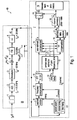
- the diagram of the interesting blocks of analysing device 40 is shown in fig. 1 .
- the resulting IF signal r IF ( t ) is shown on the left-hand side of fig. 1 .
- ADC analog to digital converter
- the subsequent digital down converter 4 shifts the IF signal to the complex base band.
- the base band signal is filtered by a FIR filter 5.
- the subsequent digital signal processing is shown and designated as W-LAN application block 7.
- the packet search is performed.
- This block 8 detects the long symbol LS and recovers the timing.
- the coarse timing is detected first.
- This search is preferably implemented in the time domain.
- a coarse estimate ⁇ f ⁇ coarse of the receiver-transmitter Rx-Tx frequency offset ⁇ f is derived from the metric. This can easily be understood because the phase of r ( i ) ⁇ r * ( i + N ) is determined by the frequency offset. As the frequency deviation ⁇ f can exceed half a bin (distance between neighbour sub-carriers) the preceding short symbol SS is also analysed in order to detect the ambiguity.
- the position of the long symbol LS is known and the starting point of the useful part of the first payload symbol can be derived.
- this calculated time instant is used to position the payload window. Only the payload part is windowed. This is sufficient because the payload is the only subject of the subsequent measurements.
- the windowed sequence is compensated by the coarse frequency estimate ⁇ f ⁇ coarse . This is necessary because otherwise inter channel interference (ICI) would occur in the frequency domain.
- ICI inter channel interference
- the transition to the frequency domain is achieved by a fast fourier transform FFT of e.g. length 64 in block 11.
- the FFT is performed symbolwise for everyone of the nof_symbols symbols of the payload.
- r l , k K mod ⁇ a l , k ⁇ H k ⁇ e j ⁇ 2 ⁇ ⁇ ⁇ N s / N ⁇ ⁇ k ⁇ l + n l , k with
- both the phase drift ⁇ k caused by the not yet compensated frequency deviation ⁇ f and the clock deviation ⁇ may not be neglected.
- ⁇ max 20 ppm.
- nof _ symbols 400 symbols is assumed.
- the example shows that it is also necessary to estimate and compensate the clock deviation, which is accomplished in the estimation block 12 using pilot table 13 and in the compensation blocks 14 and 15.
- the FFT must be followed by the joint estimation of the gain g , the fine frequency deviation ⁇ f and the clock deviation ⁇ .
- the tracking of the gain g is supported symbol for symbol.
- the coarse channel transfer function H ⁇ k coarse is calculated. This is useful because before symbol estimation the sequence r ' l,k is compensated by the coarse channel transfer function H ⁇ k coarse . Consequently a potential change of the gain at the symbol l (caused, for example, by the increase of DUT amplifier temperature) would increase the symbol error rate especially at large symbol alphabet M of the MQAM transmission. In this case the estimation and the subsequent compensation of the gain is useful. In the subsequent formulas the gain at the symbol l will be described by the parameter g l .
- the sequence r l , k is compensated in the compensation blocks 14 and 15.
- the compensation is user-defined i.e. the user determines which of the three parameters are compensated in compensation block 14. This is useful in order to extract the influence of these parameters.
- the resulting output sequence is described by r' l,k .
- the full compensation is always performed in compensation block 15. This separate compensation is necessary in order to avoid symbol errors.
- the secure estimation of the data symbols â / ,k is performed. From equation (1) it is clear that first the channel transfer function H k must be removed. This is achieved by dividing the known coarse channel estimate H ⁇ k coarse calculated from the LS. Usually an error free estimation of the data symbols can be assumed.
- r' l,k is divided by the improved estimates ⁇ k .
- the resulting channel compensated sequence is described by r'' l,k .
- the measurement variables are calculated.
- This parameter is equivalent to the so-called “RMS average of all errors Error RMS" of the IEEE802.11a measurement commandment, see IEEE W-LAN Standard, Chapter 17.3.9.7.
- Fig. 1 describes the W-LAN signal processing using a wideband signal section 20, such as Rohde & Schwarz device FSQ.
- the available bandwidth of the FSQ is 27 MHz and therefore sufficient to measure the IEEE802.11a signal with a bandwidth of 16.4 MHz.
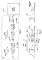
- fig. 2 the diagram of the interesting blocks of signal section 20 is shown.
- the IF signal is not yet bandlimited.
- the bandwidth BW A of signal section 20 of 8 MHz is modelled by the subsequent IF filter 21 with the frequency transfer function H IF ( f ).
- the schematic spectrum R IF ( f ) of the input signal is shown in fig. 3 .
- the bandwidth BW OFDM of the spectrum of the OFDM signal and the reduced bandwidth BW A of the analysing device 40 are indicated in fig. 3 .
- the schematic transfer function H IF (f) is shown in fig. 3 .
- the passband bandwidth BW A of the example is 8 MHz and symmetric to the IF frequency.
- the sub-carriers in the undistorted passband will be analysed.
- the main task of the IF filter 21 is to avoid aliasing effects in the 8 MHz analysing window by the subsequent sampling process of the Analog to Digital Converter (ADC) 22.
- This complex multiplication effects a spectral shift from the IF frequency f IF to base band.
- the following low pass filter 24 with the transfer function H LP ( f ) also possesses the passband bandwidth of 8 MHz, see schematic plot in fig. 3 , and fulfils two tasks:
- sampling must be changed to the Nyquist rate.
- This is performed by a digital resampler 25.
- the resampled sequence is multiplied with the sequence e -j ⁇ offset *iT s2 in multiplier 26.
- This operation generates a further spectral shift by the frequency f offset .
- This spectral shift can be integrated in the first downconversion, if the resampling process does not require a low pass input sequence.
- the resulting output sequence is r ( i ).
- the sequence r ( i ) enters into the W-LAN application 7 which is identical to the wideband FSQ implementation shown in fig. 1 .
- the sequence r ( i ) enters into the W-LAN application 7 which is identical to the wideband FSQ implementation shown in fig. 1 .
- the lower part of fig. 1 .
- the length ⁇ of the impulse response h ( t ) the low pass filter 24 is shorter than the length T GA of the guard periods of the data symbols.
- T GA the length of the guard periods of the data symbols.
- the impulse response h ( t ) of low pass filter 24 has a specific length ⁇ .
- ⁇ There are several possibilities to define the length ⁇ of the impulse response h ( t ).
- the impulse response h ( t ) decreases from starting value A to value 1/e ⁇ A within the time period ⁇ which can be used as a definition of the length ⁇ of the impulse response h ( t ).
- the length r of the impulse response of low pass filter 24 is defined as the inverse 1/ BW A of the bandwidth BW A of the low pass filter 24.
- ISI inter symbol interference
- this bandlimited measurement supports symbolwise tracking. This is possible because there are according to the invention always 2 pilot sub-carriers of the total 4 pilot sub-carriers within the 8 MHz analysing window.
- the pilots are used for symbolwise tracking, i.e. optional phase and/or timing and/or gain.
- the smaller number of used pilot carriers (2 instead of usually 4) leads to a higher estimation error of the synchronisation parameters ⁇ f ⁇ l , ⁇ l and consequently to an increase of the EVM compared to a measurement with no limitation of the bandwidth.
- the statistical increase can be calculated however and can be compensated by averaging the synchronisation parameters ⁇ f ⁇ l , ⁇ l over several data symbols.
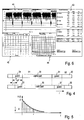
- Fig. 6 shows a typical screen plot of an analysing device 40.
- Section 41 shows the bursts of a specific sub-carrier of the OFDM signal.
- Section 42 shows the constellation diagram on a specific sub-carrier.
- Section 43 indicates EVM of all carriers, of the data carriers, the pilot carriers and the free carriers. Further, the IQ-Offset, IQ-Imbalance and quadrature mismatch are shown.
- Section 44 shows a diagram with EVM as a function of the sub-carrier number.
Landscapes
- Engineering & Computer Science (AREA)
- Computer Networks & Wireless Communication (AREA)
- Signal Processing (AREA)
- Digital Transmission Methods That Use Modulated Carrier Waves (AREA)
- Mobile Radio Communication Systems (AREA)
Claims (9)
- Verfahren zur Analyse eines Signals mit einer Analysevorrichtung (40), die einen Signalabschnitt (20) mit einer Bandbreite BWA aufweist, welche kleiner ist als die Bandbreite BWOFDM des zu analysierenden Signals,
wobei das Verfahren gekennzeichnet ist durch- Empfangen eines Eingangssignals (rIF(t)) bei einer Zwischenfrequenz (IF), wobei das Eingangssignal ein OFDM-Signal ist, welches eine Reihe von Datensymbolen auf mehreren orthogonalen Trägerfrequenzen überträgt und eine erste bestimmte Zahl von Trägerfrequenzen aufweist, die ein Pilotsignal innerhalb der Bandbreite BWOFDM übertragen,
wobei das Spektrum des OFDM-Signals (RIF(f)) um einen durch einen Benutzer festlegbaren Frequenzversatz (foffset) verschoben wird,- Filtern des OFDM-Signals (RIF(f)) mit einem ersten Filter (21) mit der Bandbreite BWA, die symmetrisch um die Zwischenfrequenz (IF) liegt,- anschließendes Abtasten des Ausgangssignals des ersten Filters (21) mit einer ersten Abtasteinrichtung (22) bei bzw. mit einer ersten Abtastrate (fs1),- Multiplizieren des abgetasteten Signals mit einer ersten Multipliziereinrichtung (23) mit einer ersten Multiplikatorfolge e-jω IF*iT s1,
wobei die Multiplikatorfolge eine erste Abtastperiode Ts1, einen ersten Zeitindex i und eine Winkelfrequenz ωIF bezüglich der Zwischenfrequenz (IF) enthält,- Tiefpassfiltern des Ausgangssignals der ersten Multipliziereinrichtung (23) mit einem zweiten Filter (24) mit der Bandbreite BWA,- Abtasten des Ausgangssignals des zweiten Filters mit einer zweiten Abtasteinrichtung (25) bei bzw. mit einer zweiten Abtastrate (fS2),- Abgeben eines Ausgangssignals (r(i)) durch Multiplizieren des durch die zweite Abtasteinrichtung (25) abgetasteten Signals mit einer zweiten Multipliziereinrichtung (26) mit einer zweiten Multiplikatorfolge e-jω offset *iT s2,
wobei die zweite Multiplikatorfolge eine zweite Abtastperiode Ts2, einen zweiten Zeitindex i und einen durch einen Benutzer festlegbaren Winkelfrequenzversatz ωoffset aufweist,- Schätzen von Synchronisationsparametern des Ausgangssignals (r(i)) durch Heranziehen einer zweiten bestimmten Zahl von Trägerfrequenzen, welche die Pilotsignale innerhalb der Bandbreite des Ausgangssignals (r(i)) übertragen,
wobei die zweite bestimmte Zahl von Trägerfrequenzen kleiner ist als die erste bestimmte Zahl,- Mitteln der geschätzten Synchronisationsparameter über mehrere Datensymbole, um die verringerte Zahl von Trägerfrequenzen zu kompensieren, welche das Pilotsignal innerhalb der Bandbreite des Ausgangssignals (r(i)) übertragen. - Verfahren nach Anspruch 1,
dadurch gekennzeichnet,
dass die erste bestimmte Zahl 4 ist und dass die zweite bestimmte Zahl 2 ist. - Verfahren nach Anspruch 1 oder 2,
dadurch gekennzeichnet,
dass die geschätzten Synchronisationsparameter des OFDM-Signals ein symbolweiser Frequenzversatz (Δf̂ 1) und/oder Taktversatz (ξ̂1) und/oder ein daraus resultierender Phasenversatz sind. - Verfahren nach einem der Ansprüche 1 bis 3,
dadurch gekennzeichnet,
dass jedes Datensymbol (S1) einen durch ein Schutzintervall (31) von benachbarten Datensymbolen (S2) getrennten nutzbaren Teil (30) aufweist,
wobei die Länge (τ) der Impulsantwort (h(t)) des Tiefpassfilters (24) kürzer ist als die Länge (TGP) der Schutzintervalle (31) der Datensymbole (S1, S2, ...). - Verfahren nach Anspruch 4,
dadurch gekennzeichnet,
dass die Länge (τ) der Impulsantwort (h(t)) des Tiefpassfilters (24) kürzer ist als 1/4 der Länge der Schutzintervalle (31) der Datensymbole (S1, S2, ...). - Verfahren nach einem der Ansprüche 1 bis 5,
dadurch gekennzeichnet,
dass die Schätzung der Synchronisationsparameter für jedes Symbol des Pilotsignals vorgenommen und über mehrere Symbole gemittelt wird. - Verfahren nach Anspruch 6,
dadurch gekennzeichnet,
dass die Länge (τ) der Impulsantwort (h(t)) des Tiefpassfilters (24) 2,5/16 der Länge der Schutzintervalle (31) der Datensymbole (S1, S2, ...) beträgt. - Analysevorrichtung (40) zur Analyse eines Signals mit einer Analysevorrichtung (40), die einen Signalabschnitt (20) mit einer Bandbreite BWA aufweist, welche kleiner ist als die Bandbreite BWOFDM des zu analysierenden Signals, wobei die Vorrichtung umfasst- einen Empfänger zum Empfangen eines Eingangssignals (rIF(t)) bei einer Zwischenfrequenz (IF), wobei das Eingangssignal ein OFDM-Signal ist, welches eine Reihe von Datensymbolen auf mehreren orthogonalen Trägerfrequenzen überträgt und eine erste bestimmte Zahl von Trägerfrequenzen aufweist, die ein Pilotsignal innerhalb der Bandbreite BWOFDM übertragen, wobei das Spektrum des OFDM-Signals (RIF(f)) um einen durch einen Benutzer festlegbaren Frequenzversatz (foffset) verschoben wird bzw. ist,- ein erstes Filter (21) mit der Bandbreite BWA, die symmetrisch um die Zwischenfrequenz (IF) liegt, zum Filtern des OFDM-Signals (RIF(f)),- eine erste Abtasteinrichtung (22) zum anschließenden Abtasten des Ausgangssignals des ersten Filters (21) bei bzw. mit einer ersten Abtastrate (fs1),- eine erste Multipliziereinrichtung (23) zum Multiplizieren des abgetasteten Signals mit einer ersten Multiplikatorfolge e-jω IF *iT s1,
wobei die Multiplikatorfolge eine erste Abtastperiode Ts1, einen ersten Zeitindex i und eine Winkelfrequenz ωIF bezüglich der Zwischenfrequenz (IF) aufweist,- ein zweites Filter (24) mit der Bandbreite BWA zum Tiefpassfiltern des Ausgangssignals der ersten Multipliziereinrichtung (23),- eine zweite Abtasteinrichtung (25) zum Abtasten des Ausgangssignals des zweiten Filters bei bzw. mit einer zweiten Abtastrate (fS2),- eine zweite Multipliziereinrichtung (26) zur Abgabe eines Ausgangssignals (r(i)) durch Multiplizieren des durch die zweite Abtasteinrichtung (25) abgetasteten Signals mit einer zweiten Multiplikatorfolge e-jω offset *iT s2,
wobei die zweite Multiplikatorfolge eine zweite Abtastperiode Ts2, einen zweiten Zeitindex i und einen durch einen Benutzer festlegbaren Winkelfrequenzversatz ωoffset aufweist,- eine Schätzeinrichtung (12) zum Schätzen von Synchronisationsparametern des Ausgangssignals (r(i)) durch Heranziehen einer zweiten bestimmten Zahl von Trägerfrequenzen, welche die Pilotsignale innerhalb der Bandbreite des Ausgangssignals (r(i)) übertragen,
wobei die zweite bestimmte Zahl von Trägerfrequenzen kleiner ist als die erste bestimmte Zahl,- eine Mittelungseinrichtung (19) zum Mitteln der geschätzten Synchronisationsparameter über mehrere Datensymbole, um die verringerte Zahl von Trägerfrequenzen zu kompensieren, welche das Pilotsignal innerhalb der Bandbreite des Ausgangssignals (r(i)) übertragen. - Computerprogrammprodukt, umfassend Programmcodemittel zum Ausführen sämtlicher Schritte eines der Ansprüche 1 bis 7, wenn das Programm auf einem programmierbaren Computer oder einem digitalen Signalprozessor abläuft bzw. durchgeführt wird.
Priority Applications (1)
| Application Number | Priority Date | Filing Date | Title |
|---|---|---|---|
| EP04000541A EP1447952B1 (de) | 2002-12-09 | 2003-03-03 | Verfahren und Einrichtung zur Analyse eines OFDM-Signals |
Applications Claiming Priority (4)
| Application Number | Priority Date | Filing Date | Title |
|---|---|---|---|
| EP02027409 | 2002-12-09 | ||
| EP02027409 | 2002-12-09 | ||
| EP04000541A EP1447952B1 (de) | 2002-12-09 | 2003-03-03 | Verfahren und Einrichtung zur Analyse eines OFDM-Signals |
| EP03004669A EP1445906B1 (de) | 2002-12-09 | 2003-03-03 | Verfahren und Vorrichtung zum Analysieren eines OFDM-Signals |
Related Parent Applications (2)
| Application Number | Title | Priority Date | Filing Date |
|---|---|---|---|
| EP03004669A Division EP1445906B1 (de) | 2002-12-09 | 2003-03-03 | Verfahren und Vorrichtung zum Analysieren eines OFDM-Signals |
| EP03004669.2 Division | 2003-03-03 |
Publications (2)
| Publication Number | Publication Date |
|---|---|
| EP1447952A1 EP1447952A1 (de) | 2004-08-18 |
| EP1447952B1 true EP1447952B1 (de) | 2011-06-22 |
Family
ID=32658180
Family Applications (2)
| Application Number | Title | Priority Date | Filing Date |
|---|---|---|---|
| EP03004669A Expired - Fee Related EP1445906B1 (de) | 2002-12-09 | 2003-03-03 | Verfahren und Vorrichtung zum Analysieren eines OFDM-Signals |
| EP04000541A Expired - Fee Related EP1447952B1 (de) | 2002-12-09 | 2003-03-03 | Verfahren und Einrichtung zur Analyse eines OFDM-Signals |
Family Applications Before (1)
| Application Number | Title | Priority Date | Filing Date |
|---|---|---|---|
| EP03004669A Expired - Fee Related EP1445906B1 (de) | 2002-12-09 | 2003-03-03 | Verfahren und Vorrichtung zum Analysieren eines OFDM-Signals |
Country Status (3)
| Country | Link |
|---|---|
| US (1) | US7492700B2 (de) |
| EP (2) | EP1445906B1 (de) |
| JP (1) | JP4359492B2 (de) |
Families Citing this family (20)
| Publication number | Priority date | Publication date | Assignee | Title |
|---|---|---|---|---|
| IL159173A0 (en) * | 2003-12-03 | 2004-06-01 | Zion Hadad | Ofdm communication channel |
| EP1601129B1 (de) * | 2004-05-27 | 2008-09-03 | Synad Technologies Limited | Verfahren zum Bestimmen der echten Fehlervektorgröße in einem drahtlosen lokalen Netzwerk |
| US7769372B1 (en) * | 2004-07-08 | 2010-08-03 | National Semiconductor Corporation | Selectively activated multi-subcarrier (SAMS) radio transceiver measuring techniques |
| US8325863B2 (en) * | 2004-10-12 | 2012-12-04 | Qualcomm Incorporated | Data detection and decoding with considerations for channel estimation errors due to guard subbands |
| US7751470B2 (en) * | 2005-02-07 | 2010-07-06 | Tektronix, Inc. | Time correlation of signal power to distortion characteristics |
| US8144824B2 (en) * | 2005-03-10 | 2012-03-27 | Qualcomm Incorporated | Trend influenced time tracking |
| US20060221810A1 (en) * | 2005-03-10 | 2006-10-05 | Bojan Vrcelj | Fine timing acquisition |
| US20100157833A1 (en) * | 2005-03-10 | 2010-06-24 | Qualcomm Incorporated | Methods and systems for improved timing acquisition for varying channel conditions |
| US8675631B2 (en) * | 2005-03-10 | 2014-03-18 | Qualcomm Incorporated | Method and system for achieving faster device operation by logical separation of control information |
| EP1727324A1 (de) * | 2005-05-25 | 2006-11-29 | Siemens Aktiengesellschaft | Funk-Übertragung mit variabler Länge des Guard Intervals |
| KR100699490B1 (ko) * | 2005-08-22 | 2007-03-26 | 삼성전자주식회사 | 샘플링 주파수 오프셋 추정방법 및 이 방법이 적용되는ofdm 시스템 |
| US7706250B2 (en) | 2005-09-23 | 2010-04-27 | Litepoint Corp. | Apparatus and method for simultaneous testing of multiple orthogonal frequency division multiplexed transmitters with single vector signal analyzer |
| US7822130B2 (en) * | 2005-09-23 | 2010-10-26 | Litepoint Corporation | Apparatus and method for simultaneous testing of multiple orthogonal frequency division multiplexed transmitters with single vector signal analyzer |
| US7623607B2 (en) * | 2005-10-31 | 2009-11-24 | Qualcomm Incorporated | Methods and apparatus for determining timing in a wireless communication system |
| US8948329B2 (en) * | 2005-12-15 | 2015-02-03 | Qualcomm Incorporated | Apparatus and methods for timing recovery in a wireless transceiver |
| US8345804B2 (en) * | 2007-06-14 | 2013-01-01 | Alcatel Lucent | Simplified RACH preamble detection receiver |
| US8139527B2 (en) | 2007-12-19 | 2012-03-20 | Wi-Lan, Inc. | Wireless system with reduced effect of IQ imbalance |
| CN101689872B (zh) * | 2008-07-07 | 2012-11-28 | 联发科技股份有限公司 | 通信装置、收发数据的方法和接收数据的方法 |
| CN102946253B (zh) * | 2012-10-23 | 2016-06-08 | 保定市三川电气有限责任公司 | 数据采样方法与系统及其在参数辨识中的应用方法与系统 |
| CN106383512B (zh) * | 2016-10-10 | 2019-02-01 | 中国科学技术大学 | 一种dsp控制系统的电磁防护加固方法 |
Citations (1)
| Publication number | Priority date | Publication date | Assignee | Title |
|---|---|---|---|---|
| US4896102A (en) * | 1988-06-13 | 1990-01-23 | Scientific-Atlanta, Inc. | Spectrum analyzer |
Family Cites Families (8)
| Publication number | Priority date | Publication date | Assignee | Title |
|---|---|---|---|---|
| US5475707A (en) * | 1994-02-28 | 1995-12-12 | Westinghouse Norden Systems | Broadband communications system |
| US6359938B1 (en) * | 1996-10-31 | 2002-03-19 | Discovision Associates | Single chip VLSI implementation of a digital receiver employing orthogonal frequency division multiplexing |
| JP3535344B2 (ja) * | 1997-05-30 | 2004-06-07 | 松下電器産業株式会社 | マルチキャリア伝送方法及びデータ送信装置並びに移動局装置及び基地局装置 |
| US6772181B1 (en) * | 1999-10-29 | 2004-08-03 | Pentomics, Inc. | Apparatus and method for trigonometric interpolation |
| US6747946B1 (en) * | 1999-12-27 | 2004-06-08 | Victor Company Of Japan, Ltd. | Method and apparatus for transmitting orthogonal-multi-carrier signal |
| KR100376804B1 (ko) * | 2000-09-29 | 2003-03-19 | 삼성전자주식회사 | 직교 주파수 분할 다중 방식 시스템의 주파수 옵셋 보상장치 및 방법 |
| GB2369015A (en) * | 2000-11-09 | 2002-05-15 | Sony Uk Ltd | Receiver that uses guard signals to estimate synchronisation position |
| US7206350B2 (en) * | 2001-06-11 | 2007-04-17 | Unique Broadband Systems, Inc. | OFDM multiple sub-channel communication system |
-
2003
- 2003-03-03 EP EP03004669A patent/EP1445906B1/de not_active Expired - Fee Related
- 2003-03-03 EP EP04000541A patent/EP1447952B1/de not_active Expired - Fee Related
- 2003-11-12 US US10/712,766 patent/US7492700B2/en active Active
- 2003-12-09 JP JP2003410974A patent/JP4359492B2/ja not_active Expired - Fee Related
Patent Citations (1)
| Publication number | Priority date | Publication date | Assignee | Title |
|---|---|---|---|---|
| US4896102A (en) * | 1988-06-13 | 1990-01-23 | Scientific-Atlanta, Inc. | Spectrum analyzer |
Also Published As
| Publication number | Publication date |
|---|---|
| US20040125742A1 (en) | 2004-07-01 |
| JP4359492B2 (ja) | 2009-11-04 |
| EP1445906A1 (de) | 2004-08-11 |
| EP1445906B1 (de) | 2006-05-31 |
| EP1447952A1 (de) | 2004-08-18 |
| JP2004194327A (ja) | 2004-07-08 |
| US7492700B2 (en) | 2009-02-17 |
Similar Documents
| Publication | Publication Date | Title |
|---|---|---|
| EP1447952B1 (de) | Verfahren und Einrichtung zur Analyse eines OFDM-Signals | |
| US6757344B2 (en) | Apparatus and method for measuring sub-carrier frequencies and sub-carrier frequency offsets | |
| Schmidl et al. | Robust frequency and timing synchronization for OFDM | |
| US7844280B2 (en) | Location of wideband OFDM transmitters with limited receiver bandwidth | |
| Stantchev et al. | Time-variant distortions in OFDM | |
| EP1689140A1 (de) | Vorrichtung und Verfahren zur Kompensation von Frequenzversatz in einem drahtlosen Kommunikationssystem | |
| CN107911329B (zh) | 一种信号分析仪ofdm信号解调方法 | |
| EP0971515A2 (de) | Referentzsymbolstruktur zur Synchronisierung von Frequenz, Symbolen und Rahem in Mehrträgersystemen | |
| US20120082255A1 (en) | Location of Wideband OFDM Transmitters with Limited Receiver Bandwidth | |
| US20060222095A1 (en) | Method of robust timing detection and carrier frequency offset estimation for OFDM systems | |
| EP2290893A1 (de) | Frequenzsynchronisierung in einem OFDM Empfänger durch sliding Fourier Transform | |
| EP1335552B1 (de) | Kanal- und Verzögerungsschätzung in Mehrträgersystemen | |
| KR101468514B1 (ko) | 통신 시스템에서의 잔류 주파수 에러를 추정하는 방법 및 장치 | |
| JP7214686B2 (ja) | 受信装置及び受信方法、並びに該受信装置を備えた移動端末試験装置 | |
| EP3154212B1 (de) | Teilbandbasierter modulationstester und zugehöriges verfahren | |
| Piemontese et al. | Phase noise in communication systems: from measures to models | |
| JP2011125023A (ja) | 共分散の適用によるofdmパラメータの推定のための方法 | |
| WO2009053150A2 (en) | Method and apparatus for reducing phase noise in orthogonal frequency division multiplexing systems | |
| Jiang et al. | A comparative study of robust channel estimators for OFDM systems | |
| JP2000022660A (ja) | ディジタル通信装置 | |
| Hwang et al. | A highly re-configurable Instruments-in-Matlab Software-Defined Radio platform for 4G SC-FDMA signal measurements and analysis | |
| DE60305632T2 (de) | Verfahren und Vorrichtung zum Analysieren eines OFDM-Signals | |
| KR100592704B1 (ko) | 무선 디지털 통신시스템에서 주파수 및 위상 옵셋의 동시추정 방법 | |
| US20110305302A1 (en) | Method for the blind estimation of ofdm signal parameters by adapted filtering | |
| US11665042B2 (en) | Receiving device |
Legal Events
| Date | Code | Title | Description |
|---|---|---|---|
| PUAI | Public reference made under article 153(3) epc to a published international application that has entered the european phase |
Free format text: ORIGINAL CODE: 0009012 |
|
| 17P | Request for examination filed |
Effective date: 20040113 |
|
| AC | Divisional application: reference to earlier application |
Ref document number: 1445906 Country of ref document: EP Kind code of ref document: P |
|
| AK | Designated contracting states |
Kind code of ref document: A1 Designated state(s): AT BE BG CH CY CZ DE DK EE ES FI FR GB GR HU IE IT LI LU MC NL PT RO SE SI SK TR |
|
| AX | Request for extension of the european patent |
Extension state: AL LT LV MK |
|
| AKX | Designation fees paid |
Designated state(s): DE GB |
|
| RBV | Designated contracting states (corrected) |
Designated state(s): DE GB |
|
| 17Q | First examination report despatched |
Effective date: 20050801 |
|
| GRAP | Despatch of communication of intention to grant a patent |
Free format text: ORIGINAL CODE: EPIDOSNIGR1 |
|
| GRAS | Grant fee paid |
Free format text: ORIGINAL CODE: EPIDOSNIGR3 |
|
| GRAA | (expected) grant |
Free format text: ORIGINAL CODE: 0009210 |
|
| AC | Divisional application: reference to earlier application |
Ref document number: 1445906 Country of ref document: EP Kind code of ref document: P |
|
| AK | Designated contracting states |
Kind code of ref document: B1 Designated state(s): DE GB |
|
| REG | Reference to a national code |
Ref country code: GB Ref legal event code: FG4D |
|
| REG | Reference to a national code |
Ref country code: DE Ref legal event code: R096 Ref document number: 60337521 Country of ref document: DE Effective date: 20110811 |
|
| PLBE | No opposition filed within time limit |
Free format text: ORIGINAL CODE: 0009261 |
|
| STAA | Information on the status of an ep patent application or granted ep patent |
Free format text: STATUS: NO OPPOSITION FILED WITHIN TIME LIMIT |
|
| 26N | No opposition filed |
Effective date: 20120323 |
|
| REG | Reference to a national code |
Ref country code: DE Ref legal event code: R097 Ref document number: 60337521 Country of ref document: DE Effective date: 20120323 |
|
| PGFP | Annual fee paid to national office [announced via postgrant information from national office to epo] |
Ref country code: DE Payment date: 20180316 Year of fee payment: 16 Ref country code: GB Payment date: 20180326 Year of fee payment: 16 |
|
| REG | Reference to a national code |
Ref country code: DE Ref legal event code: R119 Ref document number: 60337521 Country of ref document: DE |
|
| GBPC | Gb: european patent ceased through non-payment of renewal fee |
Effective date: 20190303 |
|
| PG25 | Lapsed in a contracting state [announced via postgrant information from national office to epo] |
Ref country code: GB Free format text: LAPSE BECAUSE OF NON-PAYMENT OF DUE FEES Effective date: 20190303 Ref country code: DE Free format text: LAPSE BECAUSE OF NON-PAYMENT OF DUE FEES Effective date: 20191001 |