EP1601129B1 - Verfahren zum Bestimmen der echten Fehlervektorgröße in einem drahtlosen lokalen Netzwerk - Google Patents
Verfahren zum Bestimmen der echten Fehlervektorgröße in einem drahtlosen lokalen Netzwerk Download PDFInfo
- Publication number
- EP1601129B1 EP1601129B1 EP04253148A EP04253148A EP1601129B1 EP 1601129 B1 EP1601129 B1 EP 1601129B1 EP 04253148 A EP04253148 A EP 04253148A EP 04253148 A EP04253148 A EP 04253148A EP 1601129 B1 EP1601129 B1 EP 1601129B1
- Authority
- EP
- European Patent Office
- Prior art keywords
- phase
- amplitude
- data
- test signal
- test
- Prior art date
- Legal status (The legal status is an assumption and is not a legal conclusion. Google has not performed a legal analysis and makes no representation as to the accuracy of the status listed.)
- Expired - Lifetime
Links
- 238000000034 method Methods 0.000 title claims description 35
- 238000012360 testing method Methods 0.000 claims description 36
- 230000009897 systematic effect Effects 0.000 claims description 12
- 230000010363 phase shift Effects 0.000 claims description 9
- 238000010586 diagram Methods 0.000 description 23
- 239000000969 carrier Substances 0.000 description 7
- 230000000694 effects Effects 0.000 description 7
- 238000007619 statistical method Methods 0.000 description 5
- 230000005540 biological transmission Effects 0.000 description 4
- 238000012549 training Methods 0.000 description 3
- 238000006243 chemical reaction Methods 0.000 description 2
- 238000012937 correction Methods 0.000 description 2
- 230000001419 dependent effect Effects 0.000 description 2
- 238000012935 Averaging Methods 0.000 description 1
- 230000001413 cellular effect Effects 0.000 description 1
- 238000010348 incorporation Methods 0.000 description 1
- 238000005259 measurement Methods 0.000 description 1
- 238000012545 processing Methods 0.000 description 1
Images

Classifications
-
- H—ELECTRICITY
- H04—ELECTRIC COMMUNICATION TECHNIQUE
- H04L—TRANSMISSION OF DIGITAL INFORMATION, e.g. TELEGRAPHIC COMMUNICATION
- H04L27/00—Modulated-carrier systems
- H04L27/32—Carrier systems characterised by combinations of two or more of the types covered by groups H04L27/02, H04L27/10, H04L27/18 or H04L27/26
- H04L27/34—Amplitude- and phase-modulated carrier systems, e.g. quadrature-amplitude modulated carrier systems
- H04L27/36—Modulator circuits; Transmitter circuits
- H04L27/362—Modulation using more than one carrier, e.g. with quadrature carriers, separately amplitude modulated
- H04L27/364—Arrangements for overcoming imperfections in the modulator, e.g. quadrature error or unbalanced I and Q levels
-
- H—ELECTRICITY
- H04—ELECTRIC COMMUNICATION TECHNIQUE
- H04L—TRANSMISSION OF DIGITAL INFORMATION, e.g. TELEGRAPHIC COMMUNICATION
- H04L27/00—Modulated-carrier systems
- H04L27/26—Systems using multi-frequency codes
- H04L27/2601—Multicarrier modulation systems
Definitions
- the present invention relates to a method of determining a True Error Vector Magnitude (EVM) in a wireless Local Area Network (WLAN).
- EVM True Error Vector Magnitude
- WLANs Modern high speed wireless Local Area Networks
- devices can be either clients or access points, and they communicate with each other via wireless links.
- each device In order to use these wireless links, each device must have both a transmitter and a receiver.
- the operating characteristics of the transmitting/receiving circuitry must be known. This requires the testing of each transmitter (and receiver) component prior to incorporation into a final WLAN product.
- the clients and access points that make up a WLAN communicate with the other clients or access points over the wireless links using one of the many standardized protocols that have been developed for use in WLANs.
- Some of these protocols such as 802.11 a and g, make use of an OFDM modulation technique to encode the data to be transmitted onto a plurality of sub-carriers to convey the information to the receiver.
- Each sub-carrier is at a separate frequency that is orthogonal to, and equally spaced from, the other sub-carrier frequencies.
- An orthogonal frequency set is such that all frequencies other than the wanted frequency pass through zero at the wanted frequency. This ensures that the wanted frequency can be separated without the need for individual subband filters. It is the amplitude and phase of these individual sub-carriers which determine the data being carried by them.
- the data stream to be transmitted is split up into a plurality of data sub-streams, each sub-stream consisting of a first, lower data rate, and a second, higher data rate.
- the individual sub-streams are created by scrambling the original input data stream to prevent long runs of 1's or 0's, and encoding the scrambled data using an error correcting code, for example Forward Error Correction (FEC).
- FEC Forward Error Correction
- the coded data is then symbol and frequency interleaved to reduce individual susceptibility to so-called burst errors.
- the interleaved data stream is then mapped and modulated onto each of the frequency carriers using a suitable modulation technique.
- BPSK Binary Phase Shift Keying
- each sub-carrier amplitude is nominally set to 1 and the phase of the sub-carrier is set to either 0 or 180 degrees, depending on whether the data the sub-carrier is carrying is a 1 or 0.
- each sub-carrier carries one bit of information.
- the amplitude and phase of the transmitted data are normally expressed as a set of one or more complex numbers in the form (N +iM), where N is the amplitude of the Quadrature part and M is the amplitude of the In-Phase part.
- N is the amplitude of the Quadrature part
- M is the amplitude of the In-Phase part.
- the roots of these complex numbers are the points depicted on a Frequency Domain (IQ) diagram, as shown in Figure 1 , which is usually referred to as a constellation in the frequency domain.
- IQ Frequency Domain
- the complex numbers that result from BPSK modulation are therefore (1 + i0) and (-1 + i0) or +1 and -1, that is, the ideal constellation contains just two possible points. This is the case where each bit is encoded to one symbol.
- data is encoded using more complex modulation techniques, such as Quadrature Amplitude Modulation (QAM) or Gaussian Minimum Shift Keying (GMSK), where there are more than two possible root locations, each corresponding to a particular symbol value, and each symbol equating to a set of data bits being sent per transmission time slot, therefore allowing more data to be sent, at the expense of more complex decoding being required.
- QAM Quadrature Amplitude Modulation
- GMSK Gaussian Minimum Shift Keying
- the amplitude and phase of the data can be expressed as a constellation diagram
- an ideal transmitter were to be used, sending its information across an ideal channel, the position of the roots would not change, and therefore the receiver could easily work out what data was being sent by the transmitter, and with no errors.
- real transmitters and channels warp the signal being sent, resulting in roots that are shifted from their ideal positions.
- the shifts can be seen as rotations about the origin of the IQ axes, or as movement along the length of the axes. These shifts are caused by gain and phase imbalances in the transmit chain, by random phase noise in the transmitter, and by the distortion due to the channel the data is sent over.
- EVM Error Vector Magnitude
- the total EVM of the transmitter is a result of the effects of phase noise, which is random in nature, and from the IQ phase and gain imbalances in the transmit hardware chain, which is systematic in nature.
- the IQ phase and gain imbalances are systematic in nature, they can be measured, then compensated for in the input signal by pre-distortion of the input signal. The true EVM due to only the random phase noise can then be found. It is this random effect of the phase noise that limits the capability of the transmitter, and thus it is important to test the transmitter for its true EVM to know its limitations or quality. Transmitter Device manufacturers can then remove substandard parts from their production lines.
- the procedure for measuring the true EVM of a transmitter that is currently employed first measures the effect of the systematic error introduced by the IQ phase and amplitude imbalances, then pre-distorts the input signal to counteract these errors.
- the true EVM due to the random phase noise alone is then measured.
- the first test to measure the IQ phase and amplitude imbalances, involves inputting a single, known frequency and amplitude test tone into both the I and Q inputs. The amplitude and phase offsets are then measured at the output using test equipment. Once these parameters are known, the input signal is then recalculated to pre-distort it to compensate for these errors.
- the true EVM is then measured in a second test by inputting a test pattern predistorted using the values obtained in the first test , measuring the output and comparing the input to the output.
- the procedure is thus relatively time-consuming, since it requires two separate tests to be carried out, with a recalculation step in between to take into account the results of the first test. Furthermore, this two step test with a recalculation in between must be carried out for each transmitter separately.
- EP-A-0 905 940 relates to a method for determining an error vector in a CDMA system, by looping back the output of the transmitter into a receiver having an error vector processor.
- the error vector processor demodulates the received signal to obtain a received data stream, re-modulates the received data and gives the error vector as the difference between the received and re-modulated signals.
- US-A-2002/0090909 describes a method for determining the signal to noise ratio at the output of an OFDM system.
- ETSI TS 100 910 is a technical specification for a digital cellular telecommunication system. It specifies a method for Error Vector Magnitude determination in a system based on CDMA.
- the present invention against this background provides a method of determining an Error Vector Magnitude (EVM) resulting only from non-systematic effects according to independent claim 1.
- EVM Error Vector Magnitude
- phase and amplitude imbalances it is no longer necessary to correct for phase or amplitude imbalances, nor to know in advance what the actual imbalance is. Instead, the actual phase and amplitude is analysed, for example by a statistical analysis, using the fact that each of the measured data points is (or at least should be) clustered around one of a finite and known number of roots in the constellation diagram. This allows the true EVM, resulting only from random phase errors and the like, to be determined without first having to calculate and compensate for the systematic distortions resulting from IQ imbalances. As a result, measurement of the true EVM is faster and cheaper.
- Whether a point in a constellation is shifted to c1 or c2 is dependent on the value of the sub-carrier and its corresponding negative sub-carrier. For example, in BPSK, the constellation point represented by sub-carrier 26 is shifted dependent on the value of the sub-carrier -26. If the values in sub-carrier 26 and -26 are identical, then the constellation points are shifted to location c1. If the values in 26 and -26 are different, the constellation points are instead shifted to c2 in the IQ diagram.
- Distortion is present even when the signal is received and down-converted using an ideal receiver.
- the signal In the real world, the signal is in fact down mixed to an Intermediate Frequency (IF) and then the final, complex down conversion of the IQ signals is carried out digitally.
- IF Intermediate Frequency
- the digital down conversion of the IQ signals of an 802.11 a/g packet normally occurs using the following known demodulation processes. Firstly, the start of the packet or payload is found by synchronization with the packet preamble using a synchronizer. Next, the frequency offset between the transmitter and receiver is estimated, and a correction for that frequency offset is made. Then the channel is estimated, i.e. the effect of the channel on the IQ signals is calculated. Finally, the OFDM symbols are separated and the data recovered from them using the standard OFDM demodulation process, but taking into account the effect of the distortion due to the channel.
- the channel estimate for any given sub-carrier is found by sending a known training sequence, which results in a known sequence of BPSK constellations, from the transmitter to the receiver.
- the constellations actually received are then compared with the expected transmission constellations, which gives the necessary information on how the following data constellations can be expected to be modified by the channel in respect of this particular sub-carrier.
- This process is usually carried out on a regular basis, since the channel is not constant over time. For example, channel estimation can be carried out once per frame.
- the constellation corresponding to the channel will be shifted to one of two positions, c1 or c2, due to the IQ phase and amplitude imbalances, depending on the data carried in the sub-carrier to which the channel applies, and its negative sub-carrier.
- the data constellations following the channel estimate constellations are affected by the transmitter and channel in the same way, i.e. move to a first position c1 if the data of the relevant positive and negative sub-carriers are the same, or move to a second position c2 if the data on the relevant positive and negative sub-carriers are not the same.
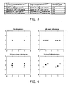
- Figure 4 shows how the constellation points shift from their ideal positions in the presence of either an amplitude gain, a phase shift or both, i.e. IQ phase and amplitude imbalances, but without any (random) phase noise.
- a phase shift of 20 degrees and/or an amplitude shift of 3dB is shown, but it will be understood that the actual phase and amplitude shifts may be any of a wide variety of magnitudes, in a given transmit chain.
- the ideal roots in the constellation are shown in Figure 4a , which represents the channel and data constellation absent any distortion in the transmit chain.
- +/-D1, +/-D2 and +/-D3 collapse onto the same two locations, +1 and -1.
- the true EVM can be estimated as follows.
- the data constellations will be shifted to one of a finite, known number of positions, for all transmitted data (in accordance with Equation 1 and Fig. 3 ).
- this is six locations +/-D1, +/-D2, and +/-D3 ( Fig. 3 ), but for different modulating techniques, other numbers of systematically shifted root locations will exist.
- Equation 1 and Fig. 3 allows a knowledge of the number of such shifted roots that will exist.
- the measured output constellations can be used to determine a true EVM. This is because each received data point will be located near to, but not actually at, one of the six possible locations in the constellation diagram of Figure 4 , and it is known to which one of the (in this case) six locations each data point will be shifted, because of Equation 1 and Figure 3 .
- the distance between each received data point and the possible location in the constellation diagram is a result purely of the random shifts in the transmit-receive chain and is thus representative of a true error vector. This feature enables a statistical analysis to be carried out even though at this stage the location of the finite number of roots in the constellation diagram is not known.
- each of the points in the constellation is allocated to its associated "ideal" location, that is, the location in the constellation diagram due only to IQ imbalance.
- this is one of -D1, -D2, -D3, +D1, +D2 or +D3.
- Allocation takes place on the basis of Equation 1 and Figure 3 , that is, although it is not yet known precisely where D1, D2 and D3 (and -D1, -D2, -D3) actually are located (in terms of co-ordinates in a constellation diagram), it is nevertheless known from Equation 1 and Figure 3 to which of these six points any given data point will be shifted.
- each data point has been allocated to a one of the six locations, a statistical analysis of each resulting "cluster" can be carried out.
- the spread of the data points in each cluster can be calculated, using standard statistical techniques. Typically, this will result in a standard deviation for each cluster being determined, although other parameters indicative of the spread of data points, such as the variance, may be calculated, of course.
- the true EVM of the transmitter chain can then be estimated by averaging the standard deviations of the data points in each cluster.
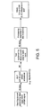
- the present invention is applied using a device test rig as shown in figure 5 .
- the Device Under Test (DUT) is positioned between test equipment configured to produce ideal baseband OFDM data and test equipment configured to down convert the resultant output of the DUT back into baseband, ready for processing by equipment which applies the above described process to determine the quality of the DUT.
- DUT Device Under Test
- a further advantageous consequence of such a statistical analysis of the data points in the constellation is that the mean of each of the six clusters may be used to estimate the actual location of the six points in the constellation diagram that result only from IQ imbalances and not also from phase errors.
- the mean positions determined represent the values +/-D1, +/-D2 and +/-D3, and this allows in turn the systematic gain and phase errors to be estimated, using equation 1.
- 128QAM for example, which is employed with the V.33 Modem Standard
- 128 points there are 128 points in a constellation diagram and one of these points is transmitted for every seven input bits.
- Each of these 128 points may separately be shifted due to systematic errors in the transmit/receive chain, leading to a constellation diagram analogous to Figure 4 but with a very large number of possible locations to which a data point may be shifted.
- the principles defined above may still be employed to allow determination of a true EVM, by carrying out a statistical analysis of the data points in each of the clusters to which any given data point is shifted.
Landscapes
- Engineering & Computer Science (AREA)
- Computer Networks & Wireless Communication (AREA)
- Signal Processing (AREA)
- Digital Transmission Methods That Use Modulated Carrier Waves (AREA)
Claims (6)
- Verfahren zum Bestimmen einer Fehlervektorgröße (EVM), die nur aus nicht-systematischen Effekten innerhalb einer Senderanordnung für ein drahtloses lokales Netz (WLAN) resultiert, die Schritte umfassend:(a) Zuführen einer Mehrzahl von Testsignalen zu einer Senderanordnung eines WLAN, wobei jedes Testsignal Daten enthält, die auf einen Unterträger eines orthogonal-frequenzbereich-multiplexierten (OFDM)-Signals moduliert sind, und eine Testsignalamplitude und -phase aufweist, wobei jeder Unterträger eine bestimmte Position innerhalb einer Bandbreite des OFDM-Signals aufweist, wobei die Mehrzahl der Testsignale wenigstens ein erstes Testsignal und ein zweites Testsignal umfasst, und wobei die Position des Unterträgers für das erste Testsignal und die Position des Unterträgers für das zweite Testsignal symmetrisch um den Mittelpunkt der Bandbreite des OFDM-Signals angeordnet sind;(b) Messen der Amplitude und der Phase der Testsignale, sobald sie durch die Senderanordnung gelaufen sind;(c) Zuordnen jeweils der gemessenen Amplituden- und Phasenwerte zu einer aus einer endlichen Mehrzahl von Datengruppen, wobei die Zuordnung der gemessenen Amplituden- und Phasenwerte, die dem ersten Testsignal entsprechen, zu einer Datengruppe auf der ersten Testsignalamplitude und -phase und der zweiten Testsignalamplitude und -phase beruht;(d) Bestimmen der Spanne der gemessenen Werte innerhalb jeder der Datengruppen; und(e) Berechnen der EVM, die nur aus nicht-systematischen Effekten innerhalb der Senderanordnung resultiert, auf der Grundlage der bestimmten Spanne der gemessenen Werte innerhalb der Datengruppen.
- Verfahren nach Anspruch 1, ferner umfassend:Bestimmen eines Mittelwertes der gemessenen Amplituden- und Phasenwerte innerhalb jeder der Datengruppen; undBerechnen der Größe eines systematischen Fehlervektors, der ein Ergebnis von systematischen Verschiebungen ist, die aufgrund von IQ-Ungleichgewichten in die Phase und in die Amplitude eines durch die Senderanordnung laufenden Signals eingeschleppt werden, aus dem Mittelwert.
- Verfahren nach Anspruch 1 oder Anspruch 2, wobei der Schritt des Bestimmens der Spanne der gemessenen Werte in jeder Datengruppe ferner umfasst:Berechnen der Standardabweichung der gemessenen Werte in jeder Datengruppe; undBerechnen der EVM auf der Grundlage eines Mittelwertes der berechneten Standardabweichungen.
- Verfahren nach Anspruch 3, wobei der Schritt des Berechnens der wahren EVM ferner umfasst:Bestimmen des Mittelwerts der berechneten Standardabweichungen für jede aus der endlichen Mehrzahl von Datengruppen.
- Verfahren nach Anspruch 2, wobei der Schritt des Bestimmens eines Mittelwertes der gemessenen Amplitude ferner das Berechnen der Position des Mittelwertes der Werte in jeder aus der endlichen Mehrzahl von Datengruppen umfasst.
- Verfahren nach irgendeinem der vorangehenden Ansprüche, wobei jedes Testsignal Testdaten enthält, die darauf unter Verwendung einer Technik aufmoduliert sind, die aus einer Liste ausgewählt ist, die umfasst:Binärphasenumtastung (BPSK), Quadraturamplitudenmodulation (QAM) und M-ary-Phasenumtastung (M-PSK),wobei die Anzahl der Datengruppen wenigstens zum Teil eine Folge der Datenmodulationsart ist.
Priority Applications (4)
| Application Number | Priority Date | Filing Date | Title |
|---|---|---|---|
| EP04253148A EP1601129B1 (de) | 2004-05-27 | 2004-05-27 | Verfahren zum Bestimmen der echten Fehlervektorgröße in einem drahtlosen lokalen Netzwerk |
| DE602004016295T DE602004016295D1 (de) | 2004-05-27 | 2004-05-27 | Verfahren zum Bestimmen der echten Fehlervektorgröße in einem drahtlosen lokalen Netzwerk |
| US11/597,604 US8116363B2 (en) | 2004-05-27 | 2005-05-27 | Method of determining true error vector magnitude in a wireless LAN |
| PCT/GB2005/002132 WO2005117322A1 (en) | 2004-05-27 | 2005-05-27 | Method of determining true error vector magnitude in a wireless lan |
Applications Claiming Priority (1)
| Application Number | Priority Date | Filing Date | Title |
|---|---|---|---|
| EP04253148A EP1601129B1 (de) | 2004-05-27 | 2004-05-27 | Verfahren zum Bestimmen der echten Fehlervektorgröße in einem drahtlosen lokalen Netzwerk |
Publications (2)
| Publication Number | Publication Date |
|---|---|
| EP1601129A1 EP1601129A1 (de) | 2005-11-30 |
| EP1601129B1 true EP1601129B1 (de) | 2008-09-03 |
Family
ID=34930342
Family Applications (1)
| Application Number | Title | Priority Date | Filing Date |
|---|---|---|---|
| EP04253148A Expired - Lifetime EP1601129B1 (de) | 2004-05-27 | 2004-05-27 | Verfahren zum Bestimmen der echten Fehlervektorgröße in einem drahtlosen lokalen Netzwerk |
Country Status (4)
| Country | Link |
|---|---|
| US (1) | US8116363B2 (de) |
| EP (1) | EP1601129B1 (de) |
| DE (1) | DE602004016295D1 (de) |
| WO (1) | WO2005117322A1 (de) |
Cited By (2)
| Publication number | Priority date | Publication date | Assignee | Title |
|---|---|---|---|---|
| CN103051585A (zh) * | 2012-07-27 | 2013-04-17 | 工业和信息化部通信计量中心 | 基于iq平面椭圆轨迹的数字调制参量计量方法与装置 |
| US20220166565A1 (en) * | 2017-04-28 | 2022-05-26 | Panasonic Intellectual Property Corporation Of America | Measurement apparatus and measurement method |
Families Citing this family (33)
| Publication number | Priority date | Publication date | Assignee | Title |
|---|---|---|---|---|
| US9094226B2 (en) | 2000-08-30 | 2015-07-28 | Broadcom Corporation | Home network system and method |
| JP2004525533A (ja) | 2000-08-30 | 2004-08-19 | ティアリス, インコーポレイテッド | 家庭用ネットワークシステムおよび方法 |
| US8724485B2 (en) | 2000-08-30 | 2014-05-13 | Broadcom Corporation | Home network system and method |
| US8090043B2 (en) * | 2006-11-20 | 2012-01-03 | Broadcom Corporation | Apparatus and methods for compensating for signal imbalance in a receiver |
| US7742495B2 (en) | 2006-11-20 | 2010-06-22 | Broadcom Corporation | System and method for retransmitting packets over a network of communication channels |
| US7782850B2 (en) | 2006-11-20 | 2010-08-24 | Broadcom Corporation | MAC to PHY interface apparatus and methods for transmission of packets through a communications network |
| US8345553B2 (en) | 2007-05-31 | 2013-01-01 | Broadcom Corporation | Apparatus and methods for reduction of transmission delay in a communication network |
| US8098770B2 (en) | 2008-05-06 | 2012-01-17 | Broadcom Corporation | Unbiased signal-to-noise ratio estimation for receiver having channel estimation error |
| CN101615992B (zh) * | 2008-06-23 | 2014-06-25 | 华为技术有限公司 | 多载波中业务的发送、接收方法、装置与发射机和接收机 |
| US9112717B2 (en) | 2008-07-31 | 2015-08-18 | Broadcom Corporation | Systems and methods for providing a MoCA power management strategy |
| US8213309B2 (en) | 2008-12-22 | 2012-07-03 | Broadcom Corporation | Systems and methods for reducing latency and reservation request overhead in a communications network |
| US8238227B2 (en) | 2008-12-22 | 2012-08-07 | Broadcom Corporation | Systems and methods for providing a MoCA improved performance for short burst packets |
| US8254413B2 (en) | 2008-12-22 | 2012-08-28 | Broadcom Corporation | Systems and methods for physical layer (“PHY”) concatenation in a multimedia over coax alliance network |
| US8553547B2 (en) | 2009-03-30 | 2013-10-08 | Broadcom Corporation | Systems and methods for retransmitting packets over a network of communication channels |
| US20100254278A1 (en) * | 2009-04-07 | 2010-10-07 | Broadcom Corporation | Assessment in an information network |
| US8730798B2 (en) | 2009-05-05 | 2014-05-20 | Broadcom Corporation | Transmitter channel throughput in an information network |
| US8867355B2 (en) * | 2009-07-14 | 2014-10-21 | Broadcom Corporation | MoCA multicast handling |
| US8942250B2 (en) | 2009-10-07 | 2015-01-27 | Broadcom Corporation | Systems and methods for providing service (“SRV”) node selection |
| US8611327B2 (en) | 2010-02-22 | 2013-12-17 | Broadcom Corporation | Method and apparatus for policing a QoS flow in a MoCA 2.0 network |
| US8514860B2 (en) | 2010-02-23 | 2013-08-20 | Broadcom Corporation | Systems and methods for implementing a high throughput mode for a MoCA device |
| JP2012095120A (ja) * | 2010-10-27 | 2012-05-17 | Advantest Corp | 測定装置、測定方法およびプログラム |
| US8837635B2 (en) * | 2011-06-08 | 2014-09-16 | Broadcom Corporation | Controlling a transmit path based on monitored error vector magnitude (EVM) performance |
| US8983395B2 (en) * | 2011-12-12 | 2015-03-17 | Apple Inc. | Methods and apparatus for testing radio-frequency power amplifier performance |
| US10331716B2 (en) * | 2013-12-17 | 2019-06-25 | International Business Machines Corporation | Data spreading on charts |
| US9100115B1 (en) | 2014-03-28 | 2015-08-04 | Freescale Semiconductor, Inc. | Processor unit for determining a quality indicator of a communication channel and a method thereof |
| US10057020B2 (en) * | 2015-11-19 | 2018-08-21 | Tektronix, Inc. | Joint estimation of coefficients for skew, gain imbalance and channel response for signal sources |
| US9893819B1 (en) * | 2017-01-26 | 2018-02-13 | Keysight Technologies, Inc. | Determining far field error vector magnitude (EVM) of a device under test over the air (OTA) |
| CN109067677B (zh) * | 2018-08-31 | 2020-10-30 | 中国人民解放军63686部队 | 一种基于高斯白噪声的可调evm矢量信号产生方法 |
| US10756829B1 (en) * | 2019-12-03 | 2020-08-25 | Teradyne, Inc. | Determining error vector magnitude using cross-correlation |
| US11646836B2 (en) | 2021-02-19 | 2023-05-09 | Keysight Technologies, Inc. | System and method of coherent averaging of repetitive signals for measurement |
| CN114372436B (zh) * | 2022-01-07 | 2024-04-05 | 西安海云物联科技有限公司 | 一种基于WiFi6 PA动态EVM的仿真设计测试方法 |
| CN115102646B (zh) * | 2022-07-26 | 2022-11-11 | 中国电力科学研究院有限公司 | 一种基于ofdm系统的非理想接收机evm测试补偿装置及方法 |
| CN115913868B (zh) * | 2022-11-25 | 2024-07-26 | 中科南京移动通信与计算创新研究院 | 一种基于聚类的矢量调制信号分析方法及其系统 |
Family Cites Families (11)
| Publication number | Priority date | Publication date | Assignee | Title |
|---|---|---|---|---|
| US6334219B1 (en) * | 1994-09-26 | 2001-12-25 | Adc Telecommunications Inc. | Channel selection for a hybrid fiber coax network |
| US6904110B2 (en) * | 1997-07-31 | 2005-06-07 | Francois Trans | Channel equalization system and method |
| EP0905940A3 (de) * | 1997-09-30 | 2001-05-16 | Lucent Technologies Inc. | Rückschleiftest mit Fehlervektoranalyse |
| CA2260336A1 (en) * | 1999-02-15 | 2000-08-15 | Robert Inkol | Modulation recognition system |
| EP1154580B1 (de) * | 2000-05-09 | 2006-10-11 | Alcatel | Verfahren zur Steuerung des Senders in einem Funksendeempfänger und der entsprechende Funksendeempfänger |
| US7142609B2 (en) * | 2000-11-29 | 2006-11-28 | Sunrise Telecom Incorporated | Method and apparatus for detecting and quantifying impairments in QAM signals |
| US20030129943A1 (en) * | 2001-12-18 | 2003-07-10 | Yunsang Park | Apparatus and method for link adaptation of packet data service on satellite systems |
| US7248625B2 (en) * | 2002-09-05 | 2007-07-24 | Silicon Storage Technology, Inc. | Compensation of I-Q imbalance in digital transceivers |
| EP1445906B1 (de) * | 2002-12-09 | 2006-05-31 | Rohde & Schwarz GmbH & Co. KG | Verfahren und Vorrichtung zum Analysieren eines OFDM-Signals |
| US7627055B2 (en) * | 2003-02-27 | 2009-12-01 | Nokia Corporation | Error adjustment in direct conversion architectures |
| US6933868B1 (en) * | 2004-03-02 | 2005-08-23 | Texas Instruments Incorporated | Testing of mixed signal integrated circuits generating analog signals from digital data elements |
-
2004
- 2004-05-27 DE DE602004016295T patent/DE602004016295D1/de not_active Expired - Lifetime
- 2004-05-27 EP EP04253148A patent/EP1601129B1/de not_active Expired - Lifetime
-
2005
- 2005-05-27 WO PCT/GB2005/002132 patent/WO2005117322A1/en active Application Filing
- 2005-05-27 US US11/597,604 patent/US8116363B2/en not_active Expired - Fee Related
Cited By (2)
| Publication number | Priority date | Publication date | Assignee | Title |
|---|---|---|---|---|
| CN103051585A (zh) * | 2012-07-27 | 2013-04-17 | 工业和信息化部通信计量中心 | 基于iq平面椭圆轨迹的数字调制参量计量方法与装置 |
| US20220166565A1 (en) * | 2017-04-28 | 2022-05-26 | Panasonic Intellectual Property Corporation Of America | Measurement apparatus and measurement method |
Also Published As
| Publication number | Publication date |
|---|---|
| US20090316589A1 (en) | 2009-12-24 |
| US8116363B2 (en) | 2012-02-14 |
| WO2005117322A1 (en) | 2005-12-08 |
| DE602004016295D1 (de) | 2008-10-16 |
| EP1601129A1 (de) | 2005-11-30 |
Similar Documents
| Publication | Publication Date | Title |
|---|---|---|
| EP1601129B1 (de) | Verfahren zum Bestimmen der echten Fehlervektorgröße in einem drahtlosen lokalen Netzwerk | |
| EP1021898B1 (de) | Signalisierungsübertragung durch phasendrehungstechniken in ein digitales kommunikationssystem | |
| US6934340B1 (en) | Adaptive control system for interference rejections in a wireless communications system | |
| US7016425B1 (en) | Quasi-differential modulation/demodulation method for multi-amplitude digital modulated signals and OFDM system | |
| US20050094613A1 (en) | Apparatus and method for transmitting/receiving a pilot signal for distinguishing a base station in a communication system using an OFDM scheme | |
| US7184714B1 (en) | Frequency domain estimation of IQ imbalance in a wireless OFDM direct conversion receiver using loopback connection | |
| US7274750B1 (en) | Gain and phase imbalance compensation for OFDM systems | |
| CN101807980A (zh) | 用于生成发送数据的帧的发送器的方法及发送器 | |
| EP1453261B1 (de) | Verfahren zur Kanalschätzung in einem mobilen Kommunikationssystem | |
| CN103124249B (zh) | 无导频的载波跟踪 | |
| CN102387099A (zh) | 认知无线系统中基于加性高斯白噪声信道数据辅助通信信号的信噪比误差矢量幅值估计方法 | |
| CN105610760B (zh) | 无线综测仪对单载波qpsk信号iq不平衡的检测方法 | |
| US7764712B2 (en) | Radio transmitting apparatus, radio receiving apparatus, radio transmitting method and radio receiving method | |
| US7760827B2 (en) | Method and apparatus for improving recovery performance of time windowed signals | |
| GB2510718A (en) | Method for indicating stealing in a digital mobile radio communications system | |
| WO2000003523A1 (en) | Data transmission method and radio system | |
| KR100760793B1 (ko) | 동기 수신기에서의 직교 및 이득 에러의 정정 | |
| CN109257311A (zh) | 确定误差矢量幅度的方法及系统 | |
| CN113794661A (zh) | 一种基于相位噪声优化接收性能的方法及系统 | |
| US4949356A (en) | PCM receiver with lock state control | |
| Bairwa et al. | BER Performance of OFDM System over AWGN channel with Different Modulation Schemes | |
| US6597751B1 (en) | Method of displaying signals in the presence of inter symbol interference | |
| CN115102646B (zh) | 一种基于ofdm系统的非理想接收机evm测试补偿装置及方法 | |
| Qi et al. | iDeepRx Enabled 100 Gb/s DFT-s-OFDM Data Transmission Over 220 GHz Testbed | |
| CN116405361B (zh) | 公共相位误差的补偿方法、装置、电子设备及计算机程序 |
Legal Events
| Date | Code | Title | Description |
|---|---|---|---|
| PUAI | Public reference made under article 153(3) epc to a published international application that has entered the european phase |
Free format text: ORIGINAL CODE: 0009012 |
|
| AK | Designated contracting states |
Kind code of ref document: A1 Designated state(s): AT BE BG CH CY CZ DE DK EE ES FI FR GB GR HU IE IT LI LU MC NL PL PT RO SE SI SK TR |
|
| AX | Request for extension of the european patent |
Extension state: AL HR LT LV MK |
|
| 17P | Request for examination filed |
Effective date: 20060529 |
|
| AKX | Designation fees paid |
Designated state(s): DE FR GB IT |
|
| 17Q | First examination report despatched |
Effective date: 20061106 |
|
| GRAP | Despatch of communication of intention to grant a patent |
Free format text: ORIGINAL CODE: EPIDOSNIGR1 |
|
| GRAS | Grant fee paid |
Free format text: ORIGINAL CODE: EPIDOSNIGR3 |
|
| GRAA | (expected) grant |
Free format text: ORIGINAL CODE: 0009210 |
|
| AK | Designated contracting states |
Kind code of ref document: B1 Designated state(s): DE FR GB IT |
|
| REG | Reference to a national code |
Ref country code: GB Ref legal event code: FG4D |
|
| REF | Corresponds to: |
Ref document number: 602004016295 Country of ref document: DE Date of ref document: 20081016 Kind code of ref document: P |
|
| PLBE | No opposition filed within time limit |
Free format text: ORIGINAL CODE: 0009261 |
|
| STAA | Information on the status of an ep patent application or granted ep patent |
Free format text: STATUS: NO OPPOSITION FILED WITHIN TIME LIMIT |
|
| 26N | No opposition filed |
Effective date: 20090604 |
|
| REG | Reference to a national code |
Ref country code: FR Ref legal event code: PLFP Year of fee payment: 13 |
|
| PGFP | Annual fee paid to national office [announced via postgrant information from national office to epo] |
Ref country code: GB Payment date: 20160527 Year of fee payment: 13 Ref country code: DE Payment date: 20160527 Year of fee payment: 13 |
|
| PGFP | Annual fee paid to national office [announced via postgrant information from national office to epo] |
Ref country code: FR Payment date: 20160530 Year of fee payment: 13 Ref country code: IT Payment date: 20160520 Year of fee payment: 13 |
|
| REG | Reference to a national code |
Ref country code: DE Ref legal event code: R119 Ref document number: 602004016295 Country of ref document: DE |
|
| GBPC | Gb: european patent ceased through non-payment of renewal fee |
Effective date: 20170527 |
|
| REG | Reference to a national code |
Ref country code: FR Ref legal event code: ST Effective date: 20180131 |
|
| PG25 | Lapsed in a contracting state [announced via postgrant information from national office to epo] |
Ref country code: GB Free format text: LAPSE BECAUSE OF NON-PAYMENT OF DUE FEES Effective date: 20170527 Ref country code: DE Free format text: LAPSE BECAUSE OF NON-PAYMENT OF DUE FEES Effective date: 20171201 |
|
| PG25 | Lapsed in a contracting state [announced via postgrant information from national office to epo] |
Ref country code: IT Free format text: LAPSE BECAUSE OF NON-PAYMENT OF DUE FEES Effective date: 20170527 Ref country code: FR Free format text: LAPSE BECAUSE OF NON-PAYMENT OF DUE FEES Effective date: 20170531 |