EP1601129B1 - Method of determining true error vector magnitude in a wireless lan - Google Patents
Method of determining true error vector magnitude in a wireless lan Download PDFInfo
- Publication number
- EP1601129B1 EP1601129B1 EP04253148A EP04253148A EP1601129B1 EP 1601129 B1 EP1601129 B1 EP 1601129B1 EP 04253148 A EP04253148 A EP 04253148A EP 04253148 A EP04253148 A EP 04253148A EP 1601129 B1 EP1601129 B1 EP 1601129B1
- Authority
- EP
- European Patent Office
- Prior art keywords
- phase
- amplitude
- data
- test signal
- test
- Prior art date
- Legal status (The legal status is an assumption and is not a legal conclusion. Google has not performed a legal analysis and makes no representation as to the accuracy of the status listed.)
- Expired - Fee Related
Links
Images

Classifications
-
- H—ELECTRICITY
- H04—ELECTRIC COMMUNICATION TECHNIQUE
- H04L—TRANSMISSION OF DIGITAL INFORMATION, e.g. TELEGRAPHIC COMMUNICATION
- H04L27/00—Modulated-carrier systems
- H04L27/32—Carrier systems characterised by combinations of two or more of the types covered by groups H04L27/02, H04L27/10, H04L27/18 or H04L27/26
- H04L27/34—Amplitude- and phase-modulated carrier systems, e.g. quadrature-amplitude modulated carrier systems
- H04L27/36—Modulator circuits; Transmitter circuits
- H04L27/362—Modulation using more than one carrier, e.g. with quadrature carriers, separately amplitude modulated
- H04L27/364—Arrangements for overcoming imperfections in the modulator, e.g. quadrature error or unbalanced I and Q levels
-
- H—ELECTRICITY
- H04—ELECTRIC COMMUNICATION TECHNIQUE
- H04L—TRANSMISSION OF DIGITAL INFORMATION, e.g. TELEGRAPHIC COMMUNICATION
- H04L27/00—Modulated-carrier systems
- H04L27/26—Systems using multi-frequency codes
- H04L27/2601—Multicarrier modulation systems
Landscapes
- Engineering & Computer Science (AREA)
- Computer Networks & Wireless Communication (AREA)
- Signal Processing (AREA)
- Digital Transmission Methods That Use Modulated Carrier Waves (AREA)
Description
- The present invention relates to a method of determining a True Error Vector Magnitude (EVM) in a wireless Local Area Network (WLAN).
- Modern high speed wireless Local Area Networks (WLANs) are comprised of a number of individual devices. These can be either clients or access points, and they communicate with each other via wireless links. In order to use these wireless links, each device must have both a transmitter and a receiver. Furthermore, to achieve optimal performance, the operating characteristics of the transmitting/receiving circuitry must be known. This requires the testing of each transmitter (and receiver) component prior to incorporation into a final WLAN product.
- The clients and access points that make up a WLAN communicate with the other clients or access points over the wireless links using one of the many standardized protocols that have been developed for use in WLANs. Some of these protocols, such as 802.11 a and g, make use of an OFDM modulation technique to encode the data to be transmitted onto a plurality of sub-carriers to convey the information to the receiver. Each sub-carrier is at a separate frequency that is orthogonal to, and equally spaced from, the other sub-carrier frequencies. An orthogonal frequency set is such that all frequencies other than the wanted frequency pass through zero at the wanted frequency. This ensures that the wanted frequency can be separated without the need for individual subband filters. It is the amplitude and phase of these individual sub-carriers which determine the data being carried by them.
- In WLAN systems according to the 802.11 a or g specifications, there are 52 individual sub-carriers, normally identified as -26 to -1 and +1 to+ 26.
- In general, the data stream to be transmitted is split up into a plurality of data sub-streams, each sub-stream consisting of a first, lower data rate, and a second, higher data rate. The individual sub-streams are created by scrambling the original input data stream to prevent long runs of 1's or 0's, and encoding the scrambled data using an error correcting code, for example Forward Error Correction (FEC). The coded data is then symbol and frequency interleaved to reduce individual susceptibility to so-called burst errors. The interleaved data stream is then mapped and modulated onto each of the frequency carriers using a suitable modulation technique. Depending on the requirements of the transmission link, different modulation techniques can be used. One such technique is Binary Phase Shift Keying (BPSK).
- When using BPSK, the sub-carrier amplitude is nominally set to 1 and the phase of the sub-carrier is set to either 0 or 180 degrees, depending on whether the data the sub-carrier is carrying is a 1 or 0. In such a modulation technique, each sub-carrier carries one bit of information.
- The amplitude and phase of the transmitted data are normally expressed as a set of one or more complex numbers in the form (N +iM), where N is the amplitude of the Quadrature part and M is the amplitude of the In-Phase part. The roots of these complex numbers are the points depicted on a Frequency Domain (IQ) diagram, as shown in
Figure 1 , which is usually referred to as a constellation in the frequency domain. - The complex numbers that result from BPSK modulation are therefore (1 + i0) and (-1 + i0) or +1 and -1, that is, the ideal constellation contains just two possible points. This is the case where each bit is encoded to one symbol.
- In real WLANs, data is encoded using more complex modulation techniques, such as Quadrature Amplitude Modulation (QAM) or Gaussian Minimum Shift Keying (GMSK), where there are more than two possible root locations, each corresponding to a particular symbol value, and each symbol equating to a set of data bits being sent per transmission time slot, therefore allowing more data to be sent, at the expense of more complex decoding being required.
- In systems such as these, where the amplitude and phase of the data can be expressed as a constellation diagram, if an ideal transmitter were to be used, sending its information across an ideal channel, the position of the roots would not change, and therefore the receiver could easily work out what data was being sent by the transmitter, and with no errors. However, real transmitters and channels warp the signal being sent, resulting in roots that are shifted from their ideal positions. The shifts can be seen as rotations about the origin of the IQ axes, or as movement along the length of the axes. These shifts are caused by gain and phase imbalances in the transmit chain, by random phase noise in the transmitter, and by the distortion due to the channel the data is sent over.
- In the presence of such shifts, the receiver can incorrectly decode a transmitted root location, because the shifts due to the non-ideal nature of the transmission can result in the roots being moved to (or near) the location of other, equally valid, root locations. These errors are exacerbated in systems with more closely spaced possible root locations, such as QAM. An example of such an erroneous root determination may be understood with reference to
Figures 2a and 2b . InFigure 2a , the idealized root of the locations of an arbitrary encoding technique are shown. InFigure 2b , the actual root locations are shown in solid line of which two are labelled, as 10 and 20. It will be noted that the actual constellation of root locations is rotated about the IQ axes relative to the idealized locations (shown inFigure 2b in faint). It will also be seen that theactual root locations different root locations - The measure of how far a root has moved from its actual, intended location, is called the Error Vector Magnitude (EVM). The measure of this movement as a result of the transmitter only is called the EVM of the transmitter. To allow accurate estimation of the error introduced by the channel, the EVM of the transmitter must be known.
- The total EVM of the transmitter is a result of the effects of phase noise, which is random in nature, and from the IQ phase and gain imbalances in the transmit hardware chain, which is systematic in nature.
- Since the IQ phase and gain imbalances are systematic in nature, they can be measured, then compensated for in the input signal by pre-distortion of the input signal. The true EVM due to only the random phase noise can then be found. It is this random effect of the phase noise that limits the capability of the transmitter, and thus it is important to test the transmitter for its true EVM to know its limitations or quality. Transmitter Device manufacturers can then remove substandard parts from their production lines.
- The procedure for measuring the true EVM of a transmitter that is currently employed first measures the effect of the systematic error introduced by the IQ phase and amplitude imbalances, then pre-distorts the input signal to counteract these errors. The true EVM due to the random phase noise alone is then measured. More specifically, the first test, to measure the IQ phase and amplitude imbalances, involves inputting a single, known frequency and amplitude test tone into both the I and Q inputs. The amplitude and phase offsets are then measured at the output using test equipment. Once these parameters are known, the input signal is then recalculated to pre-distort it to compensate for these errors. The true EVM is then measured in a second test by inputting a test pattern predistorted using the values obtained in the first test , measuring the output and comparing the input to the output. The procedure is thus relatively time-consuming, since it requires two separate tests to be carried out, with a recalculation step in between to take into account the results of the first test. Furthermore, this two step test with a recalculation in between must be carried out for each transmitter separately.
-
EP-A-0 905 940 relates to a method for determining an error vector in a CDMA system, by looping back the output of the transmitter into a receiver having an error vector processor. The error vector processor demodulates the received signal to obtain a received data stream, re-modulates the received data and gives the error vector as the difference between the received and re-modulated signals. -
US-A-2002/0090909 describes a method for determining the signal to noise ratio at the output of an OFDM system. - ETSI TS 100 910 is a technical specification for a digital cellular telecommunication system. It specifies a method for Error Vector Magnitude determination in a system based on CDMA.
- The present invention, against this background provides a method of determining an Error Vector Magnitude (EVM) resulting only from non-systematic effects according to
independent claim 1. - Using this technique, it is no longer necessary to correct for phase or amplitude imbalances, nor to know in advance what the actual imbalance is. Instead, the actual phase and amplitude is analysed, for example by a statistical analysis, using the fact that each of the measured data points is (or at least should be) clustered around one of a finite and known number of roots in the constellation diagram. This allows the true EVM, resulting only from random phase errors and the like, to be determined without first having to calculate and compensate for the systematic distortions resulting from IQ imbalances. As a result, measurement of the true EVM is faster and cheaper.
- The invention may be put into practice in a number of ways, and one preferred embodiment will now be described by way of example only and with reference to the accompanying drawings in which:
-
Fig. 1 shows a constellation diagram indicating the ideal locations of the roots in an IQ plot, for BPSK. -
Fig. 2 shows a constellation diagram indicating the ideal root locations of an arbitrary encoding technique; -
Fig. 2b shows the constellation diagram ofFigure 2a , onto which has been superimposed the shifted root locations as a result of IQ phase and amplitude imbalances; -
Fig. 3 shows a table indicating the six possible root locations (three positive and three negative) for a single BPSK symbol data constellation when shifted due to IQ phase and amplitude imbalances, both in the data and also in the channel information, and -
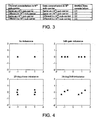
Figs. 4a, 4b, 4c and 4d show constellation diagrams depicting the ideal root locations, as well as the six root locations ofFig. 3 , in the presence of amplitude gain, phase shift and both, in a transmitter chain. -
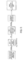
Figure 5 shows a schematic of a typical transmitter device test setup, in accordance with an embodiment of the present invention. - It can be shown that, in the presence of systematic transmit IQ phase and amplitude imbalances in the transmit chain, the roots of the constellation diagram for a Binary Phase Shift Keyed (BPSK) signal are shifted in the frequency domain to one of the following two possible new positions:


- Whether a point in a constellation is shifted to c1 or c2 is dependent on the value of the sub-carrier and its corresponding negative sub-carrier. For example, in BPSK, the constellation point represented by sub-carrier 26 is shifted dependent on the value of the sub-carrier -26. If the values in sub-carrier 26 and -26 are identical, then the constellation points are shifted to location c1. If the values in 26 and -26 are different, the constellation points are instead shifted to c2 in the IQ diagram.
- Distortion is present even when the signal is received and down-converted using an ideal receiver. In the real world, the signal is in fact down mixed to an Intermediate Frequency (IF) and then the final, complex down conversion of the IQ signals is carried out digitally.
- The digital down conversion of the IQ signals of an 802.11 a/g packet normally occurs using the following known demodulation processes. Firstly, the start of the packet or payload is found by synchronization with the packet preamble using a synchronizer. Next, the frequency offset between the transmitter and receiver is estimated, and a correction for that frequency offset is made. Then the channel is estimated, i.e. the effect of the channel on the IQ signals is calculated. Finally, the OFDM symbols are separated and the data recovered from them using the standard OFDM demodulation process, but taking into account the effect of the distortion due to the channel.
- During the course of this known demodulation process, it is assumed that the transmitter is behaving in an ideal fashion, and is not affecting the data in any way. However in reality, this is not the case. In particular, it is necessary for the receiver to know the distortion due to the transmitter, so that these effects can be taken into account when the channel is being estimated.
- Again in accordance with known procedures, the channel estimate for any given sub-carrier is found by sending a known training sequence, which results in a known sequence of BPSK constellations, from the transmitter to the receiver. The constellations actually received are then compared with the expected transmission constellations, which gives the necessary information on how the following data constellations can be expected to be modified by the channel in respect of this particular sub-carrier. This process is usually carried out on a regular basis, since the channel is not constant over time. For example, channel estimation can be carried out once per frame.
- As discussed above, the constellation corresponding to the channel will be shifted to one of two positions, c1 or c2, due to the IQ phase and amplitude imbalances, depending on the data carried in the sub-carrier to which the channel applies, and its negative sub-carrier. The data constellations following the channel estimate constellations are affected by the transmitter and channel in the same way, i.e. move to a first position c1 if the data of the relevant positive and negative sub-carriers are the same, or move to a second position c2 if the data on the relevant positive and negative sub-carriers are not the same. These effects are associative, so that the measured output constellation can be shifted to one of three positions for each of the possible data symbols, namely c1.c1=d1, c1.c2=c2.c1=d2, and c2.c2=d3. The various combinations are set out in the table of
Figure 3 . -
Figure 4 shows how the constellation points shift from their ideal positions in the presence of either an amplitude gain, a phase shift or both, i.e. IQ phase and amplitude imbalances, but without any (random) phase noise. For the sake of illustration only, a phase shift of 20 degrees and/or an amplitude shift of 3dB is shown, but it will be understood that the actual phase and amplitude shifts may be any of a wide variety of magnitudes, in a given transmit chain. The ideal roots in the constellation are shown inFigure 4a , which represents the channel and data constellation absent any distortion in the transmit chain. In accordance withFig. 3 andEquation 1, +/-D1, +/-D2 and +/-D3 collapse onto the same two locations, +1 and -1. When there is only gain distortion (Fig. 4b ), the ideal roots +1 and -1 are moved to +D1, +D2 and +D3, and also -D1, -D2 and -D3, where in this example -D2 = -1 and +D2 = +1. For a phase only distortion (Fig. 4c ), the ideal roots +1 and -1 are shifted to different locations +D1', +D2 and +D3', and -D1', -D2 and -D3', where +D2 = +1 and -D2 = -1 again. Finally, as seen inFigure 4d , where there is both phase and gain distortion (the usual case in a real transmit chain), the two ideal roots are shifted to still other locations +D1", +D2 and +D3", -D1", -D2 and -D3", where +D2 = +1 and -D2 = -1 still, however, in this example. - True points in a constellation diagram for a real transmit chain having, say, the 20 degree and 3dB phase and amplitude shifts of
Fig. 4d , for example, will tend to be clustered around, but not actually at, one of the six points shown inFig. 4d . This is as a result of the additional random phase noise. Calculating the EVM by linking the real, measured points in the constellation diagram to the ideal roots would however then result in false, large values. - In accordance with the embodiment of the present invention, however, the true EVM can be estimated as follows. As explained above, it is actually known that the data constellations will be shifted to one of a finite, known number of positions, for all transmitted data (in accordance with
Equation 1 andFig. 3 ). For BPSK, this is six locations +/-D1, +/-D2, and +/-D3 (Fig. 3 ), but for different modulating techniques, other numbers of systematically shifted root locations will exist. Even though, at this stage, the actual position of each systematically shifted root in the constellation diagram is not known,Equation 1 andFig. 3 allows a knowledge of the number of such shifted roots that will exist. Using known training sequences that it is known will be shifted to all the possible locations in the constellation diagram (that is, training sequences using all the different combinations of the same and different data in the sub-carriers), the measured output constellations can be used to determine a true EVM. This is because each received data point will be located near to, but not actually at, one of the six possible locations in the constellation diagram ofFigure 4 , and it is known to which one of the (in this case) six locations each data point will be shifted, because ofEquation 1 andFigure 3 . The distance between each received data point and the possible location in the constellation diagram is a result purely of the random shifts in the transmit-receive chain and is thus representative of a true error vector. This feature enables a statistical analysis to be carried out even though at this stage the location of the finite number of roots in the constellation diagram is not known. - As a first step, each of the points in the constellation is allocated to its associated "ideal" location, that is, the location in the constellation diagram due only to IQ imbalance. In
Figure 4 , this is one of -D1, -D2, -D3, +D1, +D2 or +D3. Allocation takes place on the basis ofEquation 1 andFigure 3 , that is, although it is not yet known precisely where D1, D2 and D3 (and -D1, -D2, -D3) actually are located (in terms of co-ordinates in a constellation diagram), it is nevertheless known fromEquation 1 andFigure 3 to which of these six points any given data point will be shifted. - Once each data point has been allocated to a one of the six locations, a statistical analysis of each resulting "cluster" can be carried out. In particular, the spread of the data points in each cluster can be calculated, using standard statistical techniques. Typically, this will result in a standard deviation for each cluster being determined, although other parameters indicative of the spread of data points, such as the variance, may be calculated, of course. The true EVM of the transmitter chain can then be estimated by averaging the standard deviations of the data points in each cluster.
- The present invention is applied using a device test rig as shown in
figure 5 . The Device Under Test (DUT) is positioned between test equipment configured to produce ideal baseband OFDM data and test equipment configured to down convert the resultant output of the DUT back into baseband, ready for processing by equipment which applies the above described process to determine the quality of the DUT. - In order to obtain a reasonably accurate fit to a Gaussian model of the spread of data points in each cluster, it is desirable to ensure that a relatively significant sample size is employed, say, in excess of 1,000 data points.
- A further advantageous consequence of such a statistical analysis of the data points in the constellation is that the mean of each of the six clusters may be used to estimate the actual location of the six points in the constellation diagram that result only from IQ imbalances and not also from phase errors. The mean positions determined represent the values +/-D1, +/-D2 and +/-D3, and this allows in turn the systematic gain and phase errors to be estimated, using
equation 1. - Using this method, there is no need to correct for the imbalance due to the IQ phase and amplitude imbalances beforehand, in a separate test, and a true EVM can be produced in a single testing step. Also there is now no need for a recalculation of the input signal, to pre-distort the input to compensate for the IQ imbalances found in the earlier test. The test is therefore reduced in complexity, the amount of test equipment required and the time taken per test.
- Although the foregoing description of a preferred embodiment has described the procedure in terms of binary phase shift keying, it is to be understood that this is by way of example only, not least because the principles of the invention can most readily be understood when there are only two roots (+1 and -1) in a constellation diagram for that modulation procedure. In particular, various other forms of encoding, including but not limited to Binary Amplitude Shift Keying (BASK), Quadrature Amplitude Modulation (QAM), and M-ary Phase Shift Keying (M-PSK) may be employed instead, to modulate data onto a sub-channel of an OFDM signal. In the case of 128QAM, for example, which is employed with the V.33 Modem Standard, there are 128 points in a constellation diagram and one of these points is transmitted for every seven input bits. Each of these 128 points may separately be shifted due to systematic errors in the transmit/receive chain, leading to a constellation diagram analogous to
Figure 4 but with a very large number of possible locations to which a data point may be shifted. Nevertheless, the principles defined above may still be employed to allow determination of a true EVM, by carrying out a statistical analysis of the data points in each of the clusters to which any given data point is shifted. - In general terms, where there are n possible "ideal" locations to which data may be shifted (that is, n locations in the absence of random phase noise), provided that it is known to which of the n "ideal" locations any given data point will be shifted, a mean and standard deviation of the cluster at each location can still be calculated, and from that, the values of the true EVM (an average of +/-D1, +/-D2, +/-D3...+/-D(n/2)) can be estimated. The intermediate steps (and in particular pre-distortion of the transmit signal) are accordingly still avoided, even with a potentially very large number of ideal locations, n, in a constellation diagram.
Claims (6)
- A method of determining an Error Vector Magnitude (EVM) resulting only from non-systematic effects within a transmitter arrangement for a wireless local area network (WLAN), comprising the steps of:(a) supplying a plurality of test signals to a transmitter arrangement of a WLAN, each test signal including data modulated onto a sub-carrier of an Orthogonal Frequency Division Multiplexed (OFDM) signal and having a test signal amplitude and phase, each sub-carrier having a predetermined position within a bandwidth of the OFDM signal, the plurality of test signals comprising at least a first test signal and a second test signal, and wherein the position of the sub-carrier for the first test signal and the position of the sub-carrier for the second test signal are symmetrically arranged about the mid-point of the bandwidth of the OFDM signal;(b) measuring the amplitude and phase of the test signals once they have passed through the transmitter arrangement;(c) allocating each of the measured amplitude and phase values to one of a finite plurality of data groups, wherein the allocation to a data group of the measured amplitude and phase values corresponding to the first test signal is based on the first test signal amplitude and phase and the second test signal amplitude and phase;(d) determining the spread in the said measured values, within each of the data groups: and(e) calculating the EVM resulting only from non-systematic effects within the transmitter arrangement, based upon the determined spread of the measured values within the data groups.
- The method of claim 1, further comprising:determining an average of the measured amplitude and phase values within each of the data groups; andcalculating, from the said average, the magnitude of a systematic error vector which is a result of systematic shifts introduced into the phase and amplitude of a signal passing through the transmitter arrangement, due to IQ imbalances.
- The method of claim 1 or claim 2, wherein the step of determining the spread in the said measured values in each data group further comprises:calculating the standard deviation of the said measured values in each data group; andcalculating the EVM based upon an average of the calculated standard deviations.
- The method of claim 3, wherein the step of calculating the true EVM further comprises:determining the mean of the calculated standard deviations for each of the finite plurality of the data groups.
- The method of claim 2, wherein the step of determining an average of the measured amplitude further comprises calculating the position of the mean of the values in each of the finite plurality of data groups.
- The method of any preceding claim, wherein each test signal includes test data modulated onto it using a technique selected from the list comprising:Binary Phase Shift Keying (BPSK); Quadrature Amplitude Modulation (QAM), and M-ary Phase Shift Keying (M-PSK),and wherein the number of data groups is at least in part a consequence of the manner of data modulation.
Priority Applications (4)
| Application Number | Priority Date | Filing Date | Title |
|---|---|---|---|
| EP04253148A EP1601129B1 (en) | 2004-05-27 | 2004-05-27 | Method of determining true error vector magnitude in a wireless lan |
| DE602004016295T DE602004016295D1 (en) | 2004-05-27 | 2004-05-27 | A method for determining true error vector size in a wireless local area network |
| PCT/GB2005/002132 WO2005117322A1 (en) | 2004-05-27 | 2005-05-27 | Method of determining true error vector magnitude in a wireless lan |
| US11/597,604 US8116363B2 (en) | 2004-05-27 | 2005-05-27 | Method of determining true error vector magnitude in a wireless LAN |
Applications Claiming Priority (1)
| Application Number | Priority Date | Filing Date | Title |
|---|---|---|---|
| EP04253148A EP1601129B1 (en) | 2004-05-27 | 2004-05-27 | Method of determining true error vector magnitude in a wireless lan |
Publications (2)
| Publication Number | Publication Date |
|---|---|
| EP1601129A1 EP1601129A1 (en) | 2005-11-30 |
| EP1601129B1 true EP1601129B1 (en) | 2008-09-03 |
Family
ID=34930342
Family Applications (1)
| Application Number | Title | Priority Date | Filing Date |
|---|---|---|---|
| EP04253148A Expired - Fee Related EP1601129B1 (en) | 2004-05-27 | 2004-05-27 | Method of determining true error vector magnitude in a wireless lan |
Country Status (4)
| Country | Link |
|---|---|
| US (1) | US8116363B2 (en) |
| EP (1) | EP1601129B1 (en) |
| DE (1) | DE602004016295D1 (en) |
| WO (1) | WO2005117322A1 (en) |
Cited By (2)
| Publication number | Priority date | Publication date | Assignee | Title |
|---|---|---|---|---|
| CN103051585A (en) * | 2012-07-27 | 2013-04-17 | 工业和信息化部通信计量中心 | Metering method and device for digital modulation parameter based on IQ (Intelligence Quotient) plane elliptical orbit |
| US20220166565A1 (en) * | 2017-04-28 | 2022-05-26 | Panasonic Intellectual Property Corporation Of America | Measurement apparatus and measurement method |
Families Citing this family (32)
| Publication number | Priority date | Publication date | Assignee | Title |
|---|---|---|---|---|
| US9094226B2 (en) | 2000-08-30 | 2015-07-28 | Broadcom Corporation | Home network system and method |
| US8724485B2 (en) | 2000-08-30 | 2014-05-13 | Broadcom Corporation | Home network system and method |
| ATE485650T1 (en) | 2000-08-30 | 2010-11-15 | Tmt Coaxial Networks Inc | METHOD AND SYSTEM FOR A HOME NETWORK |
| US7782850B2 (en) | 2006-11-20 | 2010-08-24 | Broadcom Corporation | MAC to PHY interface apparatus and methods for transmission of packets through a communications network |
| US7742495B2 (en) | 2006-11-20 | 2010-06-22 | Broadcom Corporation | System and method for retransmitting packets over a network of communication channels |
| US8090043B2 (en) * | 2006-11-20 | 2012-01-03 | Broadcom Corporation | Apparatus and methods for compensating for signal imbalance in a receiver |
| US8345553B2 (en) | 2007-05-31 | 2013-01-01 | Broadcom Corporation | Apparatus and methods for reduction of transmission delay in a communication network |
| US8098770B2 (en) | 2008-05-06 | 2012-01-17 | Broadcom Corporation | Unbiased signal-to-noise ratio estimation for receiver having channel estimation error |
| CN101615992B (en) * | 2008-06-23 | 2014-06-25 | 华为技术有限公司 | Device and method for transmitting and receiving service in multiple carriers, as well as transmitter and receiver |
| US9112717B2 (en) | 2008-07-31 | 2015-08-18 | Broadcom Corporation | Systems and methods for providing a MoCA power management strategy |
| US8213309B2 (en) | 2008-12-22 | 2012-07-03 | Broadcom Corporation | Systems and methods for reducing latency and reservation request overhead in a communications network |
| US8254413B2 (en) | 2008-12-22 | 2012-08-28 | Broadcom Corporation | Systems and methods for physical layer (“PHY”) concatenation in a multimedia over coax alliance network |
| US8238227B2 (en) | 2008-12-22 | 2012-08-07 | Broadcom Corporation | Systems and methods for providing a MoCA improved performance for short burst packets |
| US8553547B2 (en) | 2009-03-30 | 2013-10-08 | Broadcom Corporation | Systems and methods for retransmitting packets over a network of communication channels |
| US20100254278A1 (en) | 2009-04-07 | 2010-10-07 | Broadcom Corporation | Assessment in an information network |
| US8730798B2 (en) | 2009-05-05 | 2014-05-20 | Broadcom Corporation | Transmitter channel throughput in an information network |
| US8867355B2 (en) * | 2009-07-14 | 2014-10-21 | Broadcom Corporation | MoCA multicast handling |
| US8942250B2 (en) | 2009-10-07 | 2015-01-27 | Broadcom Corporation | Systems and methods for providing service (“SRV”) node selection |
| US8611327B2 (en) | 2010-02-22 | 2013-12-17 | Broadcom Corporation | Method and apparatus for policing a QoS flow in a MoCA 2.0 network |
| US8514860B2 (en) | 2010-02-23 | 2013-08-20 | Broadcom Corporation | Systems and methods for implementing a high throughput mode for a MoCA device |
| JP2012095120A (en) * | 2010-10-27 | 2012-05-17 | Advantest Corp | Measuring apparatus, measuring method, and program |
| US8837635B2 (en) * | 2011-06-08 | 2014-09-16 | Broadcom Corporation | Controlling a transmit path based on monitored error vector magnitude (EVM) performance |
| US8983395B2 (en) * | 2011-12-12 | 2015-03-17 | Apple Inc. | Methods and apparatus for testing radio-frequency power amplifier performance |
| US10331716B2 (en) * | 2013-12-17 | 2019-06-25 | International Business Machines Corporation | Data spreading on charts |
| US9100115B1 (en) | 2014-03-28 | 2015-08-04 | Freescale Semiconductor, Inc. | Processor unit for determining a quality indicator of a communication channel and a method thereof |
| US10057020B2 (en) * | 2015-11-19 | 2018-08-21 | Tektronix, Inc. | Joint estimation of coefficients for skew, gain imbalance and channel response for signal sources |
| US9893819B1 (en) * | 2017-01-26 | 2018-02-13 | Keysight Technologies, Inc. | Determining far field error vector magnitude (EVM) of a device under test over the air (OTA) |
| CN109067677B (en) * | 2018-08-31 | 2020-10-30 | 中国人民解放军63686部队 | Adjustable EVM vector signal generation method based on Gaussian white noise |
| US10756829B1 (en) * | 2019-12-03 | 2020-08-25 | Teradyne, Inc. | Determining error vector magnitude using cross-correlation |
| US11646836B2 (en) | 2021-02-19 | 2023-05-09 | Keysight Technologies, Inc. | System and method of coherent averaging of repetitive signals for measurement |
| CN114372436B (en) * | 2022-01-07 | 2024-04-05 | 西安海云物联科技有限公司 | Simulation design test method based on WiFi6 PA dynamic EVM |
| CN115102646B (en) * | 2022-07-26 | 2022-11-11 | 中国电力科学研究院有限公司 | Non-ideal receiver EVM test compensation device and method based on OFDM system |
Family Cites Families (11)
| Publication number | Priority date | Publication date | Assignee | Title |
|---|---|---|---|---|
| US6334219B1 (en) * | 1994-09-26 | 2001-12-25 | Adc Telecommunications Inc. | Channel selection for a hybrid fiber coax network |
| US6904110B2 (en) * | 1997-07-31 | 2005-06-07 | Francois Trans | Channel equalization system and method |
| EP0905940A3 (en) * | 1997-09-30 | 2001-05-16 | Lucent Technologies Inc. | Loopback testing using error vector analysis |
| CA2260336A1 (en) * | 1999-02-15 | 2000-08-15 | Robert Inkol | Modulation recognition system |
| EP1154580B1 (en) * | 2000-05-09 | 2006-10-11 | Alcatel | A method for controlling the transmitter part of a radio transceiver and a corresponding radio transceiver |
| US7142609B2 (en) * | 2000-11-29 | 2006-11-28 | Sunrise Telecom Incorporated | Method and apparatus for detecting and quantifying impairments in QAM signals |
| US20030129943A1 (en) * | 2001-12-18 | 2003-07-10 | Yunsang Park | Apparatus and method for link adaptation of packet data service on satellite systems |
| US7248625B2 (en) * | 2002-09-05 | 2007-07-24 | Silicon Storage Technology, Inc. | Compensation of I-Q imbalance in digital transceivers |
| EP1445906B1 (en) * | 2002-12-09 | 2006-05-31 | Rohde & Schwarz GmbH & Co. KG | Method and device for analysing an OFDM signal |
| US7627055B2 (en) * | 2003-02-27 | 2009-12-01 | Nokia Corporation | Error adjustment in direct conversion architectures |
| US6933868B1 (en) * | 2004-03-02 | 2005-08-23 | Texas Instruments Incorporated | Testing of mixed signal integrated circuits generating analog signals from digital data elements |
-
2004
- 2004-05-27 EP EP04253148A patent/EP1601129B1/en not_active Expired - Fee Related
- 2004-05-27 DE DE602004016295T patent/DE602004016295D1/en active Active
-
2005
- 2005-05-27 WO PCT/GB2005/002132 patent/WO2005117322A1/en active Application Filing
- 2005-05-27 US US11/597,604 patent/US8116363B2/en not_active Expired - Fee Related
Cited By (2)
| Publication number | Priority date | Publication date | Assignee | Title |
|---|---|---|---|---|
| CN103051585A (en) * | 2012-07-27 | 2013-04-17 | 工业和信息化部通信计量中心 | Metering method and device for digital modulation parameter based on IQ (Intelligence Quotient) plane elliptical orbit |
| US20220166565A1 (en) * | 2017-04-28 | 2022-05-26 | Panasonic Intellectual Property Corporation Of America | Measurement apparatus and measurement method |
Also Published As
| Publication number | Publication date |
|---|---|
| US8116363B2 (en) | 2012-02-14 |
| WO2005117322A1 (en) | 2005-12-08 |
| DE602004016295D1 (en) | 2008-10-16 |
| US20090316589A1 (en) | 2009-12-24 |
| EP1601129A1 (en) | 2005-11-30 |
Similar Documents
| Publication | Publication Date | Title |
|---|---|---|
| EP1601129B1 (en) | Method of determining true error vector magnitude in a wireless lan | |
| EP1021898B1 (en) | Signalling transmission using phase rotation techniques in a digital communications system | |
| US7369531B2 (en) | Apparatus and method for transmitting/receiving a pilot signal for distinguishing a base station in a communication system using an OFDM scheme | |
| US6424678B1 (en) | Scalable pattern methodology for multi-carrier communication systems | |
| US6934340B1 (en) | Adaptive control system for interference rejections in a wireless communications system | |
| US7016425B1 (en) | Quasi-differential modulation/demodulation method for multi-amplitude digital modulated signals and OFDM system | |
| US7129802B2 (en) | Method for estimating a carrier leak, an estimator and modulation system provided with automatic control of a carrier using said system | |
| US7184714B1 (en) | Frequency domain estimation of IQ imbalance in a wireless OFDM direct conversion receiver using loopback connection | |
| US7274750B1 (en) | Gain and phase imbalance compensation for OFDM systems | |
| CN101807980A (en) | Apparatus for transmitting and receiving data to provide high-speed data comunication and method thereof | |
| EP1453261B1 (en) | Channel estimation method for a mobile communication system | |
| CN103124249B (en) | Carrier tracking without pilots | |
| CN102387099A (en) | Method for estimating error vector amplitude of SNR (signal-to-noise ratio) of AWGN (additive white Gaussian noise) channel based data-aided communication signal in cognitive radio system | |
| US7764712B2 (en) | Radio transmitting apparatus, radio receiving apparatus, radio transmitting method and radio receiving method | |
| US7760827B2 (en) | Method and apparatus for improving recovery performance of time windowed signals | |
| WO2006027604A1 (en) | Frequency error correction by using remodulation | |
| KR100736197B1 (en) | Wireless communication method and apparatus for performing post-detection constellation correction | |
| GB2510718A (en) | Method for indicating stealing in a digital mobile radio communications system | |
| CN109257311B (en) | Method and system for determining error vector magnitude | |
| CN113794661A (en) | Method and system for optimizing receiving performance based on phase noise | |
| US4949356A (en) | PCM receiver with lock state control | |
| EP1130866B1 (en) | Correction of quadrature and gain errors in homodyne receivers | |
| US6597751B1 (en) | Method of displaying signals in the presence of inter symbol interference | |
| KR20030082103A (en) | A Baseband Modem Apparatus Suitable for Bluetooth System by using OFDM Modem | |
| CN115102646A (en) | Non-ideal receiver EVM test compensation device and method based on OFDM system |
Legal Events
| Date | Code | Title | Description |
|---|---|---|---|
| PUAI | Public reference made under article 153(3) epc to a published international application that has entered the european phase |
Free format text: ORIGINAL CODE: 0009012 |
|
| AK | Designated contracting states |
Kind code of ref document: A1 Designated state(s): AT BE BG CH CY CZ DE DK EE ES FI FR GB GR HU IE IT LI LU MC NL PL PT RO SE SI SK TR |
|
| AX | Request for extension of the european patent |
Extension state: AL HR LT LV MK |
|
| 17P | Request for examination filed |
Effective date: 20060529 |
|
| AKX | Designation fees paid |
Designated state(s): DE FR GB IT |
|
| 17Q | First examination report despatched |
Effective date: 20061106 |
|
| GRAP | Despatch of communication of intention to grant a patent |
Free format text: ORIGINAL CODE: EPIDOSNIGR1 |
|
| GRAS | Grant fee paid |
Free format text: ORIGINAL CODE: EPIDOSNIGR3 |
|
| GRAA | (expected) grant |
Free format text: ORIGINAL CODE: 0009210 |
|
| AK | Designated contracting states |
Kind code of ref document: B1 Designated state(s): DE FR GB IT |
|
| REG | Reference to a national code |
Ref country code: GB Ref legal event code: FG4D |
|
| REF | Corresponds to: |
Ref document number: 602004016295 Country of ref document: DE Date of ref document: 20081016 Kind code of ref document: P |
|
| PLBE | No opposition filed within time limit |
Free format text: ORIGINAL CODE: 0009261 |
|
| STAA | Information on the status of an ep patent application or granted ep patent |
Free format text: STATUS: NO OPPOSITION FILED WITHIN TIME LIMIT |
|
| 26N | No opposition filed |
Effective date: 20090604 |
|
| REG | Reference to a national code |
Ref country code: FR Ref legal event code: PLFP Year of fee payment: 13 |
|
| PGFP | Annual fee paid to national office [announced via postgrant information from national office to epo] |
Ref country code: GB Payment date: 20160527 Year of fee payment: 13 Ref country code: DE Payment date: 20160527 Year of fee payment: 13 |
|
| PGFP | Annual fee paid to national office [announced via postgrant information from national office to epo] |
Ref country code: FR Payment date: 20160530 Year of fee payment: 13 Ref country code: IT Payment date: 20160520 Year of fee payment: 13 |
|
| REG | Reference to a national code |
Ref country code: DE Ref legal event code: R119 Ref document number: 602004016295 Country of ref document: DE |
|
| GBPC | Gb: european patent ceased through non-payment of renewal fee |
Effective date: 20170527 |
|
| REG | Reference to a national code |
Ref country code: FR Ref legal event code: ST Effective date: 20180131 |
|
| PG25 | Lapsed in a contracting state [announced via postgrant information from national office to epo] |
Ref country code: GB Free format text: LAPSE BECAUSE OF NON-PAYMENT OF DUE FEES Effective date: 20170527 Ref country code: DE Free format text: LAPSE BECAUSE OF NON-PAYMENT OF DUE FEES Effective date: 20171201 |
|
| PG25 | Lapsed in a contracting state [announced via postgrant information from national office to epo] |
Ref country code: IT Free format text: LAPSE BECAUSE OF NON-PAYMENT OF DUE FEES Effective date: 20170527 Ref country code: FR Free format text: LAPSE BECAUSE OF NON-PAYMENT OF DUE FEES Effective date: 20170531 |