EP1447586A2 - Brake cable connecting apparatus for a drum brake device - Google Patents
Brake cable connecting apparatus for a drum brake device Download PDFInfo
- Publication number
- EP1447586A2 EP1447586A2 EP04290360A EP04290360A EP1447586A2 EP 1447586 A2 EP1447586 A2 EP 1447586A2 EP 04290360 A EP04290360 A EP 04290360A EP 04290360 A EP04290360 A EP 04290360A EP 1447586 A2 EP1447586 A2 EP 1447586A2
- Authority
- EP
- European Patent Office
- Prior art keywords
- cable
- brake
- brake lever
- seating
- shoe
- Prior art date
- Legal status (The legal status is an assumption and is not a legal conclusion. Google has not performed a legal analysis and makes no representation as to the accuracy of the status listed.)
- Granted
Links
- 230000002265 prevention Effects 0.000 claims abstract description 26
- 230000000717 retained effect Effects 0.000 claims description 5
- 238000000034 method Methods 0.000 description 6
- 230000008569 process Effects 0.000 description 6
- 230000007246 mechanism Effects 0.000 description 3
- 230000002411 adverse Effects 0.000 description 1
- 230000003247 decreasing effect Effects 0.000 description 1
- 210000003811 finger Anatomy 0.000 description 1
- 230000006872 improvement Effects 0.000 description 1
- 230000014759 maintenance of location Effects 0.000 description 1
- 238000004519 manufacturing process Methods 0.000 description 1
- 230000004048 modification Effects 0.000 description 1
- 238000012986 modification Methods 0.000 description 1
- 230000002093 peripheral effect Effects 0.000 description 1
- 210000003813 thumb Anatomy 0.000 description 1
Images




Classifications
-
- F—MECHANICAL ENGINEERING; LIGHTING; HEATING; WEAPONS; BLASTING
- F16—ENGINEERING ELEMENTS AND UNITS; GENERAL MEASURES FOR PRODUCING AND MAINTAINING EFFECTIVE FUNCTIONING OF MACHINES OR INSTALLATIONS; THERMAL INSULATION IN GENERAL
- F16D—COUPLINGS FOR TRANSMITTING ROTATION; CLUTCHES; BRAKES
- F16D65/00—Parts or details
- F16D65/14—Actuating mechanisms for brakes; Means for initiating operation at a predetermined position
- F16D65/16—Actuating mechanisms for brakes; Means for initiating operation at a predetermined position arranged in or on the brake
- F16D65/18—Actuating mechanisms for brakes; Means for initiating operation at a predetermined position arranged in or on the brake adapted for drawing members together, e.g. for disc brakes
-
- Y—GENERAL TAGGING OF NEW TECHNOLOGICAL DEVELOPMENTS; GENERAL TAGGING OF CROSS-SECTIONAL TECHNOLOGIES SPANNING OVER SEVERAL SECTIONS OF THE IPC; TECHNICAL SUBJECTS COVERED BY FORMER USPC CROSS-REFERENCE ART COLLECTIONS [XRACs] AND DIGESTS
- Y10—TECHNICAL SUBJECTS COVERED BY FORMER USPC
- Y10T—TECHNICAL SUBJECTS COVERED BY FORMER US CLASSIFICATION
- Y10T74/00—Machine element or mechanism
- Y10T74/20—Control lever and linkage systems
- Y10T74/20396—Hand operated
- Y10T74/20402—Flexible transmitter [e.g., Bowden cable]
- Y10T74/20462—Specific cable connector or guide
Definitions
- a known conventional mechanical type drum brake device is such that an inner cable of a brake cable is retained in a U-shaped groove which is formed at a free end of a brake lever and that a cable end fitting fixed on one end of the inner cable is seated on an edge surface of the U-shaped groove at a cable releasing direction side.
- a process of connecting the brake cable to the brake lever requires seating the cable end fitting on the edge surface of the U-shaped groove formed at the free end of the brake lever at the cable releasing direction side while rotating the brake lever.
- a spring force of shoe return springs acts on the brake lever, which requires a large force in order to rotate the brake lever in a cable operating direction.
- the brake cable In order to connect the brake cable to the brake lever the brake cable must be controlled under extremely adverse condition, i.e., passing the brake cable through a barely visible interstice between a back plate and the brake shoe. This creates poor work efficiency and requires skilled work.
- the brake cable connecting apparatus for a drum brake device may comprises a brake lever, a proximal portion thereof pivotally supported on a brake shoe so as to move at least one brake shoe outwardly, a U-shaped groove formed in a distal portion thereof, and a primary seating provided around the U-shaped groove at a cable releasing side; and a brake cable, an inner cable thereof retained in the U-shaped groove, and a cable end fitting thereof, fixed on one end of the inner cable, is seated on the primary seating, wherein secondary seating of the brake lever provided around the U-shaped groove at both the cable releasing direction side and an opening side of the U-shaped groove and also provided apart from the primary seating, on which the cable end fitting is temporarily seated; and a cable disengagement prevention configuration, provided between the primary seating and the secondary seating, the configuration allows the cable end fitting to pass between the primary and secondary seatings only upon rotating the brake lever but prevents the cable end fitting from passing between the primary
- the cable connecting apparatus for the drum brake device as above may have the cable disengagement prevention configuration that is composed of the brake lever and a shoe rim of the brake shoe.
- the cable connecting apparatus for the drum brake device as above may have the primary seating and the secondary seating of the brake lever that are together formed in a step-like surface.
- the brake lever does not need to directly be rotated manually by hand or with tools to connect the brake cable.
- This invention allows the brake cable to connect to the brake lever simply by pulling the inner cable in a state of temporarily seating the cable end fitting on the secondary seating of the brake lever, which improves the work efficiency and the reliability of the brake cable connection.
- the cable disengagement prevention configuration prevents the cable end fitting from traveling back between the primary and the secondary seatings after connecting the brake cable to the brake lever, which reliably prevents the brake cable from being disengaged from the brake lever.
- FIG. 1 is a plan view of the mechanical type drum brake device of this invention
- FIG. 2 is a cross sectional view of FIG. 1 taken along the line II-II;
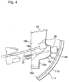
- FIG. 4 is a view illustrating the connecting process of the brake cable where the cable end fitting is guided onto the secondary seating;
- FIG. 5 is a view illustrating the connecting process of the brake cable where the cable end fitting is guided onto the primary seating while rotating the brake lever;
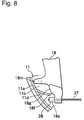
- FIG. 8 is a partial plan view of the connecting section of another embodiment where the projection is formed on the brake shoe.
- FIG. 1 shows a plan view of a leading-trailing type drum brake device.
- a plate-like brake lever 18 is superposed on the back plate, side surface, of the right shoe web 11b, and a proximal end 18a is pivotally supported by a pin 19 around an upper side of the shoe web 11b.
- a stopper 18n projects from a non-back plate side surface of the brake lever 18 between both ends of the brake lever 18 and abuts against the inner circumference of the shoe web 11b, thereby restricting the counterclockwise rotation of the brake lever 18 in the cable releasing direction.
- a shoe clearance adjustment strut 20, one of the components constituting a parking brake mechanism, is provided adjacent to the wheel cylinder 15, and is extended between the shoe web 12b of the left brake shoe 12 and the brake lever 18.
- Shoe return springs 24, 25 are stretched between both brake shoes 11 and 12, which urge both brake shoes 11 and 12 toward each other.
- the shoe clearance adjustment strut 20 restricts the initial positions of the brake shoes 11, 12.
- a brake cable 26 is comprised of an inner cable 27, a cable end fitting 28, and an outer casing 29.
- a brake side of the inner cable 27, slidably provided in the outer casing 29, is smoothly guided in an appropriate direction by a protrusion 10a formed on the back plate 10, and the cable end fitting 28, fixed on an end of the inner cable 27, is seated on a primary seating 18e of the brake lever 18.
- the other side of the inner cable 27 is connected to a parking brake operating lever in a driver's compartment, which is located outside of the figures.
- the other side of the outer casing 29 is fixed to the vehicle body, which is also located outside of the figures.
- FIG. 3 illustrates a connecting section between the brake lever 18 and the brake cable 26 as viewed from the back plate side.
- FIG. 4 illustrates a condition where the cable end fitting 28 is being guided to a secondary seating 18g.
- the brake lever 18 has a folded section 18c at the free end 18b facing the back plate 10, where the folded section 18c, together with a main body of the brake lever 18, makes a U-shaped groove 18d for retention of the inner cable 27.
- the brake lever 18, at the free end 18b, has the primary seating 18e whereat the cable end fitting 28 abuts and is seated on an edge surface thereof at the cable releasing direction side and has bowfront portions 18f protruding from the primary seating 18e in the cable releasing direction.
- the cable disengagement prevention configuration of this embodiment that prevents the cable end fitting 28 from disengaging from the brake lever 18 after assembling the brake cable 26, is comprised of the inner surface of the shoe rim 11a of the brake shoe 11 and the bowfront portion 18f positioned between the secondary seating 18g and the primary seating 18e.
- a minimum requirement is that the cable disengagement prevention configuration, which prevents the cable end fitting 28 from passing through the gap only when the brake lever is rotated, is provided between the primary seating 18e and the secondary seating 18g.
- the distance between the bowfront portion 18f and the inner surface of the shoe rim 11a returns the initial minimum distance H.
- the shoe rim 11a of the brake shoe 11, facing the bowfront portion 18f between the secondary seating 18g and the primary seating 18e, may be cut and folded to form the projection 11d, and the cable disengagement prevention configuration may be comprised of the bowfront portion 18f and the projection 11d of the shoe rim 11a, thus preventing the disengagement of the cable end fitting 28 after assembly.
- the projection 11d may be formed in various ways such as by cutting and folding a portion of the shoe web 11b or using an extra pin on the shoe web 11b of the brake shoe 11.
- the minimum distance in the gap between the bowfront portion 18f of the brake lever 18 and a top of the projection 11d may be specified so that the cable end fitting 28 is prevented from passing therethrough while the brake lever 18 is not rotating.
- This arrangement eliminates a process of rotating the brake lever 18 by hand or with tool prior to assembly and facilitates the brake cable connecting work to the brake lever 18 by simply pulling the inner cable 27 as the cable end fitting 28 abuts against the secondary seating 18g.
- the brake shoe 11 has the projection 11d, which increases the effectiveness of cable disengagement prevention after connecting the brake cable 26 to the brake lever 11.
- the stopper 18m of the brake lever 18, restricting the return position of the brake lever 18 as it abuts against the inner surface of the shoe rim 11a, may be formed so that the cable end fitting 28 can be temporarily held in a pocket defined by the crank-shaped stopper 18m, the projection 11 d and the secondary seating 18g, thereby improving the engagement of the cable end fitting 28 with the secondary seating 18g.
- the projection composed of the cable disengagement prevention configuration and cooperating with the bowfront portion 18f, may be formed in various ways, such as by protruding a portion of the back plate 11 or by placing an additional pin on the back plate 11, as long as the projection is located between the primary seating and the secondary seating.
- a hooking portion of the shoe return spring extending between the brake shoes, may be designed such that an end of the hooking portion may project from the shoe web.
- the projecting, hooking portion of the shoe return spring functions as the cable disengagement prevention configuration in cooperation with the brake lever 18.
- This invention has the following advantages.
- This invention provides cable disengagement prevention configuration by allowing the cable end fitting to pass through the gap between the brake lever and the shoe rim only while the brake lever is rotating. Therefore, only the simple process of pulling the inner cable, without directly rotating the brake lever by hand or with tools, is necessary in order to connect the brake cable to the brake lever safely and reliably.
- the cable disengagement prevention configuration prevents the cable end fitting from traveling back, and passing through, the gap between the brake lever and the brake shoe, thereby reliably preventing the brake cable from disengaging from the brake lever.
- the cable disengagement prevention configuration is composed of the common brake shoe and the modified brake lever, no modification of the brake shoe is necessary, which eliminates the problems of increasing the production cost, decreasing the rigidity of the brake shoe because of forming the projection, and misassembly.
Landscapes
- Engineering & Computer Science (AREA)
- General Engineering & Computer Science (AREA)
- Mechanical Engineering (AREA)
- Braking Arrangements (AREA)
Abstract
Description
- This invention relates to a mechanical type drum brake device and more particularly to a brake cable connecting apparatus for a drum brake device with an improvement at a connecting section between a brake lever and a brake cable.
- A known conventional mechanical type drum brake device is such that an inner cable of a brake cable is retained in a U-shaped groove which is formed at a free end of a brake lever and that a cable end fitting fixed on one end of the inner cable is seated on an edge surface of the U-shaped groove at a cable releasing direction side.
- In the conventional mechanical type drum brake device, a cable disengagement prevention configuration, which prevents the brake cable from disengaging from the brake lever after installing the drum brake in a vehicle and before adjusting the brake cable stroke, has a disengagement prevention means in a brake shoe where a portion of the shoe rim is cut and folded to form a projection, which restricts a movement of the brake cable relative to the brake lever. The conventional type is disclosed in Japanese utility model registration bulletin number 2520404 (pages 2-5, figures 1-4).
- The above-described drum brake device with the conventional cable disengagement prevention configuration has the following points to be improved.
- A process of connecting the brake cable to the brake lever requires seating the cable end fitting on the edge surface of the U-shaped groove formed at the free end of the brake lever at the cable releasing direction side while rotating the brake lever. A spring force of shoe return springs acts on the brake lever, which requires a large force in order to rotate the brake lever in a cable operating direction.
- Where the force causing the rotation of the brake lever is inadvertently released during the brake cable connecting process it is possible for the brake lever to snap back to an initial position due to the urging force of the shoe return springs. In this case there is risk of injuring fingers and/or a thumb by being caught between the brake lever and a web of the brake shoe.
- In order to connect the brake cable to the brake lever the brake cable must be controlled under extremely adverse condition, i.e., passing the brake cable through a barely visible interstice between a back plate and the brake shoe. This creates poor work efficiency and requires skilled work.
- Because of the poor work efficiency, a checking step is necessary for the conventional device to assure that the brake cable is reliably connected to the brake lever.
- This invention is made to improve the above-described problems and the objects of this invention are to provide a brake cable connecting apparatus for a drum brake device which affords connection of the brake cable to the brake lever in a safe and simple manner and to reliably prevent disengagement of the brake cable after connecting the brake cable to the brake lever.
- In order to attain the above-objects, this invention provides the brake cable connecting apparatus for the drum brake. The brake cable connecting apparatus for a drum brake device, may comprises a brake lever, a proximal portion thereof pivotally supported on a brake shoe so as to move at least one brake shoe outwardly, a U-shaped groove formed in a distal portion thereof, and a primary seating provided around the U-shaped groove at a cable releasing side; and a brake cable, an inner cable thereof retained in the U-shaped groove, and a cable end fitting thereof, fixed on one end of the inner cable, is seated on the primary seating, wherein secondary seating of the brake lever provided around the U-shaped groove at both the cable releasing direction side and an opening side of the U-shaped groove and also provided apart from the primary seating, on which the cable end fitting is temporarily seated; and a cable disengagement prevention configuration, provided between the primary seating and the secondary seating, the configuration allows the cable end fitting to pass between the primary and secondary seatings only upon rotating the brake lever but prevents the cable end fitting from passing between the primary and secondary seatings upon not rotating the brake lever.
- The cable connecting apparatus for the drum brake device as above may have the cable disengagement prevention configuration that is composed of the brake lever and the brake shoe.
- The cable connecting apparatus for the drum brake device as above may have the cable disengagement prevention configuration that is composed of the brake lever and a shoe rim of the brake shoe.
- The cable connecting apparatus for the drum brake device as above may have the primary seating and the secondary seating of the brake lever that are together formed in a step-like surface.
- According to the above-mentioned brake cable connecting apparatus for the drum brake device, the brake lever does not need to directly be rotated manually by hand or with tools to connect the brake cable. This invention allows the brake cable to connect to the brake lever simply by pulling the inner cable in a state of temporarily seating the cable end fitting on the secondary seating of the brake lever, which improves the work efficiency and the reliability of the brake cable connection.
- The cable disengagement prevention configuration prevents the cable end fitting from traveling back between the primary and the secondary seatings after connecting the brake cable to the brake lever, which reliably prevents the brake cable from being disengaged from the brake lever.
- The cable disengagement prevention configuration is composed of the brake lever and the brake shoe, especially the brake lever and an inner surface of the shoe rim, which simply realizes the configuration. The primary seating and the secondary seating of the brake lever are together formed in a step-like surface, which extends the usability. Furthermore, the cable end fitting impinges on the primary seating, and therefore, an impinging sound and assembler's sense give assurance of connection between the brake cable and the brake lever.
- FIG. 1 is a plan view of the mechanical type drum brake device of this invention;
- FIG. 2 is a cross sectional view of FIG. 1 taken along the line II-II;
- FIG. 3 is a partial perspective view of the connecting section between the brake lever and the brake cable viewed from the back plate side;
- FIG. 4 is a view illustrating the connecting process of the brake cable where the cable end fitting is guided onto the secondary seating;
- FIG. 5 is a view illustrating the connecting process of the brake cable where the cable end fitting is guided onto the primary seating while rotating the brake lever;
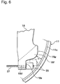
- FIG. 6 is a view illustrating the brake cable where the cable end fitting was guided onto the primary seating and the connection was completed;
- FIG. 7 is a partial plan view of the connecting section of another embodiment where the projection is provided at the end of the secondary seating; and
- FIG. 8 is a partial plan view of the connecting section of another embodiment where the projection is formed on the brake shoe.
- Referring to FIGS. 1-6, one embodiment of the brake cable connecting apparatus for the drum brake device as disclosed in this invention will be explained. Terms, "upper", "lower", "right" and "left" in a description below refer to "upper", "lower", "right" and "left" in FIG. 1 unless specifically stated otherwise.
- FIG. 1 shows a plan view of a leading-trailing type drum brake device.
- A pair of facing
brake shoes shoe rims shoe web brake shoes Linings shoe rims brake shoes back plate 10, which is fixed on a stationary part of a vehicle, by means ofshoe hold mechanisms - Upper adjacent ends of the
shoe webs wheel cylinder 15 fixed on theback plate 10 while lower adjacent ends of theshoe webs anchor block 16, also fixed on theback plate 10. - A plate-
like brake lever 18 is superposed on the back plate, side surface, of theright shoe web 11b, and aproximal end 18a is pivotally supported by apin 19 around an upper side of theshoe web 11b. Astopper 18n projects from a non-back plate side surface of thebrake lever 18 between both ends of thebrake lever 18 and abuts against the inner circumference of theshoe web 11b, thereby restricting the counterclockwise rotation of thebrake lever 18 in the cable releasing direction. - A shoe
clearance adjustment strut 20, one of the components constituting a parking brake mechanism, is provided adjacent to thewheel cylinder 15, and is extended between theshoe web 12b of theleft brake shoe 12 and thebrake lever 18. -
Shoe return springs brake shoes brake shoes clearance adjustment strut 20 restricts the initial positions of thebrake shoes - A
brake cable 26 is comprised of aninner cable 27, a cable end fitting 28, and anouter casing 29. - A brake side of the
inner cable 27, slidably provided in theouter casing 29, is smoothly guided in an appropriate direction by aprotrusion 10a formed on theback plate 10, and the cable end fitting 28, fixed on an end of theinner cable 27, is seated on aprimary seating 18e of thebrake lever 18. - A
casing cap 29a, fixed on a brake side end of theouter casing 29, is attached onto apipe 30 fixed on theback plate 10. - The other side of the
inner cable 27 is connected to a parking brake operating lever in a driver's compartment, which is located outside of the figures. The other side of theouter casing 29 is fixed to the vehicle body, which is also located outside of the figures. - FIG. 3 illustrates a connecting section between the
brake lever 18 and thebrake cable 26 as viewed from the back plate side. FIG. 4 illustrates a condition where the cable end fitting 28 is being guided to asecondary seating 18g. Referring to FIGS. 3 and 4, a connecting mechanism, the structure of thebrake cable 26 and thebrake lever 18 is explained. Thebrake lever 18 has a foldedsection 18c at thefree end 18b facing theback plate 10, where the foldedsection 18c, together with a main body of thebrake lever 18, makes aU-shaped groove 18d for retention of theinner cable 27. - The brake lever 18, at the
free end 18b, has theprimary seating 18e whereat the cable end fitting 28 abuts and is seated on an edge surface thereof at the cable releasing direction side and hasbowfront portions 18f protruding from theprimary seating 18e in the cable releasing direction. - The
brake lever 18, upper right of thebowfront portions 18f, also has thesecondary seating 18g on which the cable end fitting 28 is seated in order to establish engagement with thebrake lever 18. Thesecondary seating 18g is arranged so that a gap between theshoe rim 11a and the facing surface of thebowfront portion 18f allows the cable end fitting 28 to enter the gap at an entrance side but prevents it from passing therethrough at an exit side labeled as H in FIG. 4. More precisely, the gap is configured to allow the cable end fitting 28 to pass therethrough only when thebrake lever 18 is slightly rotated. - As is evident from the above-description, the cable disengagement prevention configuration of this embodiment that prevents the cable end fitting 28 from disengaging from the
brake lever 18 after assembling thebrake cable 26, is comprised of the inner surface of theshoe rim 11a of thebrake shoe 11 and thebowfront portion 18f positioned between thesecondary seating 18g and theprimary seating 18e. A minimum requirement is that the cable disengagement prevention configuration, which prevents the cable end fitting 28 from passing through the gap only when the brake lever is rotated, is provided between theprimary seating 18e and thesecondary seating 18g. - A ramped, guiding
surface 18k, at an upper marginal end of the foldedsection 18c, is designed to guide the cable end fitting 28 thereon. This is not a prerequisite of this invention however. - Referring to FIGS. 4-6, the connecting operation of the
brake cable 26 to thebrake lever 18 will be explained next. - As shown in a two-dot chain line of FIG. 4, while the assembler is pinching the
inner cable 27 near the cable end fitting 28, the cable end fitting 28 is pushed toward the cable releasing direction side of theU-shaped groove 18d along the upward ramped guidingsurface 18k. After reaching the top of the upward ramped guidingsurface 18k, the end surface of the cable end fitting 28 drops into place to be engaged with and is seated on thesecondary seating 18g. - When the
inner cable 27 is pulled while the cable end fitting 28 is being seated on thesecondary seating 18g, the cable end fitting 28 slides along the downward ramped surface of thesecondary seating 18g and thebowfront portion 18f whereafter the cable end fitting 28 reaches theprimary seating 18e. - The minimum distance H between the
bowfront portion 18f and the inner surface of theshoe rim 11a is configured so that the cable end fitting 28 is prevented from passing through the gap while thebrake lever 18 is not being rotated. When the cable end fitting 28 passes through the gap between thebowfront portion 18f and the inner surface of theshoe rim 11a, thebrake lever 18 in the initial position, as shown in the two-dot chain line of FIG. 5, rotates in the cable operating direction, as shown by the solid line. - As shown in FIG. 6, after the cable end fitting 28 passes through the gap between the
bowfront portion 18f and the inner surface of theshoe rim 11a, theinner cable 27 is retained in theU-shaped groove 18d, and the cable end fitting 28 abuts against, and is seated on, theprimary seating 18e. - After the cable end fitting 28 passes through the gap and as the
brake lever 18 returns to the initial position, the distance between thebowfront portion 18f and the inner surface of theshoe rim 11a returns the initial minimum distance H. - Accordingly, even if an external force, in the cable releasing direction, is acted on the
inner cable 27, travel of the cable end fitting 28 is interfered with by the cable disengagement prevention configuration, comprised of thebowfront portion 18f and the inner surface of theshoe rim 11a, thereby preventing theinner cable 27 from popping out from theU-shaped groove 18d and assuring cable end disengagement prevention. - Here, the parking brake operation is common and publicly known, the explanation of which is omitted.
- This invention is not limited to what is described in the previous embodiment. This invention may be employed where, even if the
brake lever 18 is superposed on a shoe web surface of thebrake shoe 11, opposite to the previous embodiment, and the foldedsection 18c, formed on thefree end 18b, is bent in a direction away from theshoe web 11b. - Additionally, as shown in FIG. 7, if a
protrusion 18i is protruding from an upper part of thesecondary seating 18g toward the cable releasing direction, the cable end fitting 28, seated on thesecondary seating 18g, abuts against theprotrusion 18i regardless of any irregularity in the angle ofinner cable 27 as it is being pulled, which prevents the cable end fitting 28 from disengagement from theprimary seating 18e and certainly improves the connection between thebrake cable 26 and thebrake lever 18. - As shown in FIG. 8, the
shoe rim 11a of thebrake shoe 11, facing thebowfront portion 18f between thesecondary seating 18g and theprimary seating 18e, may be cut and folded to form theprojection 11d, and the cable disengagement prevention configuration may be comprised of thebowfront portion 18f and theprojection 11d of theshoe rim 11a, thus preventing the disengagement of the cable end fitting 28 after assembly. - The
projection 11d may be formed in various ways such as by cutting and folding a portion of theshoe web 11b or using an extra pin on theshoe web 11b of thebrake shoe 11. - In this example, the minimum distance in the gap between the
bowfront portion 18f of thebrake lever 18 and a top of theprojection 11d may be specified so that the cable end fitting 28 is prevented from passing therethrough while thebrake lever 18 is not rotating. This arrangement eliminates a process of rotating thebrake lever 18 by hand or with tool prior to assembly and facilitates the brake cable connecting work to thebrake lever 18 by simply pulling theinner cable 27 as the cable end fitting 28 abuts against thesecondary seating 18g. In addition to thebowfront portion 18f, thebrake shoe 11 has theprojection 11d, which increases the effectiveness of cable disengagement prevention after connecting thebrake cable 26 to thebrake lever 11. - The
stopper 18m of thebrake lever 18, restricting the return position of thebrake lever 18 as it abuts against the inner surface of theshoe rim 11a, may be formed so that the cable end fitting 28 can be temporarily held in a pocket defined by the crank-shapedstopper 18m, theprojection 11 d and thesecondary seating 18g, thereby improving the engagement of the cable end fitting 28 with thesecondary seating 18g. - The projection, composed of the cable disengagement prevention configuration and cooperating with the
bowfront portion 18f, may be formed in various ways, such as by protruding a portion of theback plate 11 or by placing an additional pin on theback plate 11, as long as the projection is located between the primary seating and the secondary seating. - There are various other ways to form the cable disengagement prevention configuration that are obvious in consideration of the disclosure herein. For example, a hooking portion of the shoe return spring, extending between the brake shoes, may be designed such that an end of the hooking portion may project from the shoe web. Here the projecting, hooking portion of the shoe return spring functions as the cable disengagement prevention configuration in cooperation with the
brake lever 18. - Also, the type of the drum brake device in which this invention may be employed is not limited to the leading-trailing type. This invention is applicable to various other types of drum brake devices, such as a duo-servo type or a drum brake device without the
wheel cylinder 15, specially designed for a parking brake. - This invention has the following advantages.
- This invention provides cable disengagement prevention configuration by allowing the cable end fitting to pass through the gap between the brake lever and the shoe rim only while the brake lever is rotating. Therefore, only the simple process of pulling the inner cable, without directly rotating the brake lever by hand or with tools, is necessary in order to connect the brake cable to the brake lever safely and reliably.
- After connecting the brake cable to the brake lever, the cable disengagement prevention configuration prevents the cable end fitting from traveling back, and passing through, the gap between the brake lever and the brake shoe, thereby reliably preventing the brake cable from disengaging from the brake lever.
- If the cable disengagement prevention configuration is composed of the common brake shoe and the modified brake lever, no modification of the brake shoe is necessary, which eliminates the problems of increasing the production cost, decreasing the rigidity of the brake shoe because of forming the projection, and misassembly.
Claims (6)
- A brake cable connecting apparatus for a drum brake device, comprising:a brake lever, a proximal portion thereof pivotally supported on a brake shoe so as to move at least one brake shoe outwardly, a U-shaped groove formed in a distal portion thereof, and a primary seating provided around the U-shaped groove at a cable releasing side; anda brake cable, an inner cable thereof retained in the U-shaped groove, and a cable end fitting thereof, fixed on one end of the inner cable, is seated on the primary seating, characterized in thatsecondary seating of the brake lever provided around the U-shaped groove at both the cable releasing direction side and an opening side of the U-shaped groove and also provided apart from the primary seating, on which the cable end fitting is temporarily seated; anda cable disengagement prevention configuration, provided between the primary seating and the secondary seating, said configuration allows the cable end fitting to pass between the primary and secondary seatings only upon rotating the brake lever but prevents the cable end fitting from passing between the primary and secondary seatings upon not rotating the brake lever.
- The cable connecting apparatus for the drum brake device according to Claim 1, characterized in that
the cable disengagement prevention configuration is composed of the brake lever and the brake shoe. - The cable connecting apparatus for the drum brake device according to Claim 2, characterized in that
the cable disengagement prevention configuration is composed of the brake lever and a shoe rim of the brake shoe. - The cable connecting apparatus for the drum brake device according to Claim 1, characterized in that
the primary seating and the secondary seating of the brake lever are together formed in a step-like surface. - The cable connecting apparatus for the drum brake device according to Claim 2, characterized in that
the primary seating and the secondary seating of the brake lever are together formed in a step-like surface. - The cable connecting apparatus for the drum brake device according to Claim 3, characterized in that
the primary seating and the secondary seating of the brake lever are together formed in a step-like surface.
Applications Claiming Priority (2)
| Application Number | Priority Date | Filing Date | Title |
|---|---|---|---|
| JP2003034231A JP4242659B2 (en) | 2003-02-12 | 2003-02-12 | Brake cable connection device for drum brake |
| JP2003034231 | 2003-02-12 |
Publications (3)
| Publication Number | Publication Date |
|---|---|
| EP1447586A2 true EP1447586A2 (en) | 2004-08-18 |
| EP1447586A3 EP1447586A3 (en) | 2004-11-17 |
| EP1447586B1 EP1447586B1 (en) | 2006-10-11 |
Family
ID=32677591
Family Applications (1)
| Application Number | Title | Priority Date | Filing Date |
|---|---|---|---|
| EP04290360A Expired - Lifetime EP1447586B1 (en) | 2003-02-12 | 2004-02-11 | Brake cable connecting apparatus for a drum brake device |
Country Status (4)
| Country | Link |
|---|---|
| US (1) | US6962241B2 (en) |
| EP (1) | EP1447586B1 (en) |
| JP (1) | JP4242659B2 (en) |
| DE (1) | DE602004002705T2 (en) |
Cited By (1)
| Publication number | Priority date | Publication date | Assignee | Title |
|---|---|---|---|---|
| US6962241B2 (en) * | 2003-02-12 | 2005-11-08 | Nisshinbo Industries, Inc. | Brake cable connecting apparatus for a drum brake device |
Families Citing this family (7)
| Publication number | Priority date | Publication date | Assignee | Title |
|---|---|---|---|---|
| JP2006105209A (en) * | 2004-10-01 | 2006-04-20 | Nisshinbo Ind Inc | Brake cable connection device for drum brake |
| DE102007037671A1 (en) * | 2007-08-09 | 2009-02-12 | Lucas Automotive Gmbh | Bracket for the handbrake lever of a drum brake during initial assembly to produce a permanent bias of the Bowden cable |
| DE102007051824A1 (en) * | 2007-10-30 | 2009-05-07 | Iwis Motorsysteme Gmbh & Co. Kg | Clamping device with an adjusting device |
| US8267227B2 (en) * | 2008-07-22 | 2012-09-18 | Akebono Brake Corporation | Lever assembly featuring blind cable assembly |
| US20110100772A1 (en) * | 2009-11-05 | 2011-05-05 | Akebono Corporation (North America) | Cable end retention clip assembly and method |
| DE102014213189A1 (en) | 2014-07-08 | 2016-01-14 | Continental Teves Ag & Co. Ohg | Guide system for a brake actuation cable |
| IT201600105859A1 (en) * | 2016-10-20 | 2018-04-20 | Freni Brembo Spa | Implementation assembly of a parking brake |
Family Cites Families (9)
| Publication number | Priority date | Publication date | Assignee | Title |
|---|---|---|---|---|
| JPH08252040A (en) | 1995-03-16 | 1996-10-01 | Ryobi Ltd | Fishline guide implement for fishing rod |
| JP3687058B2 (en) * | 1997-02-12 | 2005-08-24 | 日清紡績株式会社 | Control cable connection device |
| JP4397080B2 (en) * | 1999-11-02 | 2010-01-13 | 日清紡ホールディングス株式会社 | Operation cable connection device |
| JP2001140958A (en) * | 1999-11-11 | 2001-05-22 | Nisshinbo Ind Inc | Operation cable connection device |
| JP3283028B2 (en) * | 2000-02-24 | 2002-05-20 | 豊生ブレーキ工業株式会社 | Brake cable connection device |
| US20010017245A1 (en) * | 2000-02-24 | 2001-08-30 | Hosei Brake Ind. Co., Ltd. | Brake cable connector device for connecting brake cable to brake lever in brake device |
| JP4381620B2 (en) * | 2001-02-23 | 2009-12-09 | 日清紡ホールディングス株式会社 | Brake cable connection device |
| JP2002364688A (en) * | 2001-06-08 | 2002-12-18 | Nisshinbo Ind Inc | Brake cable connection device |
| JP4242659B2 (en) * | 2003-02-12 | 2009-03-25 | 日清紡績株式会社 | Brake cable connection device for drum brake |
-
2003
- 2003-02-12 JP JP2003034231A patent/JP4242659B2/en not_active Expired - Fee Related
-
2004
- 2004-02-11 EP EP04290360A patent/EP1447586B1/en not_active Expired - Lifetime
- 2004-02-11 DE DE602004002705T patent/DE602004002705T2/en not_active Expired - Fee Related
- 2004-02-12 US US10/777,738 patent/US6962241B2/en not_active Expired - Fee Related
Cited By (1)
| Publication number | Priority date | Publication date | Assignee | Title |
|---|---|---|---|---|
| US6962241B2 (en) * | 2003-02-12 | 2005-11-08 | Nisshinbo Industries, Inc. | Brake cable connecting apparatus for a drum brake device |
Also Published As
| Publication number | Publication date |
|---|---|
| US20040159506A1 (en) | 2004-08-19 |
| EP1447586A3 (en) | 2004-11-17 |
| DE602004002705D1 (en) | 2006-11-23 |
| JP4242659B2 (en) | 2009-03-25 |
| DE602004002705T2 (en) | 2007-06-14 |
| EP1447586B1 (en) | 2006-10-11 |
| JP2004245288A (en) | 2004-09-02 |
| US6962241B2 (en) | 2005-11-08 |
Similar Documents
| Publication | Publication Date | Title |
|---|---|---|
| US8360130B2 (en) | Active tension device for a window covering | |
| EP1447586B1 (en) | Brake cable connecting apparatus for a drum brake device | |
| US6651782B2 (en) | Brake cable connecting apparatus for drum brake | |
| RU2633137C2 (en) | Brake lining of disc brake and disc brake | |
| EP1099874A2 (en) | Brake cable-fixing device for a parking brake | |
| US6241051B1 (en) | Brake cable connecting device for drum brake | |
| US6502670B1 (en) | Mechanical type drum brake device | |
| EP1752679B1 (en) | Mechanical brake actuator | |
| JPH0221457B2 (en) | ||
| JP4171550B2 (en) | Cable pulling parking brake | |
| US6679354B1 (en) | Actuator mechanism for drum in hat brake | |
| JP6198889B1 (en) | Drum brake for vehicles | |
| EP1643153A2 (en) | Brake cable connecting apparatus for a drum brake device | |
| EP1108916A2 (en) | Brake cable mounting structure for a drum brake | |
| JP2012036959A (en) | Drum brake for vehicle | |
| JPH0722504Y2 (en) | Drum brake with automatic shoe clearance adjuster | |
| JP2520404Y2 (en) | Drum brake with parking brake mechanism | |
| US5366049A (en) | Drum brake shoe hold-down bracket and cable guide | |
| KR20140132042A (en) | Shoe fixing device for parking brake in vehicle | |
| JPS642993Y2 (en) | ||
| JPH0966819A (en) | Parking brake device | |
| JPS5912432Y2 (en) | Vehicle drum brake | |
| JPH0638190Y2 (en) | Duo servo type drum brake | |
| JP2003232389A (en) | Cable coupling apparatus for brake device | |
| KR200281980Y1 (en) | Actuating lever of mechanical drum brake |
Legal Events
| Date | Code | Title | Description |
|---|---|---|---|
| PUAI | Public reference made under article 153(3) epc to a published international application that has entered the european phase |
Free format text: ORIGINAL CODE: 0009012 |
|
| AK | Designated contracting states |
Kind code of ref document: A2 Designated state(s): AT BE BG CH CY CZ DE DK EE ES FI FR GB GR HU IE IT LI LU MC NL PT RO SE SI SK TR |
|
| AX | Request for extension of the european patent |
Extension state: AL LT LV MK |
|
| PUAL | Search report despatched |
Free format text: ORIGINAL CODE: 0009013 |
|
| AK | Designated contracting states |
Kind code of ref document: A3 Designated state(s): AT BE BG CH CY CZ DE DK EE ES FI FR GB GR HU IE IT LI LU MC NL PT RO SE SI SK TR |
|
| AX | Request for extension of the european patent |
Extension state: AL LT LV MK |
|
| RIC1 | Information provided on ipc code assigned before grant |
Ipc: 7F 16D 65/22 A |
|
| 17P | Request for examination filed |
Effective date: 20050517 |
|
| AKX | Designation fees paid |
Designated state(s): DE FR |
|
| GRAP | Despatch of communication of intention to grant a patent |
Free format text: ORIGINAL CODE: EPIDOSNIGR1 |
|
| GRAS | Grant fee paid |
Free format text: ORIGINAL CODE: EPIDOSNIGR3 |
|
| GRAA | (expected) grant |
Free format text: ORIGINAL CODE: 0009210 |
|
| AK | Designated contracting states |
Kind code of ref document: B1 Designated state(s): DE FR |
|
| REF | Corresponds to: |
Ref document number: 602004002705 Country of ref document: DE Date of ref document: 20061123 Kind code of ref document: P |
|
| EN | Fr: translation not filed | ||
| PLBE | No opposition filed within time limit |
Free format text: ORIGINAL CODE: 0009261 |
|
| STAA | Information on the status of an ep patent application or granted ep patent |
Free format text: STATUS: NO OPPOSITION FILED WITHIN TIME LIMIT |
|
| 26N | No opposition filed |
Effective date: 20070712 |
|
| PG25 | Lapsed in a contracting state [announced via postgrant information from national office to epo] |
Ref country code: FR Free format text: LAPSE BECAUSE OF FAILURE TO SUBMIT A TRANSLATION OF THE DESCRIPTION OR TO PAY THE FEE WITHIN THE PRESCRIBED TIME-LIMIT Effective date: 20070601 |
|
| PG25 | Lapsed in a contracting state [announced via postgrant information from national office to epo] |
Ref country code: FR Free format text: LAPSE BECAUSE OF FAILURE TO SUBMIT A TRANSLATION OF THE DESCRIPTION OR TO PAY THE FEE WITHIN THE PRESCRIBED TIME-LIMIT Effective date: 20061011 |
|
| PGFP | Annual fee paid to national office [announced via postgrant information from national office to epo] |
Ref country code: DE Payment date: 20090206 Year of fee payment: 6 |
|
| PG25 | Lapsed in a contracting state [announced via postgrant information from national office to epo] |
Ref country code: DE Free format text: LAPSE BECAUSE OF NON-PAYMENT OF DUE FEES Effective date: 20100901 |