US5366049A - Drum brake shoe hold-down bracket and cable guide - Google Patents
Drum brake shoe hold-down bracket and cable guide Download PDFInfo
- Publication number
- US5366049A US5366049A US08/163,020 US16302093A US5366049A US 5366049 A US5366049 A US 5366049A US 16302093 A US16302093 A US 16302093A US 5366049 A US5366049 A US 5366049A
- Authority
- US
- United States
- Prior art keywords
- brake
- backing plate
- cable guide
- drum brake
- brake shoe
- Prior art date
- Legal status (The legal status is an assumption and is not a legal conclusion. Google has not performed a legal analysis and makes no representation as to the accuracy of the status listed.)
- Expired - Lifetime
Links
Images

Classifications
-
- F—MECHANICAL ENGINEERING; LIGHTING; HEATING; WEAPONS; BLASTING
- F16—ENGINEERING ELEMENTS AND UNITS; GENERAL MEASURES FOR PRODUCING AND MAINTAINING EFFECTIVE FUNCTIONING OF MACHINES OR INSTALLATIONS; THERMAL INSULATION IN GENERAL
- F16D—COUPLINGS FOR TRANSMITTING ROTATION; CLUTCHES; BRAKES
- F16D51/00—Brakes with outwardly-movable braking members co-operating with the inner surface of a drum or the like
- F16D51/46—Self-tightening brakes with pivoted brake shoes, i.e. the braked member increases the braking action
- F16D51/48—Self-tightening brakes with pivoted brake shoes, i.e. the braked member increases the braking action with two linked or directly-interacting brake shoes
-
- F—MECHANICAL ENGINEERING; LIGHTING; HEATING; WEAPONS; BLASTING
- F16—ENGINEERING ELEMENTS AND UNITS; GENERAL MEASURES FOR PRODUCING AND MAINTAINING EFFECTIVE FUNCTIONING OF MACHINES OR INSTALLATIONS; THERMAL INSULATION IN GENERAL
- F16D—COUPLINGS FOR TRANSMITTING ROTATION; CLUTCHES; BRAKES
- F16D51/00—Brakes with outwardly-movable braking members co-operating with the inner surface of a drum or the like
- F16D51/16—Brakes with outwardly-movable braking members co-operating with the inner surface of a drum or the like shaped as brake-shoes pivoted on a fixed or nearly-fixed axis
-
- F—MECHANICAL ENGINEERING; LIGHTING; HEATING; WEAPONS; BLASTING
- F16—ENGINEERING ELEMENTS AND UNITS; GENERAL MEASURES FOR PRODUCING AND MAINTAINING EFFECTIVE FUNCTIONING OF MACHINES OR INSTALLATIONS; THERMAL INSULATION IN GENERAL
- F16D—COUPLINGS FOR TRANSMITTING ROTATION; CLUTCHES; BRAKES
- F16D65/00—Parts or details
- F16D65/02—Braking members; Mounting thereof
- F16D65/04—Bands, shoes or pads; Pivots or supporting members therefor
- F16D65/08—Bands, shoes or pads; Pivots or supporting members therefor for internally-engaging brakes
- F16D65/09—Pivots or supporting members therefor
- F16D65/091—Pivots or supporting members therefor for axially holding the segments
-
- F—MECHANICAL ENGINEERING; LIGHTING; HEATING; WEAPONS; BLASTING
- F16—ENGINEERING ELEMENTS AND UNITS; GENERAL MEASURES FOR PRODUCING AND MAINTAINING EFFECTIVE FUNCTIONING OF MACHINES OR INSTALLATIONS; THERMAL INSULATION IN GENERAL
- F16D—COUPLINGS FOR TRANSMITTING ROTATION; CLUTCHES; BRAKES
- F16D2125/00—Components of actuators
- F16D2125/18—Mechanical mechanisms
- F16D2125/58—Mechanical mechanisms transmitting linear movement
- F16D2125/60—Cables or chains, e.g. Bowden cables
Definitions
- the present invention relates generally to a drum brake, and in particular to a drum brake having a combination drum brake shoe hold-down bracket and cable guide.
- drum brakes include a parking brake lever for parking brake actuation of the drum brake shoes.
- the parking brake lever is connected with a cable received slidably within a parking brake cable assembly that extends through an opening in the backing plate of the drum brake. It is highly desirable that the parking brake assembly does not interfere with other drum brake components such as an adjuster mechanism, a spring extending between opposing ends of the drum brake shoes, and the brake shoes themselves. It is also necessary for the drum brake shoes to be held in operative position so that they will not lift off, i.e. move axially away from, the backing plate which supports them. It is highly desirable that the axial retention of the drum brake shoes be combined with a mechanism which prevents the parking brake cable assembly from interfering with other brake components.
- a drum brake having a combination brake shoe hold-down bracket and cable guide, comprising a backing plate supporting thereon a pair of drum brake shoes, each of said drum brake shoes including a brake shoe web, actuation means for causing a first pair of brake shoe ends to move away from one another and into engagement with an adjacent rotatable drum, resilient means extending between the first pair of brake shoe ends and second resilient means extending between an opposite and second pair of brake shoe ends, a parking brake lever cooperating with means for effecting a parking application of said drum brake shoes, a combination hold-down bracket and cable guide connected with said backing plate and adjacent the second pair of brake shoe ends, and parking brake cable means extending into said drum brake and connected with an end of said parking brake lever, the combination hold-down bracket and cable guide comprising a metal member securely attached to said backing plate and having laterally extending projections which extend axially away from said backing plate and then transversely to a center of rotation of the drum brake such that respective bracket ends extend over respective brake shoe webs
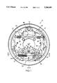
- FIG. 1 is a drum brake which includes the present invention
- FIG. 2 is a section view taken along view line 2--2 of FIG. 1;
- FIG. 3 is a section view taken along view line 3--3 of FIG. 1.
- Drum brake 10 is designated generally by reference numeral 10 in FIG. 1.
- Drum brake 10 includes drum brake shoes 12 and 14 which include, respectively, drum brake shoe webs 16 and 18.
- Hydraulic actuator or wheel cylinder 20 is located between a first pair brake shoe ends 22 and 24 and an adjuster mechanism indicated generally by reference numeral 30 is located between a second pair of brake shoe ends 26, 28.
- Return spring 29 extends between brake shoe ends 22 and 24, while return spring 31 extends between brake shoe ends 26 and 28.
- a parking brake lever 35 is pivoted on pivot pin 51 and engages cam 49 which displaces brake shoes 12 and 14 for a parking brake application, and has end 37 receiving cable end 41 of a parking brake cable assembly designated generally by reference numeral 40.
- Cable 50 is attached at one end to pivot pin 51 and at the other end to adjuster mechanism 30 to effect actuation thereof.
- the combination brake shoe hold-down bracket and cable guide is designated generally by reference numeral 60 and comprises a pair of securement portions 61 which are welded or riveted to backing or support plate 11. Each portion 61 extends axially away from backing plate 11 via an axially bent or axial projection 62 which, via a lateral retention portion or bracket end 64, spreads laterally or transversely relative to the center of rotation A of drum brake 10. Lateral retention portions 64 comprise wing members which engage drum brake shoe webs 16 and 18 to hold axially in place drum brake shoes 12 and 14. The drum brake shoes are free to move circumferentially outwardly or laterally relative to one another during operation of the drum brake.
- Each portion 61 also extends toward the other via an axially extending portion 65 which extends axially away from backing plate 11 and then curves in an annular path to terminate at cable guide end 66, with portions 65 and guide end 66 forming a substantially circular or annular center portion 67 that defines cable guide path 68 which receives parking brake cable assembly 40. Parking brake cable assembly 40 is captured within cable guide path 68 of the combination hold-down bracket and cable guide 60.
- drum brake shoes 12 and 14 may move away from one another or circumferentially outwardly such that the respective webs 16 and 18 slidably engage lateral retention portions 64 which permit such movement while retaining the drum brake shoes axially in operative position.
- the combination brake shoe hold-down bracket and cable guide 60 effects positioning of the parking brake cable assembly 40 so that it will not interfere with other brake components.
- Brake shoe hold-down bracket and cable guide 60 is a one-piece metal stamping which provides a positive retention of both drum brake shoes so that they will not lift off or move axially away from backing plate 11, while also providing guidance and retention of parking brake cable assembly 40.
- the combination bracket and cable guide is manufactured from a lighter weight, easier to form into shape metal which, when manufactured, produces zero scrap. The combination bracket and cable guide will hold both brake shoes in place throughout their service life.
Abstract
Description
Claims (4)
Priority Applications (3)
| Application Number | Priority Date | Filing Date | Title |
|---|---|---|---|
| US08/163,020 US5366049A (en) | 1993-12-07 | 1993-12-07 | Drum brake shoe hold-down bracket and cable guide |
| PCT/US1994/014064 WO1995016147A1 (en) | 1993-12-07 | 1994-12-07 | Drum brake shoe hold-down bracket and cable guide |
| AU13023/95A AU1302395A (en) | 1993-12-07 | 1994-12-07 | Drum brake shoe hold-down bracket and cable guide |
Applications Claiming Priority (1)
| Application Number | Priority Date | Filing Date | Title |
|---|---|---|---|
| US08/163,020 US5366049A (en) | 1993-12-07 | 1993-12-07 | Drum brake shoe hold-down bracket and cable guide |
Publications (1)
| Publication Number | Publication Date |
|---|---|
| US5366049A true US5366049A (en) | 1994-11-22 |
Family
ID=22588109
Family Applications (1)
| Application Number | Title | Priority Date | Filing Date |
|---|---|---|---|
| US08/163,020 Expired - Lifetime US5366049A (en) | 1993-12-07 | 1993-12-07 | Drum brake shoe hold-down bracket and cable guide |
Country Status (3)
| Country | Link |
|---|---|
| US (1) | US5366049A (en) |
| AU (1) | AU1302395A (en) |
| WO (1) | WO1995016147A1 (en) |
Cited By (2)
| Publication number | Priority date | Publication date | Assignee | Title |
|---|---|---|---|---|
| US6877592B2 (en) * | 2001-12-27 | 2005-04-12 | Nisshinbo Industries, Inc. | Mechanical actuator for a drum brake |
| US20110308903A1 (en) * | 2010-06-18 | 2011-12-22 | Chuo Hatsujo Kabushiki Kaisha | Cable-operated device and parking brake containing the same |
Families Citing this family (1)
| Publication number | Priority date | Publication date | Assignee | Title |
|---|---|---|---|---|
| CN114127435B (en) * | 2019-07-10 | 2023-11-24 | 日立安斯泰莫株式会社 | Drum brake for vehicle |
Citations (2)
| Publication number | Priority date | Publication date | Assignee | Title |
|---|---|---|---|---|
| US2294329A (en) * | 1940-05-13 | 1942-08-25 | Bendix Aviat Corp | Brake |
| US5159998A (en) * | 1991-08-02 | 1992-11-03 | General Motors Corporation | Unispring drum brake assembly |
Family Cites Families (2)
| Publication number | Priority date | Publication date | Assignee | Title |
|---|---|---|---|---|
| FR61231E (en) * | 1951-01-09 | 1955-04-05 | Bendix Aviat Corp | Brake improvements |
| US4886146A (en) * | 1988-12-19 | 1989-12-12 | General Motors Corporation | Blind cable assembly |
-
1993
- 1993-12-07 US US08/163,020 patent/US5366049A/en not_active Expired - Lifetime
-
1994
- 1994-12-07 WO PCT/US1994/014064 patent/WO1995016147A1/en active Application Filing
- 1994-12-07 AU AU13023/95A patent/AU1302395A/en not_active Abandoned
Patent Citations (2)
| Publication number | Priority date | Publication date | Assignee | Title |
|---|---|---|---|---|
| US2294329A (en) * | 1940-05-13 | 1942-08-25 | Bendix Aviat Corp | Brake |
| US5159998A (en) * | 1991-08-02 | 1992-11-03 | General Motors Corporation | Unispring drum brake assembly |
Cited By (3)
| Publication number | Priority date | Publication date | Assignee | Title |
|---|---|---|---|---|
| US6877592B2 (en) * | 2001-12-27 | 2005-04-12 | Nisshinbo Industries, Inc. | Mechanical actuator for a drum brake |
| US20110308903A1 (en) * | 2010-06-18 | 2011-12-22 | Chuo Hatsujo Kabushiki Kaisha | Cable-operated device and parking brake containing the same |
| US8397876B2 (en) * | 2010-06-18 | 2013-03-19 | Chuo Hatsujo Kabushiki Kaisha | Cable-operated device and parking brake containing the same |
Also Published As
| Publication number | Publication date |
|---|---|
| WO1995016147A1 (en) | 1995-06-15 |
| AU1302395A (en) | 1995-06-27 |
Similar Documents
| Publication | Publication Date | Title |
|---|---|---|
| US7040464B1 (en) | Brake shoe assembly and disc brake assembly including such a brake shoe assembly | |
| US4476968A (en) | Expanding shoe drum brake | |
| US8356701B2 (en) | Drum-in-hat disc brake assembly | |
| US8056684B2 (en) | Vehicle drum-in-hat disc brake assembly and method for producing same | |
| US4887698A (en) | Brake actuator | |
| US5630486A (en) | Mechanical actuation device for drum brake | |
| US6360852B1 (en) | Drum-in-hat park brake assembly | |
| GB2039646A (en) | Disc brake | |
| US3351159A (en) | Backing plate, anchor construction | |
| US6196360B1 (en) | Automatic shoe clearance adjustment device for drum brakes | |
| US5366049A (en) | Drum brake shoe hold-down bracket and cable guide | |
| EP1174627A1 (en) | Brake cable connecting apparatus for drum brake | |
| US6502670B1 (en) | Mechanical type drum brake device | |
| GB2153462A (en) | Drum brake | |
| US4051928A (en) | Automatic shoe clearance adjusting device in shoe drum brake | |
| US4595082A (en) | Drum brake | |
| EP0078115B1 (en) | Expanding shoe drum brake | |
| US4228876A (en) | Internal shoe drum brakes | |
| EP0066075B1 (en) | Roller retainer for brake assembly | |
| US20010037918A1 (en) | Brake cable mounting structure for a drum brake | |
| US4236614A (en) | Drum brake having parking mechaism | |
| GB2069078A (en) | A disc brake | |
| US4197928A (en) | Brake shoe guide and wheel cylinder retainer for a drum brake | |
| CA1112190A (en) | Drum brake having parking mechanism | |
| JPH0710110Y2 (en) | Drum brake |
Legal Events
| Date | Code | Title | Description |
|---|---|---|---|
| AS | Assignment |
Owner name: ALLIEDSIGNAL INC. Free format text: ASSIGNMENT OF ASSIGNORS INTEREST;ASSIGNOR:ALLEN, MARK EDWARD;REEL/FRAME:006825/0727 Effective date: 19931206 |
|
| STCF | Information on status: patent grant |
Free format text: PATENTED CASE |
|
| AS | Assignment |
Owner name: ROBERT BOSCH TECHNOLOGY CORPORATION, MICHIGAN Free format text: ASSIGNMENT OF ASSIGNORS INTEREST;ASSIGNOR:ALLIEDSIGNAL TECHNOLOGIES INC.;REEL/FRAME:008268/0568 Effective date: 19960411 Owner name: ALLIEDSIGNAL TECHNOLOGIES INC., ARIZONA Free format text: ASSIGNMENT OF ASSIGNORS INTEREST;ASSIGNOR:ALLIEDSIGNAL INC.;REEL/FRAME:008274/0207 Effective date: 19950901 |
|
| FEPP | Fee payment procedure |
Free format text: PAYOR NUMBER ASSIGNED (ORIGINAL EVENT CODE: ASPN); ENTITY STATUS OF PATENT OWNER: LARGE ENTITY |
|
| FEPP | Fee payment procedure |
Free format text: PAYOR NUMBER ASSIGNED (ORIGINAL EVENT CODE: ASPN); ENTITY STATUS OF PATENT OWNER: LARGE ENTITY Free format text: PAYER NUMBER DE-ASSIGNED (ORIGINAL EVENT CODE: RMPN); ENTITY STATUS OF PATENT OWNER: LARGE ENTITY |
|
| FPAY | Fee payment |
Year of fee payment: 4 |
|
| FPAY | Fee payment |
Year of fee payment: 8 |
|
| FPAY | Fee payment |
Year of fee payment: 12 |