EP1108916A2 - Brake cable mounting structure for a drum brake - Google Patents
Brake cable mounting structure for a drum brake Download PDFInfo
- Publication number
- EP1108916A2 EP1108916A2 EP00127159A EP00127159A EP1108916A2 EP 1108916 A2 EP1108916 A2 EP 1108916A2 EP 00127159 A EP00127159 A EP 00127159A EP 00127159 A EP00127159 A EP 00127159A EP 1108916 A2 EP1108916 A2 EP 1108916A2
- Authority
- EP
- European Patent Office
- Prior art keywords
- brake
- spacer
- anchor
- mounting structure
- drum
- Prior art date
- Legal status (The legal status is an assumption and is not a legal conclusion. Google has not performed a legal analysis and makes no representation as to the accuracy of the status listed.)
- Withdrawn
Links
Images


Classifications
-
- F—MECHANICAL ENGINEERING; LIGHTING; HEATING; WEAPONS; BLASTING
- F16—ENGINEERING ELEMENTS AND UNITS; GENERAL MEASURES FOR PRODUCING AND MAINTAINING EFFECTIVE FUNCTIONING OF MACHINES OR INSTALLATIONS; THERMAL INSULATION IN GENERAL
- F16D—COUPLINGS FOR TRANSMITTING ROTATION; CLUTCHES; BRAKES
- F16D65/00—Parts or details
- F16D65/14—Actuating mechanisms for brakes; Means for initiating operation at a predetermined position
- F16D65/16—Actuating mechanisms for brakes; Means for initiating operation at a predetermined position arranged in or on the brake
- F16D65/22—Actuating mechanisms for brakes; Means for initiating operation at a predetermined position arranged in or on the brake adapted for pressing members apart, e.g. for drum brakes
-
- F—MECHANICAL ENGINEERING; LIGHTING; HEATING; WEAPONS; BLASTING
- F16—ENGINEERING ELEMENTS AND UNITS; GENERAL MEASURES FOR PRODUCING AND MAINTAINING EFFECTIVE FUNCTIONING OF MACHINES OR INSTALLATIONS; THERMAL INSULATION IN GENERAL
- F16D—COUPLINGS FOR TRANSMITTING ROTATION; CLUTCHES; BRAKES
- F16D51/00—Brakes with outwardly-movable braking members co-operating with the inner surface of a drum or the like
- F16D51/46—Self-tightening brakes with pivoted brake shoes, i.e. the braked member increases the braking action
- F16D51/48—Self-tightening brakes with pivoted brake shoes, i.e. the braked member increases the braking action with two linked or directly-interacting brake shoes
- F16D51/50—Self-tightening brakes with pivoted brake shoes, i.e. the braked member increases the braking action with two linked or directly-interacting brake shoes mechanically actuated
-
- F—MECHANICAL ENGINEERING; LIGHTING; HEATING; WEAPONS; BLASTING
- F16—ENGINEERING ELEMENTS AND UNITS; GENERAL MEASURES FOR PRODUCING AND MAINTAINING EFFECTIVE FUNCTIONING OF MACHINES OR INSTALLATIONS; THERMAL INSULATION IN GENERAL
- F16D—COUPLINGS FOR TRANSMITTING ROTATION; CLUTCHES; BRAKES
- F16D2121/00—Type of actuator operation force
- F16D2121/14—Mechanical
-
- F—MECHANICAL ENGINEERING; LIGHTING; HEATING; WEAPONS; BLASTING
- F16—ENGINEERING ELEMENTS AND UNITS; GENERAL MEASURES FOR PRODUCING AND MAINTAINING EFFECTIVE FUNCTIONING OF MACHINES OR INSTALLATIONS; THERMAL INSULATION IN GENERAL
- F16D—COUPLINGS FOR TRANSMITTING ROTATION; CLUTCHES; BRAKES
- F16D2125/00—Components of actuators
- F16D2125/18—Mechanical mechanisms
- F16D2125/58—Mechanical mechanisms transmitting linear movement
- F16D2125/60—Cables or chains, e.g. Bowden cables
-
- F—MECHANICAL ENGINEERING; LIGHTING; HEATING; WEAPONS; BLASTING
- F16—ENGINEERING ELEMENTS AND UNITS; GENERAL MEASURES FOR PRODUCING AND MAINTAINING EFFECTIVE FUNCTIONING OF MACHINES OR INSTALLATIONS; THERMAL INSULATION IN GENERAL
- F16D—COUPLINGS FOR TRANSMITTING ROTATION; CLUTCHES; BRAKES
- F16D2125/00—Components of actuators
- F16D2125/18—Mechanical mechanisms
- F16D2125/58—Mechanical mechanisms transmitting linear movement
- F16D2125/68—Lever-link mechanisms, e.g. toggles with change of force ratio
Definitions
- This invention relates to a brake cable mounting structure suitable for a drum brake structure for a rear wheel. More specifically, this invention relates to a brake cable mounting structure which has a crank mechanism spreading a pair of brake shoes apart and is capable of remotely operating the crank mechanism.
- the brake cable mounting structure for the drum brake is disclosed in the Japanese Patent Application Unexamined Publication Number 6-337027 filed by this applicant.
- Figures 7-10 explain a drum brake device employing this brake cable mounting structure.
- a pair of brake shoes 110, 120 are moveably mounted on a back plate 100 by shoe hold mechanisms 111, 121.
- lower adjacent ends of the brake shoes 110, 120 are supported by a supporting portion 201 of an almost L-shaped anchor 200 while upper adjacent ends of the brake shoes 110, 120 are connected via an adjuster 130.
- An upper shoe return spring 160 is extended between the upper adjacent ends of the brake shoes 110, 120 and a lower shoe return spring 160 is extended between the lower adjacent ends of the brake shoes 110, 120, maintaining the abutment of the two brake shoes 110, 120 against the adjuster 130 and the anchor 200.
- a crank mechanism 300 comprises a brake lever 320, a strut 330 and a lever pin 310.
- the crank mechanism 300 is positioned adjacent to the supporting portion 201 of the anchor 200 between the two brake shoes 110, 120.
- the brake lever 320 comprises two facing elongated plates.
- a notched groove 321 formed at the superimposing portion on the right side of the plates in Figure 8 is functionally engaged with the right brake shoe 110.
- an arc-shaped groove 322 formed on forked legs on the left side of the two plates receives a cable end nipple 420 of a brake cable 400.
- the strut 330 integrally formed from a deformed piece of plate, comprises two facing plate portions connected on their upper edges by-a bridge 332 and positioned between the two brake shoes 110, 120.
- a notched groove 331 formed at the superimposing portion on the left side of the strut 330 in the Figure 8 is functionally engaged with the left brake shoe 120.
- the brake lever 320 is inserted from the opposite side of the bridge 332 into a space formed between the two facing plate portions of the strut 330, and upper right end of the brake lever 320 is pivotally supported relative to the strut 330 through the lever pin 310 acting as the fulcrum as depicted in Figure 8.
- a guide pipe 500 and the brake cable 400 which act as a remote force transmitting member, pass through the back plate 100 for the purpose of engaging and acting upon the arc-shaped groove 322 as an input force portion of the brake lever 320.
- the guide pipe 500 is depicted in Figures 8-10.
- the guide pipe 500 is so designed that an overhanging or expanded portion 501, integrally formed on the intermediate portion of the guide pipe 500, contacts a back of an anchor seat 202 of the anchor 200.
- An upper portion of the guide pipe 500 penetrates through a hole in the anchor seat 202 and is projected outwardly from the surface of the anchor seat 202.
- the outwardly projecting end portion is widened in opposite directions as shown in Figure 8; therefore, the guide pipe 500 is integrated with or attached to the anchor 200.
- the widened end 502 of the guide pipe 500 is designed to be partially widened toward both sides of the brake shoes 110, 120.
- the shape of the outwardly projecting end portion is not limited to the partially widened shape depicted in Figure 8 and may be a widened shape in any direction as long as it can secure a thickness of the supporting portion 201 of the anchor 200 without becoming an obstacle to components of the drum brake device.
- the brake cable 400 is comprised of an outer casing 430, an inner cable 410 and so on.
- a small diameter portion of the casing cap 431 fits into a hole of the guide pipe 500.
- the brake cable 400 is retained on the guide pipe 500 by a wire spring clip 440.
- a means to retain the casing cap 431 on the guide pipe 500 may be utilized so long as the casing cap 431 is retained on the guide pipe 500 until the operational end (not shown) of the brake cable 400 is attached on a corresponding member.
- the casing cap 431 may be press fit into the hole of the guide pipe 500 instead of using the clip 440.
- the inner cable 410 is slidably inserted into the outer casing 430, and the top side of the inner cable 410 projects out from the casing cap 431 as shown in Figure 8.
- the inner cable 410 is passed through the guide pipe 500, where a pin portion 421 of the cable end nipple 420 is secured on the top end of the inner cable 410, which is connected on the arc-shaped groove 322 of the brake lever 320.
- a dust boot 411 with bellows is positioned and connected between the casing cap 431 and the cable end nipple 420, performing a water proof function for the outer casing 430.
- a relatively light plate material is used to form the back plate 100.
- a back plate stiffener 101 is provided at these portions on the back plate 100 and is substantially integrated with the back plate 100 such as by welding.
- the back plate 100 and the stiffener 101 are fixed on the brake mounting member 150 (e.g., an axle as a member of a stationary part of the vehicle) having almost the same outline of the mounting surface as the stiffener 101 by four installation bolts 140, 140, 141, 141 and corresponding nuts (not shown in the figure).
- Each of the two bolts 140, 140 at the anchor 200 side has a serration 142 on its intermediate portion.
- the serrations 142, 142 are pre-press-forced into installation holes 601, 601 formed on a later-described spacer 600 after passing through the anchor seat 202 of the anchor 200, the back plate 100 and the back plate stiffener 101; therefore the anchor seat 202 is temporary fixed on the back plate 100.
- the brake lever 320 rotates counterclockwise in Figure 8 with the lever pin 310 as the fulcrum to press the brake shoe 110, and that reaction force urges the strut 330 to press the brake shoe 120 via the lever pin 310. If such a pressing force goes beyond a tension of the shoe return springs 160, 160, both brake shoes 110, 120 spread apart at the point of abutment on the adjuster 130, thereby making a frictional engagement with the brake drum, not shown in the figure.
- the guide pipe 500 is designed so that the overhanging portion 501 contacts the back (the back plate 100 side) of the anchor seat 202 of the anchor 200, and the upper portion of the guide pipe 500 is penetrated through the hole on the anchor seat 202 in Figure 8.
- the outwardly projecting end portion is widened.
- an effective stroke of the brake cable 400 is restricted between the lower end surface of the brake lever 320 and the widened end 502 of the guide pipe 500. If the distance (brake off-set) H from the brake mounting surface to the center of the brake shoes 110, 120 in the width direction is small, it becomes difficult to design the layout of the brake cable mounting section and the crank mechanism 300.
- the overall length of the guide pipe 500 must be longer, which is another disadvantage when considering the cost.
- the anchor 200 When in brake operation, the anchor 200 receives the brake force of the brake shoes 110, 120 and the operational reaction force on the outer casing 430 via the guide pipe 500. Therefore, the anchor 200 needs to be stronger which is another disadvantage in considering the weight and cost.
- This invention improves upon the aforementioned problems in the prior art and provides a brake cable mounting structure for a drum brake, in which even if the distance from the brake mounting surface to the center of the brake shoes in the wide direction is short, designing the layout of the brake cable mounting section and the crank mechanism is facilitated. Further, the load acting on the anchor may be reduced, which eliminates the uncertainty of the anchor strength.
- a brake cable mounting structure including a crank mechanism, a brake cable, a pipe member and a part of a back plate adjacent to the crank mechanism.
- the crank mechanism is disposed adjacent to a pair of adjacent facing ends of brake shoes moveably mounted on a back plate so as to actuate the brake shoes.
- the brake cable has an inner cable connected with the input force portion of the crank mechanism and has an outer casing.
- the pipe member guides the inner cable to pass out of the drum brake.
- the outer casing is attached to the pipe member.
- the part of the back plate adjacent to the crank mechanism is fixed on a brake mounting member via a spacer. At that time, the pipe member is integrally formed with the spacer.
- the pipe-like section and anchor are integrated with the spacer, the number of necessary components is reduced, which facilitates handling and the maintenance.
- the entire length of the guide pipe is shortened, thereby reducing the cost of the structure.
- the stiffener side of the spacer portion of this integral forming member abuts and is supported by the mounting surface of the stiffener substantially integrated with the back plate, thereby increasing the durability of the drum brake.
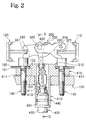
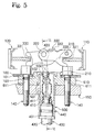
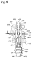
- the first embodiment of this invention as shown in Figure 1 is an example wherein the conventional spacer 600 and the guide pipe 500 are integrated.
- the pipe-like section 510 is integrally formed with the spacer 610.
- the pipe-like section 510 may be integrally formed with the spacer 610 by casting, forging, or aluminum die-cast, casting is the preferred method of integrating the pipe-like section 510 taking into account production and cost.
- the pipe-like section 510 is integrally extended from the end surface of the spacer 610 at the side of the brake mounting member 150, so that the operational reaction force while in the braking operation is supported by the spacer 610 via the pipe-like section 510. Accordingly, the anchor 200 only needs to have a strength to support the brake force, which enables a reduction of the anchor 200 size, thereby reducing the weight of the anchor 200. Further, there is no projection out from the anchor seat 202 of the anchor 200 at the side of the crank mechanism 300. This increases the extent of an effective stroke of the brake cable 400, thereby increasing its applicability when the brake off-set is small.
- the large diameter portion of the casing cap 431 of the outer casing 430 abuts against the outer opening end of the pipe-like section 510 and at the same time the small diameter portion of the casing cap 431 fits into the hole of the pipe-like section 510.
- the brake cable 400 is then retained on the pipe-like section 510 by the clip 440.
- the brake cable 400 does not come out after properly positioning the other side of the brake cable 400, i.e., the driver's side of the brake cable 400, on the corresponding member, i.g., a hand brake positioned next to the driver's seat.
- the casing cap 431 may be press fit into the hole of the pipe-like section 510 instead of using the clip 440.
- the diameter of a through hole 203 formed on the anchor seat 202 of the anchor 200 only needs to be just large enough to have the cable end nipple 420 and the inner cable 410 pass through thereby further reducing the size of the anchor seat 202.
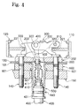
- This second embodiment illustrates the case where the anchor section 210 is integrally formed with the spacer 610 in addition to the pipe-like section 510 as in embodiment 1.
- the anchor section 210 penetrates through holes 102, 103 of the back plate 100 and the stiffener 101 and is extended to support both brake shoes 110, 120.
- the number of components necessary for the structure is reduced and nearly the same effectiveness as obtained by the first embodiment is achieved.
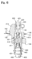
- the third embodiment illustrates the concept or notion where the guide pipe 500 is integrated with the spacer 600.
- a large diameter overhanging portion in this embodiment can be formed by welding a washer on the guide pipe 500 instead of the conventional overhanging portion 501 integrally formed on the guide pipe 500. Therefore, the guide pipe 500 is integrated with the spacer 600.
- this third embodiment enables an increase in the effective stroke of the brake cable 400 and a decrease of the size of the anchor 200.
- Embodiments 1-4 show a brake cable mounting structure for a duo-servo (DS) type drum brake where one adjacent facing end of the pair of brake shoes 110, 120 is supported by the anchor 200, and the other adjacent facing end of the brake shoes 110, 120 is connected via the adjuster 130.
- this invention is not limited to what is described above.
- the brake cable mounting structure of this invention is applicable to a leading trailing (LT) type drum brake where a fixed anchor instead of the adjuster 130 as in the conventional art of Figure 7 is employed as shown in German Utility Model Publication Number 7116427. As shown in the U.S.
- Patent Number 5720367 this invention is also applicable to the dual-mode drum brake which functions as a LT type when in service brake operation and functions as a DS type when in parking brake operation. It is sufficient if, at a minimum, the brake cable mounting structure for the drum brake has a crank mechanism 300 and a pipe-like section 510 or guide pipe 500.
Abstract
Description
Claims (7)
- A brake cable mounting structure for a drum brake comprising:a crank mechanism (300) having an input force portion (322), said crank mechanism (300) being disposed adjacent to a pair of adjacent facing ends of brake shoes (110,120) moveably mounted on a back plate (100) so as to actuate said brake shoes (110,120);a brake cable (400) having an inner cable (410) and an outer casing (430), said inner cable (410) being connected with said input force portion (322) of said crank mechanism (300); anda pipe member (500;510) for guiding said inner cable (410) to pass out of said drum brake, said outer casing (430) being attached to said pipe member (500;510),wherein a part of the back plate (100) adjacent to said crank mechanism (300) is fixed on a brake mounting member (150) via a spacer (600;610), andsaid pipe member (500;510) is integrally formed with said spacer (600;610).
- The brake cable mounting structure for a drum brake as claimed in claim 1, wherein said pipe member (510) is integrated with said spacer (610) by casting.
- The brake cable mounting structure for a drum brake as claimed in claim 1, wherein said guide member is formed as a guid pipe (500).
- The brake cable mounting structure for a drum brake as claimed in claim 3, wherein a large diameter portion (501) provided at an intermediate portion of said guide pipe (500) abuts against a surface of said spacer (600) at a side of said brake mounting member (150),said guide pipe (500) defines a hollow funnel shape, with an open funnel end (502), andsaid spacer (600) is caught between said open funnel end (502) and said large diameter portion (501) to integrate said guide pipe (500) with said spacer (600).
- The brake cable mounting structure for a drum brake as claimed in claim 1 or 3, wherein an anchor member (200;210) supporting said pair of facing ends of said brake shoes (110,120) is positioned adjacent to said crank mechanism (300).
- The brake cable mounting structure for a drum brake as claimed in claim 5, wherein said anchor member (210) is integrally formed with said spacer (610).
- The brake cable mounting structure for a drum brake as claimed in claim 6, wherein said anchor member is integrated with said spacer by casting.
Applications Claiming Priority (2)
| Application Number | Priority Date | Filing Date | Title |
|---|---|---|---|
| JP35516299 | 1999-12-14 | ||
| JP35516299A JP2001165209A (en) | 1999-12-14 | 1999-12-14 | Brake cable fitting device for drum brake |
Publications (2)
| Publication Number | Publication Date |
|---|---|
| EP1108916A2 true EP1108916A2 (en) | 2001-06-20 |
| EP1108916A3 EP1108916A3 (en) | 2002-01-02 |
Family
ID=18442309
Family Applications (1)
| Application Number | Title | Priority Date | Filing Date |
|---|---|---|---|
| EP00127159A Withdrawn EP1108916A3 (en) | 1999-12-14 | 2000-12-12 | Brake cable mounting structure for a drum brake |
Country Status (3)
| Country | Link |
|---|---|
| US (1) | US6325183B2 (en) |
| EP (1) | EP1108916A3 (en) |
| JP (1) | JP2001165209A (en) |
Families Citing this family (6)
| Publication number | Priority date | Publication date | Assignee | Title |
|---|---|---|---|---|
| JP4794723B2 (en) * | 2000-07-17 | 2011-10-19 | 日清紡ホールディングス株式会社 | Brake cable connection device |
| JP2002266909A (en) * | 2001-03-06 | 2002-09-18 | Nisshinbo Ind Inc | Brake cable fitting device for drum brake |
| US6679354B1 (en) * | 2003-01-28 | 2004-01-20 | Robert Bosch Corporation | Actuator mechanism for drum in hat brake |
| DE102011110975B4 (en) * | 2011-03-17 | 2015-08-13 | Volkswagen Aktiengesellschaft | Power transmission element with a traction means movable in a shell, whose transition region is enclosed by a flexible bellows, and such a bellows |
| DE102017214938B4 (en) * | 2016-08-31 | 2020-09-03 | Mando Corporation | Electronic parking brake |
| IT201600105859A1 (en) * | 2016-10-20 | 2018-04-20 | Freni Brembo Spa | Implementation assembly of a parking brake |
Citations (3)
| Publication number | Priority date | Publication date | Assignee | Title |
|---|---|---|---|---|
| DE7116427U (en) | 1971-08-19 | Bergische Achsenfabrik Kotz & Soehne | Drum brake with spreading lever to tension | |
| JPH06337027A (en) | 1993-05-27 | 1994-12-06 | Nisshinbo Ind Inc | Mechanical drum brake device |
| US5720367A (en) | 1995-08-23 | 1998-02-24 | Kelsey-Hayes Company | Parking and emergency brake operating mechanism for dual mode drum brake assemlby |
Family Cites Families (9)
| Publication number | Priority date | Publication date | Assignee | Title |
|---|---|---|---|---|
| GB496383A (en) * | 1937-03-25 | 1938-11-25 | Bendix Aviat Corp | Improvements in applying means for brakes |
| GB1383754A (en) * | 1971-04-27 | 1974-02-12 | Girling Ltd | Cross-pull brake actuator |
| JPS5112063A (en) * | 1974-07-17 | 1976-01-30 | Tokico Ltd | Bureekishuuno kangekijidochoseisochi |
| DE3428135A1 (en) | 1984-07-31 | 1986-02-13 | Alfred Teves Gmbh, 6000 Frankfurt | INNER JAW BRAKE |
| DE3428134C2 (en) | 1984-07-31 | 1994-03-31 | Teves Gmbh Alfred | Brake cable attachment |
| US5322145A (en) * | 1989-08-29 | 1994-06-21 | Kelsey-Hayes Company | Drum brake operating mechanism |
| JP3146400B2 (en) * | 1993-06-24 | 2001-03-12 | 日清紡績株式会社 | Cable connection method for drum brake |
| DE4327557B4 (en) | 1993-08-17 | 2004-08-26 | Continental Teves Ag & Co. Ohg | Duo-servo parking brake for motor vehicles |
| US5529149A (en) * | 1994-11-21 | 1996-06-25 | Alliedsignal Inc. | Drum-in-hat brake with reverse scissors actuator |
-
1999
- 1999-12-14 JP JP35516299A patent/JP2001165209A/en not_active Withdrawn
-
2000
- 2000-12-04 US US09/727,467 patent/US6325183B2/en not_active Expired - Fee Related
- 2000-12-12 EP EP00127159A patent/EP1108916A3/en not_active Withdrawn
Patent Citations (3)
| Publication number | Priority date | Publication date | Assignee | Title |
|---|---|---|---|---|
| DE7116427U (en) | 1971-08-19 | Bergische Achsenfabrik Kotz & Soehne | Drum brake with spreading lever to tension | |
| JPH06337027A (en) | 1993-05-27 | 1994-12-06 | Nisshinbo Ind Inc | Mechanical drum brake device |
| US5720367A (en) | 1995-08-23 | 1998-02-24 | Kelsey-Hayes Company | Parking and emergency brake operating mechanism for dual mode drum brake assemlby |
Also Published As
| Publication number | Publication date |
|---|---|
| US20010037918A1 (en) | 2001-11-08 |
| JP2001165209A (en) | 2001-06-19 |
| EP1108916A3 (en) | 2002-01-02 |
| US6325183B2 (en) | 2001-12-04 |
Similar Documents
| Publication | Publication Date | Title |
|---|---|---|
| KR100493583B1 (en) | Drum brake device | |
| EP1108916A2 (en) | Brake cable mounting structure for a drum brake | |
| US6412609B2 (en) | Brake cable mounting structure for a drum brake | |
| EP1174627B1 (en) | Brake cable connecting apparatus for drum brake | |
| JPH11117965A (en) | Drum brake device | |
| US6742633B1 (en) | Linkage for joining a lever to a brake cable | |
| US6766887B2 (en) | Dual mode type drum brake device | |
| JP4672130B2 (en) | Drum brake with automatic shoe clearance adjustment mechanism | |
| JP3936731B2 (en) | Electric drum brake | |
| JP3413459B2 (en) | Drum brake device | |
| US6390248B1 (en) | Dual mode drum brake device | |
| JP4354604B2 (en) | Brake cable attachment device for drum brake | |
| JP3660507B2 (en) | Disc brake | |
| JP3551222B2 (en) | Drum brake anchor device | |
| JP2001159437A (en) | Drum brake device | |
| JP4597345B2 (en) | Drum brake | |
| JP3554949B2 (en) | Drum brake device | |
| JP2002266909A (en) | Brake cable fitting device for drum brake | |
| KR20020089073A (en) | Drum brake | |
| JP3553590B2 (en) | Drum brake actuator | |
| JP4530594B2 (en) | Brake device cable introduction structure | |
| US20030024779A1 (en) | Dual-mode drum brake assembly having provision for preventing disengagement of members to be mutually engaged | |
| JPS634663Y2 (en) | ||
| JPS639789Y2 (en) | ||
| JP2003314594A (en) | Drum brake device |
Legal Events
| Date | Code | Title | Description |
|---|---|---|---|
| PUAI | Public reference made under article 153(3) epc to a published international application that has entered the european phase |
Free format text: ORIGINAL CODE: 0009012 |
|
| AK | Designated contracting states |
Kind code of ref document: A2 Designated state(s): AT BE CH CY DE DK ES FI FR GB GR IE IT LI LU MC NL PT SE TR |
|
| AX | Request for extension of the european patent |
Free format text: AL;LT;LV;MK;RO;SI |
|
| PUAL | Search report despatched |
Free format text: ORIGINAL CODE: 0009013 |
|
| AK | Designated contracting states |
Kind code of ref document: A3 Designated state(s): AT BE CH CY DE DK ES FI FR GB GR IE IT LI LU MC NL PT SE TR |
|
| AX | Request for extension of the european patent |
Free format text: AL;LT;LV;MK;RO;SI |
|
| RIC1 | Information provided on ipc code assigned before grant |
Free format text: 7F 16D 65/09 A, 7F 16D 65/22 B |
|
| 17P | Request for examination filed |
Effective date: 20020607 |
|
| AKX | Designation fees paid | ||
| RBV | Designated contracting states (corrected) |
Designated state(s): DE GB |
|
| REG | Reference to a national code |
Ref country code: DE Ref legal event code: 8566 |
|
| STAA | Information on the status of an ep patent application or granted ep patent |
Free format text: STATUS: THE APPLICATION IS DEEMED TO BE WITHDRAWN |
|
| 18D | Application deemed to be withdrawn |
Effective date: 20040701 |