EP1447520B1 - Accessoire d'échelle - Google Patents
Accessoire d'échelle Download PDFInfo
- Publication number
- EP1447520B1 EP1447520B1 EP20040100469 EP04100469A EP1447520B1 EP 1447520 B1 EP1447520 B1 EP 1447520B1 EP 20040100469 EP20040100469 EP 20040100469 EP 04100469 A EP04100469 A EP 04100469A EP 1447520 B1 EP1447520 B1 EP 1447520B1
- Authority
- EP
- European Patent Office
- Prior art keywords
- ladder
- stiles
- accessory
- extension
- rails
- Prior art date
- Legal status (The legal status is an assumption and is not a legal conclusion. Google has not performed a legal analysis and makes no representation as to the accuracy of the status listed.)
- Expired - Lifetime
Links
- 230000007246 mechanism Effects 0.000 claims description 10
- 230000000717 retained effect Effects 0.000 description 2
- 238000010276 construction Methods 0.000 description 1
- 238000004519 manufacturing process Methods 0.000 description 1
Images


Classifications
-
- E—FIXED CONSTRUCTIONS
- E06—DOORS, WINDOWS, SHUTTERS, OR ROLLER BLINDS IN GENERAL; LADDERS
- E06C—LADDERS
- E06C1/00—Ladders in general
- E06C1/02—Ladders in general with rigid longitudinal member or members
- E06C1/04—Ladders for resting against objects, e.g. walls poles, trees
- E06C1/08—Ladders for resting against objects, e.g. walls poles, trees multi-part
- E06C1/12—Ladders for resting against objects, e.g. walls poles, trees multi-part extensible, e.g. telescopic
- E06C1/125—Ladders for resting against objects, e.g. walls poles, trees multi-part extensible, e.g. telescopic with tubular longitudinal members nested within each other
-
- E—FIXED CONSTRUCTIONS
- E06—DOORS, WINDOWS, SHUTTERS, OR ROLLER BLINDS IN GENERAL; LADDERS
- E06C—LADDERS
- E06C1/00—Ladders in general
- E06C1/02—Ladders in general with rigid longitudinal member or members
- E06C1/04—Ladders for resting against objects, e.g. walls poles, trees
- E06C1/08—Ladders for resting against objects, e.g. walls poles, trees multi-part
- E06C1/10—Sections fitted end to end
-
- E—FIXED CONSTRUCTIONS
- E06—DOORS, WINDOWS, SHUTTERS, OR ROLLER BLINDS IN GENERAL; LADDERS
- E06C—LADDERS
- E06C1/00—Ladders in general
- E06C1/02—Ladders in general with rigid longitudinal member or members
- E06C1/14—Ladders capable of standing by themselves
- E06C1/16—Ladders capable of standing by themselves with hinged struts which rest on the ground
- E06C1/20—Ladders capable of standing by themselves with hinged struts which rest on the ground with supporting struts formed as poles
- E06C1/22—Ladders capable of standing by themselves with hinged struts which rest on the ground with supporting struts formed as poles with extensible, e.g. telescopic, ladder parts or struts
-
- E—FIXED CONSTRUCTIONS
- E06—DOORS, WINDOWS, SHUTTERS, OR ROLLER BLINDS IN GENERAL; LADDERS
- E06C—LADDERS
- E06C7/00—Component parts, supporting parts, or accessories
- E06C7/14—Holders for pails or other equipment on or for ladders
-
- E—FIXED CONSTRUCTIONS
- E06—DOORS, WINDOWS, SHUTTERS, OR ROLLER BLINDS IN GENERAL; LADDERS
- E06C—LADDERS
- E06C7/00—Component parts, supporting parts, or accessories
- E06C7/42—Ladder feet; Supports therefor
-
- E—FIXED CONSTRUCTIONS
- E06—DOORS, WINDOWS, SHUTTERS, OR ROLLER BLINDS IN GENERAL; LADDERS
- E06C—LADDERS
- E06C7/00—Component parts, supporting parts, or accessories
- E06C7/48—Ladder heads; Supports for heads of ladders for resting against objects
Definitions
- the present invention relates to a ladder and is particularly though not exclusively applicable to a telescopically collapsible ladder.
- This collapsible ladder comprises two stiles formed of telescopically collapsible sections, the lower end of each section fitting within the next lower section. Rungs are mounted each between two sections of the respective stiles, and latch mechanisms located in the rungs automatically lock the sections of the stiles relative to one another when the sections are extended. The latch mechanisms in each rung are arranged to release the sections of the stiles connected to the next higher rung when the rung is collapsed against the next lower rung. Because of this construction, when the lowermost rung is collapsed, it causes the entire ladder to collapse one section at a time.
- the present invention seeks to provide a ladder with an accessory that enables a person standing on one of the rungs of the ladder to reach higher without impairing the safety of the ladder.
- a ladder in combination with an accessory which comprises a pair of telescopically collapsible extension stiles connected as extensions of the stiles of the ladder, a stand-off frame secured to the lower end of the extension stiles for distancing the top of the ladder from a wall against which the ladder is leaned and at least one rail extending between the extension stiles.
- the stand-off frame is preferably pivotable relative to the extension stiles so that it may be folded to lie parallel to the plane of the extension stiles for convenient storage.
- the accessory in the same manner as a ladder with rails instead of rungs connected between respect pairs of sections of the collapsible stiles.
- the rails need not and preferably should not be strong enough to support the weight of a person as they should not be stood upon. However, the rails may be formed as shelves to support tools.
- a self-supporting collapsible ladder somewhat similar to the ladder accessory of the preferred embodiment of the invention is described in US 5,645,140 .
- This ladder unlike the ladder of the invention, is not designed to be leaned on a wall but instead its equivalent of a stand-off frame is intended to act as a base that rests on the ground and supports the entire weight of the ladder.
- the stiles of the ladder are thus designed to rest on the ground and cannot be fitted as an extension of the stiles of another ladder.
- the ladder has strong rungs intended to support the weight of a person whereas in the preferred embodiment of the invention the rails of the accessory are not meant to be stood upon, only to support tools.
- the rails have holes for receiving and locating tools. If aligned holes are formed in several rails, then they can be used to hold tools even when the accessory is not fully extended.
- the standoff frame may be provided with retractable lateral extensions to contact the wall at locations further apart than the width of the ladder.
- Such lateral extensions may suitably be resiliently biased apart into their extended positions and held in their retracted position by means of pins that are automatically released when the stand off frame is pivoted to its horizontal position.
- a ladder accessory 10 comprises two telescopically collapsible stiles 12 and 14. Rails extend between the sections of the stiles, the top rail 18 being designed as a handrail and the remaining rails 16 being formed as shelves that are not strong enough to support the weight of a person.
- the lower rails 16 are instead contoured to enable tools to be placed on them without risk of sliding off.
- the lower rails are also provided with holes 19 for receiving tools such as screwdrivers and the holes 19 in the different rails are in alignment so that they can be used to hold tools even when the accessory 10 is not fully extended, as shown in Figure 2 .
- a stand-off frame 20 is secured to the two lowermost sections of the stiles 12 and 14.
- the frame 20 is pivotable relative to the stiles about a pivot 22 between a storage position, shown in Figure 2 , and an operating position, shown in Figure 1 .
- FIGs 3 and 4 The manner in which the accessory 10 is used is best shown in Figures 3 and 4 .
- the stiles 12 and 14 are intended to act as extensions of the stiles of the ladder.
- Figure 3 shows that the accessory can be fitted to a Telesteps ladder 30 that is itself telescopically collapsible by plugging the lower ends of the stiles 12 and 14 directly into the top sections of the stiles of the ladder 30.
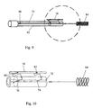
- a Telesteps ladder as shown in Figure 8 , has retractable pins 40 in its rungs 42 that are biased by springs 44 in a direction to lock the sections of the stiles to one another in their extended position.
- the upper rungs cannot be used because the person would be too close to the wall on which the ladder is leaning and because there would be no handrail to grip for safety.
- the preferred embodiment of the invention enables the higher rungs of the ladder to be used because its stand-off frame distances the top of the ladder from the wall and because it provides both a handrail and secure support surfaces for tools.
- the accessory does not however act as an extension of the ladder as its rails or shelves are not designed to support the weight of a person.
- the accessory is designed for use with a Telesteps ladder 30, it can be used with a conventional ladder as shown at 50 in Figure 4 .
- adapters 52 may be used, which are dimensioned to fit over the ends of the stiles of the ladder 50 and fit into (or to receive) the lower end of the stiles of the accessory 10.
- the stand-off frame 20 In its operating position, the stand-off frame 20 is designed to extend at right angles to the stiles and it is held in that position by a pair of articulated arms 60. Because the frame 20 is perpendicular to the stiles 12 and 14, the arms 60 are in tension while the ladder is in used and there is no tendency for the arms to fold into their storage position.
- the lateral ends of the stand-off frame 20 are provided with retractable extensions 62.
- the extensions 62 are urged into their extended position by springs 84 (see Figures 9 and 10 ) so that in use they project sideways to span a width greater than the width of the ladder. In this way, the extensions 62 act to steady the ladder and avoid any tendency for it to twist about its own longitudinal axis when it is in use.
- pins 64 are provided to hold the retractable extensions 62 in their retracted position when the accessory is folded for storage.
- the pins 64 are urged by means of springs 66 in a direction to engage holes 86 (see Figure 9 ) in the extensions 62 to lock the extensions in their retracted positions.
- the pins 64 are attached to cords 68 which are wrapped around the pivots 70 that connect the articulated arms 60 to the stand-off frame 20.
- the pins 64 are disengaged by the cords 68 from the holes in the extensions 62 so that the extensions are automatically deployed when the stand-off frame 20 is pivoted into its position perpendicular to the stiles of the ladder.
- the extensions can be retracted manually and will be retained in this position by the pins 64.
- the lateral extension 62 is formed of a tube having a longitudinally extending recess 72 in its surface and three holes 74, 76 and 86 all lying on the same line as the recess 72.
- the hole 86 receives the pin 64 that holds the extension 62 in its retracted position.
- the other two holes 74 and 76 serve to locate a bar 78, the axial end of which abuts the pin 64 when the extension 62 is in its extended position to prevent the extension 62 from coming away entirely.
- the bar 78 has two projecting prongs 80 and 82 that are received in the holes 76 and 74, respectively, to prevent the bar 78 from sliding along the recess 72.
- the prong 80 is as long as the diameter of the extension 62 so that it may also act as an abutment for the spring 84 that biases the extension 62 into its extended position.
- the hand rail 18 When the ladder is erected, it is possible for the hand rail 18 to be spaced from the wall but it is preferred that it should rest against the wall without taking the weight of the ladder.
- the hand rail may be positioned to rest on the wall with the stand-off frame 20 slightly spaced from the wall.
- the frame 20 comes into contact with the wall as the stiles of the ladder bend under the weight of the person. Thereafter the weight of the person is supported by the standoff frame 20 but because contact is made with the wall at several places, the stability of the ladder is significantly improved. In the unlikely event of the frame 20 giving way for any reason, the ladder will not collapse or move significantly, permitting the person standing on it to descend safely.
- the sections of the ladder accessory are preferably prevented from collapsing when in use by means of locking mechanisms constructed in the same manner as the locking mechanisms of the Telesteps ladder described above. This is desirable from the point of view of reducing manufacturing cost and ease of use.
- the accessory is itself relatively small and has few sections, it is not essential for it to collapse from the bottom upwards nor for its locking mechanism to be arranged on the underside of its rails to cause automatic release of the locking mechanisms as the rails come into contact with each other.
Claims (10)
- Échelle en combinaison avec un accessoire qui comprend une paire de montants d'extension se pliant ou s'escamotant de façon télescopique (12, 14), qui sont connectés en tant qu'extensions des montants de l'échelle (30 ; 50), une structure d'entretoise (20) attachée à l'extrémité inférieure des montants d'extension (12, 14) pour distancer ou espacer le sommet de l'échelle d'un mur contre lequel l'échelle est adossée et au moins un rail (18) qui s'étend entre les montants d'extension.
- Combinaison d'échelle et d'accessoire selon la revendication 1, dans laquelle la structure d'entretoise (20) est pivotante par rapport aux montants d'extension (12, 14), de sorte qu'elle repose de façon parallèle ou perpendiculaire au plan des montants d'extension (12, 14).
- Combinaison d'échelle et d'accessoire selon la revendication 1 ou 2, comprenant une pluralité de rails (16, 18) destinés à s'étendre de façon parallèle au barreaux de l'échelle (30 ; 50), chacun étant connecté entre une paire respective de sections des montants pliants (12, 14).
- Combinaison d'échelle et d'accessoire selon la revendication 3, dans laquelle les rails (16) sont formés comme des tablettes pour maintenir des outils.
- Combinaison d'échelle et d'accessoire selon la revendication 3 ou 4, dans laquelle dans laquelle les rails (16) possèdent des orifices (19) pour accommoder et disposer des outils.
- Combinaison d'échelle et d'accessoire selon la revendication 5, dans laquelle les orifices (19) sont formés dans plusieurs rails (16), les orifices (19) dans les différents rails (16) étant alignés.
- Combinaison d'échelle et d'accessoire selon l'une des revendications précédentes, dans laquelle la structure d'entretoise (20) est dotée d'extensions latérales parallèles (62) pour contacter avec la paroi au niveau d'endroits plus distants que la largeur de l'échelle.
- Combinaison d'échelle et d'accessoire selon la revendication 7, dans laquelle les extensions latérales parallèles (62) sont élastiquement rappelées à l'écart l'une de l'autre et vers leur position étendue, et sont maintenues dans leur position rétractée au moyen de goupilles (64) qui sont automatiquement libérées lorsque la structure d'entretoise (20) pivote par rapport à sa position horizontale.
- Combinaison d'échelle et d'accessoire selon l'une des revendications précédentes, dans laquelle des mécanismes de verrouillage sont fournis dans les rails de l'extension pour verrouiller les sections des montants l'une à l'autre dans leur position étendue.
- Combinaison d'échelle et d'accessoire selon la revendication 9, dans laquelle les mécanismes de verrouillage sont conçus de telle sorte que, au fur et à mesure du pliage descendant de chaque rail sur le prochain rail inférieur, les mécanismes de verrouillage pour les sections de montants connectées au prochain rail supérieur soient automatiquement libérés.
Applications Claiming Priority (4)
| Application Number | Priority Date | Filing Date | Title |
|---|---|---|---|
| GBGB0303010.3A GB0303010D0 (en) | 2003-02-11 | 2003-02-11 | Ladder accessory |
| GB0303010 | 2003-02-11 | ||
| GB0304461 | 2003-02-27 | ||
| GB0304461A GB2398339A (en) | 2003-02-11 | 2003-02-27 | Combined telescopic extension and stand off for ladder |
Publications (3)
| Publication Number | Publication Date |
|---|---|
| EP1447520A2 EP1447520A2 (fr) | 2004-08-18 |
| EP1447520A3 EP1447520A3 (fr) | 2005-05-11 |
| EP1447520B1 true EP1447520B1 (fr) | 2008-07-16 |
Family
ID=32683999
Family Applications (1)
| Application Number | Title | Priority Date | Filing Date |
|---|---|---|---|
| EP20040100469 Expired - Lifetime EP1447520B1 (fr) | 2003-02-11 | 2004-02-09 | Accessoire d'échelle |
Country Status (1)
| Country | Link |
|---|---|
| EP (1) | EP1447520B1 (fr) |
Families Citing this family (5)
| Publication number | Priority date | Publication date | Assignee | Title |
|---|---|---|---|---|
| FR2889240A1 (fr) * | 2005-08-01 | 2007-02-02 | Duarib Soc Par Actions Simplif | Stabilisateur pour appareil d'ascension |
| CN102199988B (zh) * | 2011-03-23 | 2013-03-13 | 李彩琴 | 具有轻便爬梯的加油装置 |
| US20150354276A1 (en) * | 2014-05-19 | 2015-12-10 | Lock N Climb, Llc | Collapsible ladder |
| CN107269217A (zh) * | 2017-06-12 | 2017-10-20 | 福建省连江乐鑫林业开发有限公司 | 一种靠底座自立防滑的单柱插接梯 |
| CN108590496B (zh) * | 2018-04-30 | 2019-07-26 | 南通北外滩建设工程有限公司 | 一种水利设备检修用登高梯 |
Family Cites Families (6)
| Publication number | Priority date | Publication date | Assignee | Title |
|---|---|---|---|---|
| US2881028A (en) | 1957-10-11 | 1959-04-07 | James D Baird | Ladder platform |
| GB845949A (en) * | 1958-06-14 | 1960-08-24 | Alistair Maclennan | Improvements in step ladders |
| FI73498C (fi) * | 1982-09-16 | 1987-10-09 | Birger O Mattsson | Hopvikbara steger. |
| AU643520B2 (en) | 1990-04-10 | 1993-11-18 | Pacific Ladder LLC | Collapsible ladder |
| US5503245A (en) * | 1994-09-16 | 1996-04-02 | Keller Industries, Inc. | Step ladder |
| US5645140A (en) * | 1995-05-08 | 1997-07-08 | Mouneimneh; Ghassoub A. | Self-supported collapsible ladder |
-
2004
- 2004-02-09 EP EP20040100469 patent/EP1447520B1/fr not_active Expired - Lifetime
Also Published As
| Publication number | Publication date |
|---|---|
| EP1447520A2 (fr) | 2004-08-18 |
| EP1447520A3 (fr) | 2005-05-11 |
Similar Documents
| Publication | Publication Date | Title |
|---|---|---|
| US10815728B2 (en) | Elevated working platform and related methods | |
| US5868222A (en) | Ladder stabilizers | |
| CN110891461B (zh) | 梯子铰链和结合有梯子铰链的梯子 | |
| US20090078503A1 (en) | Collapsible Platform | |
| EA012890B1 (ru) | Складная комбинированная лестница | |
| RU2008124808A (ru) | Складная платформа | |
| US4004393A (en) | Adjustable heighth shoring | |
| US10584532B2 (en) | Ladders with integrated support, ladder components and related methods | |
| US7255198B1 (en) | Tripod extension stepladder | |
| US20080164097A1 (en) | Collapsible Combination Ladder | |
| EP1696084A1 (fr) | Traverse télescopique apte à être utilisée comme garde-corps pour chevalets | |
| EP1447520B1 (fr) | Accessoire d'échelle | |
| CN114585795A (zh) | 梯子三脚架组件和系统 | |
| JP2005336987A (ja) | 作業用足場台及びこれを利用する連結足場台 | |
| JP4880026B2 (ja) | 作業用足場台及びこれを利用する連結足場台 | |
| JP4035485B2 (ja) | トラック用昇降梯子 | |
| GB2398339A (en) | Combined telescopic extension and stand off for ladder | |
| US4926964A (en) | Step/extension ladder | |
| GB2099059A (en) | Improvements in or relating to ladders | |
| EP2060735A1 (fr) | Échelle trépied à rallonges amovibles | |
| EP3867482B1 (fr) | Dispositif comprenant un système stabilisateur et une échelle pliable | |
| KR102588273B1 (ko) | 사다리와 결합하여 작업대로 사용 가능한 우마사다리 | |
| WO2023046760A1 (fr) | Échelle portable comportant un dispositif de recul | |
| WO1999051848A1 (fr) | Escabeau repliable | |
| CA3008296A1 (fr) | Echelle extensible ou droite comportant une plateforme retractable |
Legal Events
| Date | Code | Title | Description |
|---|---|---|---|
| PUAI | Public reference made under article 153(3) epc to a published international application that has entered the european phase |
Free format text: ORIGINAL CODE: 0009012 |
|
| AK | Designated contracting states |
Kind code of ref document: A2 Designated state(s): AT BE BG CH CY CZ DE DK EE ES FI FR GB GR HU IE IT LI LU MC NL PT RO SE SI SK TR |
|
| AX | Request for extension of the european patent |
Extension state: AL LT LV MK |
|
| PUAL | Search report despatched |
Free format text: ORIGINAL CODE: 0009013 |
|
| AK | Designated contracting states |
Kind code of ref document: A3 Designated state(s): AT BE BG CH CY CZ DE DK EE ES FI FR GB GR HU IE IT LI LU MC NL PT RO SE SI SK TR |
|
| AX | Request for extension of the european patent |
Extension state: AL LT LV MK |
|
| RIC1 | Information provided on ipc code assigned before grant |
Ipc: 7E 06C 7/48 A Ipc: 7E 06C 7/42 B Ipc: 7E 06C 7/14 B Ipc: 7E 06C 1/10 B Ipc: 7E 06C 1/12 B |
|
| 17P | Request for examination filed |
Effective date: 20051010 |
|
| AKX | Designation fees paid |
Designated state(s): AT BE BG CH CY CZ DE DK EE ES FI FR GB GR HU IE IT LI LU MC NL PT RO SE SI SK TR |
|
| 17Q | First examination report despatched |
Effective date: 20071120 |
|
| GRAP | Despatch of communication of intention to grant a patent |
Free format text: ORIGINAL CODE: EPIDOSNIGR1 |
|
| GRAS | Grant fee paid |
Free format text: ORIGINAL CODE: EPIDOSNIGR3 |
|
| GRAA | (expected) grant |
Free format text: ORIGINAL CODE: 0009210 |
|
| AK | Designated contracting states |
Kind code of ref document: B1 Designated state(s): AT BE BG CH CY CZ DE DK EE ES FI FR GB GR HU IE IT LI LU MC NL PT RO SE SI SK TR |
|
| REG | Reference to a national code |
Ref country code: GB Ref legal event code: FG4D |
|
| REG | Reference to a national code |
Ref country code: CH Ref legal event code: EP |
|
| REF | Corresponds to: |
Ref document number: 602004015004 Country of ref document: DE Date of ref document: 20080828 Kind code of ref document: P |
|
| REG | Reference to a national code |
Ref country code: IE Ref legal event code: FG4D |
|
| NLV1 | Nl: lapsed or annulled due to failure to fulfill the requirements of art. 29p and 29m of the patents act | ||
| PG25 | Lapsed in a contracting state [announced via postgrant information from national office to epo] |
Ref country code: ES Free format text: LAPSE BECAUSE OF FAILURE TO SUBMIT A TRANSLATION OF THE DESCRIPTION OR TO PAY THE FEE WITHIN THE PRESCRIBED TIME-LIMIT Effective date: 20081027 Ref country code: PT Free format text: LAPSE BECAUSE OF FAILURE TO SUBMIT A TRANSLATION OF THE DESCRIPTION OR TO PAY THE FEE WITHIN THE PRESCRIBED TIME-LIMIT Effective date: 20081216 Ref country code: NL Free format text: LAPSE BECAUSE OF FAILURE TO SUBMIT A TRANSLATION OF THE DESCRIPTION OR TO PAY THE FEE WITHIN THE PRESCRIBED TIME-LIMIT Effective date: 20080716 |
|
| PG25 | Lapsed in a contracting state [announced via postgrant information from national office to epo] |
Ref country code: SI Free format text: LAPSE BECAUSE OF FAILURE TO SUBMIT A TRANSLATION OF THE DESCRIPTION OR TO PAY THE FEE WITHIN THE PRESCRIBED TIME-LIMIT Effective date: 20080716 Ref country code: BG Free format text: LAPSE BECAUSE OF FAILURE TO SUBMIT A TRANSLATION OF THE DESCRIPTION OR TO PAY THE FEE WITHIN THE PRESCRIBED TIME-LIMIT Effective date: 20081016 Ref country code: FI Free format text: LAPSE BECAUSE OF FAILURE TO SUBMIT A TRANSLATION OF THE DESCRIPTION OR TO PAY THE FEE WITHIN THE PRESCRIBED TIME-LIMIT Effective date: 20080716 Ref country code: AT Free format text: LAPSE BECAUSE OF FAILURE TO SUBMIT A TRANSLATION OF THE DESCRIPTION OR TO PAY THE FEE WITHIN THE PRESCRIBED TIME-LIMIT Effective date: 20080716 |
|
| PG25 | Lapsed in a contracting state [announced via postgrant information from national office to epo] |
Ref country code: BE Free format text: LAPSE BECAUSE OF FAILURE TO SUBMIT A TRANSLATION OF THE DESCRIPTION OR TO PAY THE FEE WITHIN THE PRESCRIBED TIME-LIMIT Effective date: 20080716 |
|
| PG25 | Lapsed in a contracting state [announced via postgrant information from national office to epo] |
Ref country code: DK Free format text: LAPSE BECAUSE OF FAILURE TO SUBMIT A TRANSLATION OF THE DESCRIPTION OR TO PAY THE FEE WITHIN THE PRESCRIBED TIME-LIMIT Effective date: 20080716 Ref country code: EE Free format text: LAPSE BECAUSE OF FAILURE TO SUBMIT A TRANSLATION OF THE DESCRIPTION OR TO PAY THE FEE WITHIN THE PRESCRIBED TIME-LIMIT Effective date: 20080716 |
|
| PLBE | No opposition filed within time limit |
Free format text: ORIGINAL CODE: 0009261 |
|
| STAA | Information on the status of an ep patent application or granted ep patent |
Free format text: STATUS: NO OPPOSITION FILED WITHIN TIME LIMIT |
|
| PG25 | Lapsed in a contracting state [announced via postgrant information from national office to epo] |
Ref country code: RO Free format text: LAPSE BECAUSE OF FAILURE TO SUBMIT A TRANSLATION OF THE DESCRIPTION OR TO PAY THE FEE WITHIN THE PRESCRIBED TIME-LIMIT Effective date: 20080716 Ref country code: CZ Free format text: LAPSE BECAUSE OF FAILURE TO SUBMIT A TRANSLATION OF THE DESCRIPTION OR TO PAY THE FEE WITHIN THE PRESCRIBED TIME-LIMIT Effective date: 20080716 Ref country code: SK Free format text: LAPSE BECAUSE OF FAILURE TO SUBMIT A TRANSLATION OF THE DESCRIPTION OR TO PAY THE FEE WITHIN THE PRESCRIBED TIME-LIMIT Effective date: 20080716 |
|
| 26N | No opposition filed |
Effective date: 20090417 |
|
| PGFP | Annual fee paid to national office [announced via postgrant information from national office to epo] |
Ref country code: GB Payment date: 20090330 Year of fee payment: 6 |
|
| PG25 | Lapsed in a contracting state [announced via postgrant information from national office to epo] |
Ref country code: IT Free format text: LAPSE BECAUSE OF FAILURE TO SUBMIT A TRANSLATION OF THE DESCRIPTION OR TO PAY THE FEE WITHIN THE PRESCRIBED TIME-LIMIT Effective date: 20080716 |
|
| PG25 | Lapsed in a contracting state [announced via postgrant information from national office to epo] |
Ref country code: MC Free format text: LAPSE BECAUSE OF NON-PAYMENT OF DUE FEES Effective date: 20090228 |
|
| REG | Reference to a national code |
Ref country code: CH Ref legal event code: PL |
|
| PG25 | Lapsed in a contracting state [announced via postgrant information from national office to epo] |
Ref country code: LI Free format text: LAPSE BECAUSE OF NON-PAYMENT OF DUE FEES Effective date: 20090228 Ref country code: CH Free format text: LAPSE BECAUSE OF NON-PAYMENT OF DUE FEES Effective date: 20090228 |
|
| REG | Reference to a national code |
Ref country code: IE Ref legal event code: MM4A |
|
| REG | Reference to a national code |
Ref country code: FR Ref legal event code: ST Effective date: 20091030 |
|
| PGFP | Annual fee paid to national office [announced via postgrant information from national office to epo] |
Ref country code: DE Payment date: 20090722 Year of fee payment: 6 |
|
| PG25 | Lapsed in a contracting state [announced via postgrant information from national office to epo] |
Ref country code: SE Free format text: LAPSE BECAUSE OF FAILURE TO SUBMIT A TRANSLATION OF THE DESCRIPTION OR TO PAY THE FEE WITHIN THE PRESCRIBED TIME-LIMIT Effective date: 20081016 Ref country code: IE Free format text: LAPSE BECAUSE OF NON-PAYMENT OF DUE FEES Effective date: 20090209 |
|
| PG25 | Lapsed in a contracting state [announced via postgrant information from national office to epo] |
Ref country code: FR Free format text: LAPSE BECAUSE OF NON-PAYMENT OF DUE FEES Effective date: 20090302 |
|
| GBPC | Gb: european patent ceased through non-payment of renewal fee |
Effective date: 20100209 |
|
| PG25 | Lapsed in a contracting state [announced via postgrant information from national office to epo] |
Ref country code: GR Free format text: LAPSE BECAUSE OF FAILURE TO SUBMIT A TRANSLATION OF THE DESCRIPTION OR TO PAY THE FEE WITHIN THE PRESCRIBED TIME-LIMIT Effective date: 20081017 |
|
| PG25 | Lapsed in a contracting state [announced via postgrant information from national office to epo] |
Ref country code: DE Free format text: LAPSE BECAUSE OF NON-PAYMENT OF DUE FEES Effective date: 20100901 |
|
| PG25 | Lapsed in a contracting state [announced via postgrant information from national office to epo] |
Ref country code: GB Free format text: LAPSE BECAUSE OF NON-PAYMENT OF DUE FEES Effective date: 20100209 |
|
| PG25 | Lapsed in a contracting state [announced via postgrant information from national office to epo] |
Ref country code: LU Free format text: LAPSE BECAUSE OF NON-PAYMENT OF DUE FEES Effective date: 20090209 |
|
| PG25 | Lapsed in a contracting state [announced via postgrant information from national office to epo] |
Ref country code: HU Free format text: LAPSE BECAUSE OF FAILURE TO SUBMIT A TRANSLATION OF THE DESCRIPTION OR TO PAY THE FEE WITHIN THE PRESCRIBED TIME-LIMIT Effective date: 20090117 |
|
| PG25 | Lapsed in a contracting state [announced via postgrant information from national office to epo] |
Ref country code: TR Free format text: LAPSE BECAUSE OF FAILURE TO SUBMIT A TRANSLATION OF THE DESCRIPTION OR TO PAY THE FEE WITHIN THE PRESCRIBED TIME-LIMIT Effective date: 20080716 |
|
| PG25 | Lapsed in a contracting state [announced via postgrant information from national office to epo] |
Ref country code: CY Free format text: LAPSE BECAUSE OF FAILURE TO SUBMIT A TRANSLATION OF THE DESCRIPTION OR TO PAY THE FEE WITHIN THE PRESCRIBED TIME-LIMIT Effective date: 20080716 |