EP1447310A2 - Kraftfahrzeugbauteil - Google Patents
Kraftfahrzeugbauteil Download PDFInfo
- Publication number
- EP1447310A2 EP1447310A2 EP03026291A EP03026291A EP1447310A2 EP 1447310 A2 EP1447310 A2 EP 1447310A2 EP 03026291 A EP03026291 A EP 03026291A EP 03026291 A EP03026291 A EP 03026291A EP 1447310 A2 EP1447310 A2 EP 1447310A2
- Authority
- EP
- European Patent Office
- Prior art keywords
- sheet metal
- threaded connection
- profile
- opening
- metal profile
- Prior art date
- Legal status (The legal status is an assumption and is not a legal conclusion. Google has not performed a legal analysis and makes no representation as to the accuracy of the status listed.)
- Granted
Links
Images
Classifications
-
- B—PERFORMING OPERATIONS; TRANSPORTING
- B62—LAND VEHICLES FOR TRAVELLING OTHERWISE THAN ON RAILS
- B62D—MOTOR VEHICLES; TRAILERS
- B62D27/00—Connections between superstructure or understructure sub-units
- B62D27/06—Connections between superstructure or understructure sub-units readily releasable
- B62D27/065—Connections between superstructure or understructure sub-units readily releasable using screwthread
-
- B—PERFORMING OPERATIONS; TRANSPORTING
- B62—LAND VEHICLES FOR TRAVELLING OTHERWISE THAN ON RAILS
- B62D—MOTOR VEHICLES; TRAILERS
- B62D21/00—Understructures, i.e. chassis frame on which a vehicle body may be mounted
- B62D21/09—Means for mounting load bearing surfaces
Definitions
- the invention relates to a motor vehicle component made from a sheet metal profile at least one threaded connection.
- Breakthroughs that are made in the output board are after the Forming too imprecise due to the required tolerances.
- weld nuts or weld studs will bring these breakthroughs therefore out of the question.
- the components to process after forming for example by introducing the Breakthroughs with the help of laser cutting or an additional calibration and hole level in the tool.
- additional steps are capital-intensive because additional work steps, expensive laser processing and larger presses are necessary. This results in higher unit prices of Motor vehicle components.
- due to the high wear the punch and the calibration levels the maintenance effort and the Maintenance costs increased or tool life reduced.
- the invention is therefore based on the object of a motor vehicle component Sheet metal profile with threaded connection to design and a more economical to demonstrate a rational process for its production.
- the solution to the objective part of the task is one Motor vehicle component according to the features of claim 1.
- At least one opening is provided in the sheet metal profile, which through a washer body with a threaded connection is covered, with the disc body facing the opening has greater extension and on the edge surrounding the opening the sheet metal profile is overlapped.
- the threaded connection can be a threaded nut or act a threaded bolt.
- the breakthrough is already on the output board Printed circuit board trimmed.
- the dimensioning of the breakthrough can be done in this way be interpreted that all expected tolerances during the Production of the sheet metal profile can arise are taken into account.
- the Disk body has the threaded connection and is in its dimensions, in terms of the lateral extension, larger than the opening executed.
- the disc body completely covers the opening and is overlapping with the sheet metal profile at the edge surrounding the opening together.
- the washer body with the threaded connection can therefore meet the component requirements positioned fairly and automatically added.
- the exact The thread connection is positioned during the joining process. Any Tolerances or inaccuracies from the forming process become balanced.
- the welding is preferably determined by welding Disk body. In principle, other joining methods are also possible, for example an adhesive connection.
- the disc body is plate-shaped configured.
- the edge of the disc body can be continuous or else be interrupted. With the edge, the pane body is on the sheet metal profile together.
- the plate-shaped design enables a particularly advantageous Orientation relative to the sheet profile in a positioning unit.
- connection between the washer body and the threaded connection can also be designed differently. According to claim 3 it is provided that the threaded connection is welded to the washer body is.
- the solution to the procedural part of the problem is in claim 4 demonstrated.
- the sheet profile is made in one or more operations Made from a blank by press molding. Already in the output board when cutting blanks or on a semi-finished product or preform or an opening is created in the sheet profile.
- the dimensioning of the Breakthrough is sufficiently large that all possible in the manufacturing process occurring tolerances are taken into account.
- a Subsequent joining operation is the opening of a disk body covered, which has a threaded connection.
- the disk body is dimensioned in its extension so that it has the opening overlap on the edge and can be added to the profile here.
- the positioning of the disc body with the threaded connection on the Sheet metal profile can be hydraulic, for example, in a positioning unit be performed. The joining process can then take place.
- the disk body is preferably welded to the Sheet profile.
- the procedure according to the invention is basically for hot and cold Formed sheet metal profiles applicable.
- Process related benefits such as reduced tooling, fixture and tooling Machine costs as well as a longer tool life given both in cold forming and in hot forming.
- thermoformed components noticeable.
- the sheet profile is thermoformed and hardened, after which the disc body is then added.
- the disc body is then added.
- joining processes for the It is possible to fix the disc body to the sheet metal profile.
- the disk body is expediently replaced by a Positioning unit oriented, as provided in claim 6.
- the Positioning unit is the disc body together with the threaded connection positively received and in its component-specific position on Sheet profile positioned. Then the disc body with the Sheet metal profile connected. The position of the threaded connection is exactly in the position required for the further use of the motor vehicle component established.
- the positioning unit for the threaded connection to integrate with in the tool stages of the thermoforming tool.
- the prefabricated units consisting of threaded connection and washer body introduced via a feed unit and then during in the thermoforming tool the forming or in a corresponding chronological and logical order Positioned and fixed on the sheet metal profile.
- the disc body at Joining process is shear-formed in some areas.
- the disc body is in held by a positioning unit and positioned correctly on the profile component in the area positioned the breakthrough.
- a lower die unit supports this Sheet metal profile and the disc body, while an upper stamp unit grips, positions, and the disk body with the threaded connection reshapes.
- the disc body is then held in this way with the sheet metal profile joined, preferably by means of resistance welding.
- the motor vehicle component according to the invention is rational in production and inexpensive. Through the manufacturing process described Tool, fixture and machine costs can be reduced. The Tolerance field for attachments is reduced because the only tolerances for the Threaded connections (threaded bolts, threaded nuts) that the positioning unit are.
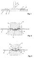
- Figures 1 to 3 each show a section of a motor vehicle component.
- the motor vehicle components are made from a sheet metal profile 1, 2, 3 and have at least one threaded connection 4, 5, 6.
- Each sheet profile 1, 2 or 3 is in one or more operations Made from a blank by press molding.
- the sheet metal profiles 1, 2, 3 at least one opening 7 is provided. This can be on the output board, be produced on a semi-finished product or on the finished sheet profile 1, 2, 3.
- the opening 7 in an output board is particularly advantageous hardenable steel. This then becomes warm in a press tool formed at a temperature between 700 ° C and 1,100 ° C. Yet The sheet profile 1, 2, 3 is then clamped in the press tool rapid cooling hardened while the sheet profile 1, 2, 3 in the press tool remains. Since the sheet profile 1, 2, 3 in the course of the hardening process cooling is clamped in the press tool one a sheet profile 1, 2, 3 with good dimensional accuracy.
- the opening 7 of a disc body 8, 9, 10 covered, which with the threaded connection 4, 5, 6 is provided.
- the disc body 8, 9, 10 has one opposite Opening 7 circumferentially larger extension 11 and is the Opening 7 surrounding edge 12 with the sheet profile 1, 2, 3 overlapping together.
- the threaded connection 4 or 6 is, as in FIGS. 1 and 3 shown to be a threaded bolt with an external thread 13.
- the threaded connection 5 is a through-threaded nut 14 as shown in FIG.
- the threaded connections 4, 5, 6 themselves are with the washer body 8, 9, 10 welded, especially friction welded.
- the type of indirect joining of the Disk body 8, 9, 10 can with larger tolerances in the sheet profile 1, 2, 3rd be worked. This enables the openings 7 to be introduced already in Platinenberough.
- the openings 7 can be designed so that all Tolerances to be expected are those during the manufacture of the sheet metal profile 1, 2, 3 can arise, are taken into account.
- the disk body 9, 10 be configured in a plate shape. This shape can also be used during the joining process with the sheet profile 2, 3 by the disc body 9, 10 during the Positioning and fixing is shear-formed.
- a positioning unit 15 is provided, consisting of an upper part 16 and a lower part 17. The positioning unit 15 can work hydraulically and also serve to deform the disk body 9, 10. After positioning and alignment of the disc body 9, 10 takes place on the edge Definition in the overlap area at the edge 12 of the sheet metal profiles 2, 3.
- the invention enables rational production of motor vehicle components, the tool costs can be significantly reduced and the Tolerance fields for attachments can be kept to a minimum.
- the the only tolerance that must be taken into account is that in the positioning unit 15th
Landscapes
- Engineering & Computer Science (AREA)
- Chemical & Material Sciences (AREA)
- Combustion & Propulsion (AREA)
- Transportation (AREA)
- Mechanical Engineering (AREA)
- Body Structure For Vehicles (AREA)
- Connection Of Plates (AREA)
- Shaping Metal By Deep-Drawing, Or The Like (AREA)
- Straightening Metal Sheet-Like Bodies (AREA)
- Motor Or Generator Frames (AREA)
Abstract
Description
- Figur 1
- in einer vertikalen Schnittdarstellung einen Ausschnitt eines Kraftfahrzeugbauteils aus einem Blechprofil mit Gewindeanschluss;
- Figur 2
- ebenfalls in einem Vertikalschnitt einen Ausschnitt aus einem Kraftfahrzeugbauteil;
- Figur 3
- wiederum im Vertikalschnitt eine weitere Ausführungsform eines erfindungsgemäßen Kraftfahrzeugbauteils.
- 1 -
- Blechprofil
- 2 -
- Blechprofil
- 3 -
- Blechprofil
- 4 -
- Gewindeanschluss
- 5 -
- Gewindeanschluss
- 6 -
- Gewindeanschluss
- 7 -
- Durchbrechung
- 8 -
- Scheibenkörper
- 9 -
- Scheibenkörper
- 10 -
- Scheibenkörper
- 11 -
- Erstreckung v. 8, 9, 10
- 12 -
- Rand v. 7
- 13 -
- Außengewinde
- 14 -
- Durchgangsgewinde
- 15 -
- Positioniereinheit
- 16 -
- Oberteil
- 17 -
- Unterteil
Claims (7)
- Kraftfahrzeugbauteil aus einem Blechprofil mit zumindest einem Gewindeanschluss (4, 5, 6), dadurch gekennzeichnet, dass in dem Blechprofil eine Durchbrechung (7) vorgesehen ist, welche durch einen mit dem Gewindeanschluss (4, 5, 6) versehenen Scheibenkörper (8, 9,10) abgedeckt ist, wobei der Scheibenkörper (8, 9, 10) eine gegenüber der Durchbrechung (7) größere Erstreckung (11) besitzt und am die Durchbrechung (7) umgebenden Rand (12) mit dem Blechprofil überlappend gefügt ist.
- Kraftfahrzeugbauteil nach Anspruch 1, dadurch gekennzeichnet, dass der Scheibenkörper (9, 10) tellerförmig konfiguriert ist.
- Kraftfahrzeugbauteil nach Anspruch 1 oder 2, dadurch gekennzeichnet, dass der Gewindeanschluss (4, 5, 6) schweißtechnisch mit dem Scheibenkörper (8, 9, 10) verbunden ist.
- Verfahren zur Herstellung eines Kraftfahrzeugbauteils aus einem Blechprofil mit zumindest einem Gewindeanschluss (4, 5, 6), wobei das Blechprofil in einem oder mehreren Arbeitsgängen pressformtechnisch aus einer Platine hergestellt wird, dadurch gekennzeichnet, dass in der Platine, einem Vorformling oder dem Blechprofil eine Durchbrechung (7) erzeugt wird, welche in einer nachfolgenden Fügeoperation von einem Scheibenkörper (8, 9, 10) abgedeckt wird, welcher mit dem Gewindeanschluss (4, 5, 6) versehen ist, wobei der Scheibenkörper (8, 9, 10) die Durchbrechung (7) randseitig überlappt und an das Blechprofil (1, 2, 3) gefügt wird.
- Verfahren nach Anspruch 4, dadurch gekennzeichnet, dass das Blechprofil (1, 2, 3) warmgeformt und gehärtet wird, wonach der Scheibenkörper (8, 9, 10) gefügt wird.
- Verfahren nach Anspruch 4 oder 5, dadurch gekennzeichnet, dass der Scheibenkörper (8, 9, 10) beim Fügevorgang durch eine Positioniereinheit (15) lageorientiert wird.
- Verfahren nach einem der Ansprüche 4 bis 6, dadurch gekennzeichnet, dass der Scheibenkörper (9, 10) beim Fügevorgang bereichsweise schubumgeformt wird.
Applications Claiming Priority (2)
| Application Number | Priority Date | Filing Date | Title |
|---|---|---|---|
| DE10306180 | 2003-02-13 | ||
| DE10306180A DE10306180B4 (de) | 2003-02-13 | 2003-02-13 | Kraftfahrzeugbauteil |
Publications (3)
| Publication Number | Publication Date |
|---|---|
| EP1447310A2 true EP1447310A2 (de) | 2004-08-18 |
| EP1447310A3 EP1447310A3 (de) | 2004-11-03 |
| EP1447310B1 EP1447310B1 (de) | 2006-01-25 |
Family
ID=32668064
Family Applications (1)
| Application Number | Title | Priority Date | Filing Date |
|---|---|---|---|
| EP03026291A Expired - Lifetime EP1447310B1 (de) | 2003-02-13 | 2003-11-15 | Kraftfahrzeugbauteil |
Country Status (4)
| Country | Link |
|---|---|
| EP (1) | EP1447310B1 (de) |
| AT (1) | ATE316487T1 (de) |
| DE (1) | DE10306180B4 (de) |
| ES (1) | ES2256645T3 (de) |
Cited By (1)
| Publication number | Priority date | Publication date | Assignee | Title |
|---|---|---|---|---|
| EP1508644B1 (de) * | 2003-08-21 | 2007-03-14 | Kobelco Construction Machinery Co., Ltd. | Baumaschine und Verfahren zu deren Herstellung |
Families Citing this family (2)
| Publication number | Priority date | Publication date | Assignee | Title |
|---|---|---|---|---|
| DE102016115717A1 (de) | 2016-08-24 | 2018-03-01 | Linde + Wiemann Gmbh Kg | Verbindungselement zum Herstellen einer Verbindung zwischen einem Hohlprofil und einem weiteren Bauteil |
| DE102021209563A1 (de) | 2021-08-31 | 2023-03-02 | Volkswagen Aktiengesellschaft | Kraftfahrzeugstrukturbauteil mit einem metallischen Profil-Grundkörper und einem damit verbundenen faserverstärkten Verstärkungselement aus Kunststoff sowie Verfahren zum Verbinden eines metallischen Profil-Grundkörpers mit einem faserverstärkten Verstärkungselement aus Kunststoff |
Family Cites Families (6)
| Publication number | Priority date | Publication date | Assignee | Title |
|---|---|---|---|---|
| US2321201A (en) * | 1942-06-15 | 1943-06-08 | Wall Wire Products Company | Welded nut and plate assembly and process of making the same |
| GB807002A (en) * | 1956-02-21 | 1959-01-07 | Cyril Lorenzo Field | Improvements in or relating to cage nuts |
| US4270591A (en) * | 1979-03-29 | 1981-06-02 | General Motors Corporation | Fastener assembly |
| DE19533138C1 (de) * | 1995-09-07 | 1996-11-07 | Daimler Benz Ag | Vorrichtung zur Verbindung von Blechteilen einer Rohbaukarosserie eines Kraftfahrzeugs |
| DE19645962A1 (de) * | 1996-11-07 | 1998-05-14 | Bayerische Motoren Werke Ag | Hohlprofil |
| DE19802152A1 (de) * | 1997-01-24 | 1998-08-06 | Volkswagen Ag | Anordnung zur Befestigung eines ersten Blechteils an einem zweiten Blechteil |
-
2003
- 2003-02-13 DE DE10306180A patent/DE10306180B4/de not_active Expired - Fee Related
- 2003-11-15 EP EP03026291A patent/EP1447310B1/de not_active Expired - Lifetime
- 2003-11-15 AT AT03026291T patent/ATE316487T1/de not_active IP Right Cessation
- 2003-11-15 ES ES03026291T patent/ES2256645T3/es not_active Expired - Lifetime
Cited By (2)
| Publication number | Priority date | Publication date | Assignee | Title |
|---|---|---|---|---|
| EP1508644B1 (de) * | 2003-08-21 | 2007-03-14 | Kobelco Construction Machinery Co., Ltd. | Baumaschine und Verfahren zu deren Herstellung |
| US7431383B2 (en) | 2003-08-21 | 2008-10-07 | Kobelco Construction Machinery Co., Ltd. | Construction machine and method for manufacturing the same |
Also Published As
| Publication number | Publication date |
|---|---|
| DE10306180B4 (de) | 2005-11-03 |
| ATE316487T1 (de) | 2006-02-15 |
| ES2256645T3 (es) | 2006-07-16 |
| EP1447310A3 (de) | 2004-11-03 |
| EP1447310B1 (de) | 2006-01-25 |
| DE10306180A1 (de) | 2004-09-16 |
Similar Documents
| Publication | Publication Date | Title |
|---|---|---|
| EP2025560B1 (de) | Verfahren zur Herstellung einer Stossfängeranordnung eines Kraftfahrzeugs | |
| DE102013114245B3 (de) | Verfahren und Vorrichtung zur Herstellung warmumgeformter Radschüsseln | |
| DE102007038036B4 (de) | Verfahren zur Herstellung eines rohrförmigen Tragprofils für einen Instrumententräger | |
| EP3408162B1 (de) | Verfahren zur herstellung eines bauteils und nach diesem verfahren hergestelltes bauteil | |
| DE19934545C1 (de) | Verfahren zur Herstellung eines Hybridbauteils im Metall/Kunststoffverbund | |
| EP2248623B1 (de) | Karosseriestruktur mit einer pressgehärteten B-Säule | |
| DE3642900C2 (de) | Verfahren und Vorrichtung zur Befestigung von Karosserieblechen | |
| EP4359286B1 (de) | Verfahren zum zusammenbau einer kraftfahrzeugkarosserie | |
| EP1658148B2 (de) | Verfahren zum umformen von blechen | |
| DE102005051403B3 (de) | Verfahren zur Herstellung eines Blechformteiles | |
| DE4401674C2 (de) | Verfahren sowie Vorrichtung zum Lochen von Werkstücken | |
| DE3104919C2 (de) | ||
| EP0882639B1 (de) | Karosserierahmenbauteil für die Karosserie eines Kraftfahrzeuges und Verfahren für dessen Herstellung | |
| DE102007062597A1 (de) | Karosserieteil für eine Karosserie eines Kraftwagens | |
| EP1447310B1 (de) | Kraftfahrzeugbauteil | |
| WO2005075279A1 (de) | Bautell mit einem verbindungsbereich, sowie verfahren und werkzeug zu seiner herstellung | |
| DE4436882C2 (de) | Blechbauteil mit lastaufnehmender Funktion | |
| DE102014114348A1 (de) | Tragrahmenstruktur und Verfahren zur Herstellung einer Tragrahmenstruktur für ein Kraftfahrzeug | |
| EP3909864B1 (de) | Verfahren zur fertigung eines strukturbauteils für ein fahrzeug, insbesondere ein luft- oder raumfahrzeug | |
| EP1357017B1 (de) | Rahmenstruktur eines Fahrzeugs | |
| EP3145657B1 (de) | Verfahren zum verbinden von wenigstens zwei bauteilen | |
| DE60119561T2 (de) | Verfahren während der herstellung von zu härtenden metallteilen, ein herstellungsverfahren und eine produktionsvorrichtung | |
| DE102011105514A1 (de) | Verfahren zum Herstellen eines Verbundbauteils mit einer Durchgangsöffnung | |
| DE102006017373B4 (de) | Kaltumformverfahren zur Herstellung eines einbaufertigen Kugelzapfens | |
| DE102014018402A1 (de) | Karosseriebauelement |
Legal Events
| Date | Code | Title | Description |
|---|---|---|---|
| PUAI | Public reference made under article 153(3) epc to a published international application that has entered the european phase |
Free format text: ORIGINAL CODE: 0009012 |
|
| AK | Designated contracting states |
Kind code of ref document: A2 Designated state(s): AT BE BG CH CY CZ DE DK EE ES FI FR GB GR HU IE IT LI LU MC NL PT RO SE SI SK TR |
|
| AX | Request for extension of the european patent |
Extension state: AL LT LV MK |
|
| PUAL | Search report despatched |
Free format text: ORIGINAL CODE: 0009013 |
|
| AK | Designated contracting states |
Kind code of ref document: A3 Designated state(s): AT BE BG CH CY CZ DE DK EE ES FI FR GB GR HU IE IT LI LU MC NL PT RO SE SI SK TR |
|
| AX | Request for extension of the european patent |
Extension state: AL LT LV MK |
|
| 17P | Request for examination filed |
Effective date: 20041202 |
|
| 17Q | First examination report despatched |
Effective date: 20050224 |
|
| AKX | Designation fees paid |
Designated state(s): AT BE BG CH CY CZ DE DK EE ES FI FR GB GR HU IE IT LI LU MC NL PT RO SE SI SK TR |
|
| GRAP | Despatch of communication of intention to grant a patent |
Free format text: ORIGINAL CODE: EPIDOSNIGR1 |
|
| GRAS | Grant fee paid |
Free format text: ORIGINAL CODE: EPIDOSNIGR3 |
|
| GRAA | (expected) grant |
Free format text: ORIGINAL CODE: 0009210 |
|
| AK | Designated contracting states |
Kind code of ref document: B1 Designated state(s): AT BE BG CH CY CZ DK EE ES FI FR GB GR HU IE IT LI LU MC NL PT RO SE SI SK TR |
|
| PG25 | Lapsed in a contracting state [announced via postgrant information from national office to epo] |
Ref country code: IT Free format text: LAPSE BECAUSE OF FAILURE TO SUBMIT A TRANSLATION OF THE DESCRIPTION OR TO PAY THE FEE WITHIN THE PRESCRIBED TIME-LIMIT;WARNING: LAPSES OF ITALIAN PATENTS WITH EFFECTIVE DATE BEFORE 2007 MAY HAVE OCCURRED AT ANY TIME BEFORE 2007. THE CORRECT EFFECTIVE DATE MAY BE DIFFERENT FROM THE ONE RECORDED. Effective date: 20060125 Ref country code: SI Free format text: LAPSE BECAUSE OF FAILURE TO SUBMIT A TRANSLATION OF THE DESCRIPTION OR TO PAY THE FEE WITHIN THE PRESCRIBED TIME-LIMIT Effective date: 20060125 Ref country code: NL Free format text: LAPSE BECAUSE OF FAILURE TO SUBMIT A TRANSLATION OF THE DESCRIPTION OR TO PAY THE FEE WITHIN THE PRESCRIBED TIME-LIMIT Effective date: 20060125 Ref country code: SK Free format text: LAPSE BECAUSE OF FAILURE TO SUBMIT A TRANSLATION OF THE DESCRIPTION OR TO PAY THE FEE WITHIN THE PRESCRIBED TIME-LIMIT Effective date: 20060125 Ref country code: FI Free format text: LAPSE BECAUSE OF FAILURE TO SUBMIT A TRANSLATION OF THE DESCRIPTION OR TO PAY THE FEE WITHIN THE PRESCRIBED TIME-LIMIT Effective date: 20060125 Ref country code: RO Free format text: LAPSE BECAUSE OF FAILURE TO SUBMIT A TRANSLATION OF THE DESCRIPTION OR TO PAY THE FEE WITHIN THE PRESCRIBED TIME-LIMIT Effective date: 20060125 Ref country code: GB Free format text: LAPSE BECAUSE OF FAILURE TO SUBMIT A TRANSLATION OF THE DESCRIPTION OR TO PAY THE FEE WITHIN THE PRESCRIBED TIME-LIMIT Effective date: 20060125 Ref country code: IE Free format text: LAPSE BECAUSE OF FAILURE TO SUBMIT A TRANSLATION OF THE DESCRIPTION OR TO PAY THE FEE WITHIN THE PRESCRIBED TIME-LIMIT Effective date: 20060125 |
|
| REG | Reference to a national code |
Ref country code: GB Ref legal event code: FG4D Free format text: NOT ENGLISH |
|
| REG | Reference to a national code |
Ref country code: CH Ref legal event code: EP |
|
| REG | Reference to a national code |
Ref country code: IE Ref legal event code: FG4D Free format text: LANGUAGE OF EP DOCUMENT: GERMAN |
|
| PG25 | Lapsed in a contracting state [announced via postgrant information from national office to epo] |
Ref country code: BG Free format text: LAPSE BECAUSE OF FAILURE TO SUBMIT A TRANSLATION OF THE DESCRIPTION OR TO PAY THE FEE WITHIN THE PRESCRIBED TIME-LIMIT Effective date: 20060425 Ref country code: SE Free format text: LAPSE BECAUSE OF FAILURE TO SUBMIT A TRANSLATION OF THE DESCRIPTION OR TO PAY THE FEE WITHIN THE PRESCRIBED TIME-LIMIT Effective date: 20060425 Ref country code: DK Free format text: LAPSE BECAUSE OF FAILURE TO SUBMIT A TRANSLATION OF THE DESCRIPTION OR TO PAY THE FEE WITHIN THE PRESCRIBED TIME-LIMIT Effective date: 20060425 |
|
| PG25 | Lapsed in a contracting state [announced via postgrant information from national office to epo] |
Ref country code: PT Free format text: LAPSE BECAUSE OF FAILURE TO SUBMIT A TRANSLATION OF THE DESCRIPTION OR TO PAY THE FEE WITHIN THE PRESCRIBED TIME-LIMIT Effective date: 20060626 |
|
| NLV1 | Nl: lapsed or annulled due to failure to fulfill the requirements of art. 29p and 29m of the patents act | ||
| REG | Reference to a national code |
Ref country code: ES Ref legal event code: FG2A Ref document number: 2256645 Country of ref document: ES Kind code of ref document: T3 |
|
| GBV | Gb: ep patent (uk) treated as always having been void in accordance with gb section 77(7)/1977 [no translation filed] |
Effective date: 20060125 |
|
| REG | Reference to a national code |
Ref country code: IE Ref legal event code: FD4D |
|
| ET | Fr: translation filed | ||
| PG25 | Lapsed in a contracting state [announced via postgrant information from national office to epo] |
Ref country code: MC Free format text: LAPSE BECAUSE OF NON-PAYMENT OF DUE FEES Effective date: 20061130 Ref country code: BE Free format text: LAPSE BECAUSE OF NON-PAYMENT OF DUE FEES Effective date: 20061130 |
|
| PLBE | No opposition filed within time limit |
Free format text: ORIGINAL CODE: 0009261 |
|
| STAA | Information on the status of an ep patent application or granted ep patent |
Free format text: STATUS: NO OPPOSITION FILED WITHIN TIME LIMIT |
|
| 26N | No opposition filed |
Effective date: 20061026 |
|
| BERE | Be: lapsed |
Owner name: BENTELER AUTOMOBILTECHNIK G.M.B.H. Effective date: 20061130 |
|
| PG25 | Lapsed in a contracting state [announced via postgrant information from national office to epo] |
Ref country code: AT Free format text: LAPSE BECAUSE OF NON-PAYMENT OF DUE FEES Effective date: 20061115 |
|
| PG25 | Lapsed in a contracting state [announced via postgrant information from national office to epo] |
Ref country code: GR Free format text: LAPSE BECAUSE OF FAILURE TO SUBMIT A TRANSLATION OF THE DESCRIPTION OR TO PAY THE FEE WITHIN THE PRESCRIBED TIME-LIMIT Effective date: 20060426 Ref country code: CZ Free format text: LAPSE BECAUSE OF FAILURE TO SUBMIT A TRANSLATION OF THE DESCRIPTION OR TO PAY THE FEE WITHIN THE PRESCRIBED TIME-LIMIT Effective date: 20060125 |
|
| PG25 | Lapsed in a contracting state [announced via postgrant information from national office to epo] |
Ref country code: EE Free format text: LAPSE BECAUSE OF FAILURE TO SUBMIT A TRANSLATION OF THE DESCRIPTION OR TO PAY THE FEE WITHIN THE PRESCRIBED TIME-LIMIT Effective date: 20060125 |
|
| PG25 | Lapsed in a contracting state [announced via postgrant information from national office to epo] |
Ref country code: LI Free format text: LAPSE BECAUSE OF NON-PAYMENT OF DUE FEES Effective date: 20071130 Ref country code: HU Free format text: LAPSE BECAUSE OF FAILURE TO SUBMIT A TRANSLATION OF THE DESCRIPTION OR TO PAY THE FEE WITHIN THE PRESCRIBED TIME-LIMIT Effective date: 20060726 Ref country code: LU Free format text: LAPSE BECAUSE OF NON-PAYMENT OF DUE FEES Effective date: 20061115 Ref country code: TR Free format text: LAPSE BECAUSE OF FAILURE TO SUBMIT A TRANSLATION OF THE DESCRIPTION OR TO PAY THE FEE WITHIN THE PRESCRIBED TIME-LIMIT Effective date: 20060125 Ref country code: CH Free format text: LAPSE BECAUSE OF NON-PAYMENT OF DUE FEES Effective date: 20071130 |
|
| REG | Reference to a national code |
Ref country code: CH Ref legal event code: PL |
|
| PG25 | Lapsed in a contracting state [announced via postgrant information from national office to epo] |
Ref country code: CY Free format text: LAPSE BECAUSE OF FAILURE TO SUBMIT A TRANSLATION OF THE DESCRIPTION OR TO PAY THE FEE WITHIN THE PRESCRIBED TIME-LIMIT Effective date: 20060125 |
|
| PGFP | Annual fee paid to national office [announced via postgrant information from national office to epo] |
Ref country code: FR Payment date: 20141119 Year of fee payment: 12 Ref country code: ES Payment date: 20141126 Year of fee payment: 12 |
|
| REG | Reference to a national code |
Ref country code: FR Ref legal event code: ST Effective date: 20160729 |
|
| PG25 | Lapsed in a contracting state [announced via postgrant information from national office to epo] |
Ref country code: FR Free format text: LAPSE BECAUSE OF NON-PAYMENT OF DUE FEES Effective date: 20151130 |
|
| PG25 | Lapsed in a contracting state [announced via postgrant information from national office to epo] |
Ref country code: ES Free format text: LAPSE BECAUSE OF NON-PAYMENT OF DUE FEES Effective date: 20151116 |