EP1447247A2 - Rigid axle suspension for a vehicle - Google Patents
Rigid axle suspension for a vehicle Download PDFInfo
- Publication number
- EP1447247A2 EP1447247A2 EP04002500A EP04002500A EP1447247A2 EP 1447247 A2 EP1447247 A2 EP 1447247A2 EP 04002500 A EP04002500 A EP 04002500A EP 04002500 A EP04002500 A EP 04002500A EP 1447247 A2 EP1447247 A2 EP 1447247A2
- Authority
- EP
- European Patent Office
- Prior art keywords
- function
- axle body
- frame
- axle
- rigid axle
- Prior art date
- Legal status (The legal status is an assumption and is not a legal conclusion. Google has not performed a legal analysis and makes no representation as to the accuracy of the status listed.)
- Granted
Links
- 239000000725 suspension Substances 0.000 title description 5
- 239000006096 absorbing agent Substances 0.000 claims abstract description 14
- 230000035939 shock Effects 0.000 claims abstract description 14
- 239000003381 stabilizer Substances 0.000 claims description 10
- 238000005452 bending Methods 0.000 claims description 5
- 230000007704 transition Effects 0.000 claims description 4
- 230000006641 stabilisation Effects 0.000 claims description 3
- 238000011105 stabilization Methods 0.000 claims description 3
- 229910000831 Steel Inorganic materials 0.000 claims description 2
- 230000000694 effects Effects 0.000 claims description 2
- 238000007373 indentation Methods 0.000 claims description 2
- 238000007493 shaping process Methods 0.000 claims description 2
- 239000010959 steel Substances 0.000 claims description 2
- 239000002131 composite material Substances 0.000 abstract description 2
- 238000010276 construction Methods 0.000 description 7
- 230000000087 stabilizing effect Effects 0.000 description 2
- 238000004519 manufacturing process Methods 0.000 description 1
- 210000000056 organ Anatomy 0.000 description 1
Images


Classifications
-
- B—PERFORMING OPERATIONS; TRANSPORTING
- B60—VEHICLES IN GENERAL
- B60G—VEHICLE SUSPENSION ARRANGEMENTS
- B60G11/00—Resilient suspensions characterised by arrangement, location or kind of springs
- B60G11/26—Resilient suspensions characterised by arrangement, location or kind of springs having fluid springs only, e.g. hydropneumatic springs
- B60G11/27—Resilient suspensions characterised by arrangement, location or kind of springs having fluid springs only, e.g. hydropneumatic springs wherein the fluid is a gas
-
- B—PERFORMING OPERATIONS; TRANSPORTING
- B60—VEHICLES IN GENERAL
- B60G—VEHICLE SUSPENSION ARRANGEMENTS
- B60G9/00—Resilient suspensions of a rigid axle or axle housing for two or more wheels
- B60G9/003—Resilient suspensions of a rigid axle or axle housing for two or more wheels the axle being rigidly connected to a trailing guiding device
-
- B—PERFORMING OPERATIONS; TRANSPORTING
- B60—VEHICLES IN GENERAL
- B60G—VEHICLE SUSPENSION ARRANGEMENTS
- B60G2200/00—Indexing codes relating to suspension types
- B60G2200/30—Rigid axle suspensions
- B60G2200/31—Rigid axle suspensions with two trailing arms rigidly connected to the axle
-
- B—PERFORMING OPERATIONS; TRANSPORTING
- B60—VEHICLES IN GENERAL
- B60G—VEHICLE SUSPENSION ARRANGEMENTS
- B60G2200/00—Indexing codes relating to suspension types
- B60G2200/40—Indexing codes relating to the wheels in the suspensions
- B60G2200/44—Indexing codes relating to the wheels in the suspensions steerable
-
- B—PERFORMING OPERATIONS; TRANSPORTING
- B60—VEHICLES IN GENERAL
- B60G—VEHICLE SUSPENSION ARRANGEMENTS
- B60G2202/00—Indexing codes relating to the type of spring, damper or actuator
- B60G2202/10—Type of spring
- B60G2202/15—Fluid spring
- B60G2202/152—Pneumatic spring
Abstract
Description
Die Erfindung betrifft ein Fahrgestell eines Nutzfahrzeugs, insbesondere Lastkraftwagen, mit Merkmalen der im Oberbegriff des Anspruchs 1 angegebenen Art.The invention relates to a chassis of a commercial vehicle, in particular a truck, with Features of the type specified in the preamble of claim 1.
Die Erfindung geht aus von der DE 196 24 242 A1, welche die gattungsgemäßen Merkmale offenbart. Bei dieser bekannten Achskonstruktion sind zu ihrer Längsführung und Stabilisierung zwei obere Längslenker und darunter ein spezieller Drehstabilisator mit Längslenkern vorgesehen. Diese bekannte Achsanlenkung ist in ihrer Gesamtheit vergleichsweise aufwendig und teuer und benötigt im Nutzfahrzeug auch sehr viel Platz.The invention is based on DE 196 24 242 A1, which has the generic features disclosed. In this known axis construction are for their longitudinal guidance and stabilization two upper trailing arms and below that a special anti-roll bar with trailing arms intended. This known axle pivot is comparatively complex in its entirety and expensive and also requires a lot of space in the commercial vehicle.
Des weiteren sei auf ein aus der EP 0940325 B1 bekanntes Fahrgestell eines Nutzfahrzeugs hingewiesen, das eine nach Art einer selbststabilisierenden Verbundlenkerachse ausgebildete Starrachse offenbart, bei der die Funktion eines das Wanken des Nutzfahrzeugs begrenzenden Stabilisators einem Bauteilverbund aufgeprägt ist, der aus dem Starrachskörper und zwei fest an diesem angeschlossenen Längslenkern besteht. Aufgrund der Stabilisatorfunktion ist der Starrachskörper zwischen den angeschlossenen Längslenkern definiert torsionsfähig ausgebildet und die Längslenker sind in Vertikalrichtung vergleichsweise biegesteif, aber um ihre Längsachse begrenzt tordierbar ausgebildet. Diese Verbundlenkerachse ist über je Achsseite ein aus einer Luftfeder und einem hierzu koaxialen Stoßdämpfer bestehendes Federbein gegenüber dem Nutzfahrzeug-Rahmen abgestützt, für die Querlenkung sorgt ein speziell angeschlossener Panhardstab. Diese bekannte, technisch äußerst hochstehende Achskonstruktion ist für schwere Nutzfahrzeuge, insbesondere Lastkraftwagen, konzipiert, bei denen aufgrund ihres überwiegenden Einsatzfeldes im Fernverkehr höchster Fahrkomfort eine elementare Bedingung ist. Für Nutzfahrzeuge jedoch, die in der Regel nicht im Fernverkehr, sondern eher im Verteiler- und Zubringerverkehr oder für geringere Lasten vorgesehen sind, wäre eine solch hochkomfortable Achskonstruktion zu aufwendig und zu teuer.In addition, reference is made to a chassis of a commercial vehicle known from EP 0940325 B1 pointed out that a trained in the manner of a self-stabilizing torsion beam axle Rigid axle is disclosed, in which the function of limiting the swaying of the commercial vehicle Stabilizer is a component composite imprinted out of the rigid axle beam and there are two trailing arms connected to it. Because of the stabilizer function the rigid axle body between the connected trailing arms is capable of torsion formed and the trailing arms are comparatively rigid in the vertical direction, but can be twisted to a limited extent about its longitudinal axis. This torsion beam is On each side of the axle, an air spring and a coaxial shock absorber Suspension strut supported against the commercial vehicle frame, for transverse steering ensures a specially connected Panhard rod. This well-known, technically extremely high Axle construction is for heavy commercial vehicles, especially trucks, designed for the highest because of their predominant field of use in long-distance traffic Driving comfort is a fundamental condition. For commercial vehicles, however, which are usually not in long-distance transport, but rather in distribution and feeder transport or for lower loads are provided, such a highly comfortable axle construction would be too complex and too expensive.
Es ist daher Aufgabe der Erfindung, für ein Fahrgestell der gattungsgemäßen Art eine luftgefederte Vorderachse zu schaffen, die einschließlich ihrer Federungs-, Dämpfer-, Längs- und Querführungs- sowie Stabilisierungselemente leichtgewichtig und platzsparend sowie kostengünstig herstellbar und im Fahrgestell im Bereich unterhalb eines Antriebsaggregates gut unterbringbar ist.It is therefore an object of the invention to provide an air suspension for a chassis of the generic type To create front axle, including their suspension, damper, longitudinal and transverse guide and stabilizing elements are lightweight and space-saving as well Can be manufactured inexpensively and in the chassis in the area below a drive unit is easy to accommodate.
Diese Aufgabe ist bei einem Fahrgestell der gattungsgemäßen Art erfindungsgemäß durch eine Vorderachskonstruktion mit den im Anspruch 1 angegebenen Merkmalen gelöst. This object is achieved according to the invention in a chassis of the generic type solved a front axle construction with the features specified in claim 1.
Vorteilhafte Ausgestaltungen und Details der erfindungsgemäßen Vorderachskonstruktion sind in den Unteransprüchen gekennzeichnet.Advantageous configurations and details of the front axle construction according to the invention are marked in the subclaims.
Die erfindungsgemäße Vorderachskonstruktion zeichnet sich durch die Kombination einfach und kostengünstig herstellbarer Bauteile aus. Die beiden Längslenker sind als Multifunktionsorgane konzipiert, denn es ist ihnen außer ihrer Längsführungsfunktion auch die Funktion als Abstützorgan für die Luftfeder und den Stoßdämpfer sowie als Anschlussorgan für einen Stabilisator aufgeprägt, bei einem der Längslenker zusätzlich auch noch die Funktion als Anschlussorgan für den Panhardstab. Dadurch, dass der U-förmige Querträger rahmenseitig sowohl das Anschlussorgan für den Panhardstab als auch für die beiden Stoßdämpfer bildet, sind eigenständige Anschlussböcke für letztere - wie ansonsten üblich - nicht nötig. Die Befestigung und Abstützung der Luftfedern auf den Multifunktions-Längslenkern vermeidet ebenfalls ansonsten notwendige achsseitige Anschlussböcke und stellt eine extrem platzsparende Lösung dar. Außerdem ermöglicht es die erfindungsgemäße Lösung, dass ein herkömmlicher Starrachskörper verwendbar ist, der unverändert auch bei anderen Fahrzeugen mit anderen Achskonstruktionen und Aufhängungen zur Anwendung kommt.The front axle construction according to the invention is simple due to the combination and inexpensive to manufacture components. The two trailing arms are as multi-functional organs designed because, in addition to their longitudinal guidance function, function is also important to them as a support element for the air spring and the shock absorber and as a connection element for one Stabilizer stamped, with one of the trailing arms also the function as Connection element for the Panhard rod. The fact that the U-shaped cross member on the frame side forms the connection element for the Panhard rod as well as for the two shock absorbers, stand-alone terminal blocks are not necessary for the latter - as is otherwise usual. The Avoids attachment and support of the air springs on the multi-function trailing arms also otherwise necessary connector blocks on the axle side and is extremely space-saving Solution. In addition, the solution according to the invention enables a conventional Rigid axle body can be used, which remains unchanged in other vehicles with other axle constructions and suspensions.
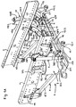
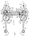
Nachstehend ist die erfindungsgemäße Lösung anhand eines in der Zeichnung dargestellten Ausführungsbeispiels näher erläutert. In der Zeichnung ist dieses Ausführungsbeispiel der erfindungsgemäßen Vorderachse in Fig. 1 A und 1 B in Perspektivansicht von schräg oben mit und ohne Rahmen-Längsträger, in Fig. 2 in Vorderansicht, in Fig. 3 in Seitenansicht und in Fig. 4 in Draufsicht gezeigt, wobei dort die Rahmen-Längsträger nur schwach-liniert angedeutet sind.The solution according to the invention is shown below with the aid of one shown in the drawing Embodiment explained in more detail. In the drawing, this embodiment is the Front axle according to the invention in Fig. 1 A and 1 B in a perspective view obliquely from above with and without frame side members, in Fig. 2 in front view, in Fig. 3 in side view and shown in plan view in Fig. 4, where the frame side members are indicated only weakly lined are.
Die Erfindung bezieht sich auf das Fahrgestell eines Nutzfahrzeugs, insbesondere Lastkraftwagen
oder eines solchen Fahrzeugs, das auf einem Lastkraftwagen-Fahrgestell basierend
für spezielle Anwendungszwecke entsprechend aufgebaut wird. In der Zeichnung sind als
Teile des Fahrgestells die beiden Längsträger des Rahmens mit 1 und 2 und die erfindungsgemäße
Vorderachse mit 3 bezeichnet. Diese Vorderachse 3 besteht aus einem Starrachskörper
4 und zwei Multifunktions-Längslenkern 5, 6 und ist über zwei je Achsseite eine Luftfeder
7, 8 und einen hierzu benachbarten Stoßdämpfer 9, 10 gegenüber den Rahmen abgestützt.
Zur Querführung der Vorderachse 3 ist ein Panhardstab 11 und zur Wankstabilisierung
des rahmenfesten Aufbaus gegenüber der Vorderachse 3 ist ein Stabilisator 12 vorgesehen.
Oberhalb des Starrachskörpers 4 ist außerdem ein spezieller, von vorne gesehen
etwa U-förmiger Querträger 13 vorgesehen, der mit den beiden Längsträgern 1, 2 des Rahmens
fest verbunden ist. Erfindungsgemäß kennzeichnet sich diese Vorderachse 3 des
weiteren durch folgende Merkmale:
Jeder der beiden Multifunktions-Längslenker 5, 6 weist drei funktionale Abschnitte 5/1, 5/2,
5/3 bzw. 6/1, 6/2, 6/3 auf, nämlich
Dabei ist jeder der beiden Multifunktions-Längslenker 5, 6 oben am Starrachskörper 4 aufliegend
vorzugsweise mittels mehrerer Schraubverbindungen kraftschlüssig befestigt. Es kann
zusätzlich zu diesem Kraftschluss auch noch ein Formschluss zwischen der Unterseite am
ersten Abschnitt 5/1, 6/1 jedes Multifunktions-Längslenkers 5, 6 und der Oberseite bzw. dem
oberen Bereich am Starrachskörper 4 vorgesehen sein, um einen absolut sicheren festen
Verbund dieser drei Bauteile 4, 5, 6 zu gewährleisten.Each of the two multi-function trailing
Des weiteren ragen die beiden Multifunktions-Längslenker 5, 6 mit ihren ersten Abschnitten
5/1, 6/2 geringfügig über den Starrachskörper 4 hinaus und weisen an ihren dort gegebenen
freien Enden jeweils eine integral angeformte oder angebaute Lagerstelle 5/4, 6/4 für
die Befestigung des unteren Endes des Stoßdämpfers 9, 10 und daneben eine Anschlussstelle
5/5, 6/5 für die Befestigung eines Lagerbügels 20, 21 auf, der mit einem eingebauten
Lager den Querschenkel 12/3 des U-förmigen Stabilisators 12 umfasst.Furthermore, the two multi-function trailing
Der an einem Multifunktions-Längslenker 5, 6 sich vom ersten Abschnitt 5/1, 6/1 ausgehend
nach unten zum plattenförmigen Abstützbereich 5/2, 6/2 hin erstreckende Übergangsbereich
weist außenseitig eine Einbuchtung 5/6 bzw. 6/6 auf, in die die zugehörige Luftfeder 7 bzw. 8
raumsparend eingreift, ohne aber deren Wand zu berühren.The one on a multi-function trailing
Jede Luftfeder 7, 8 weist einen Kolben 7%1, 8/1, oben eine Kopfplatte 7/2, 8/2 mit exzentrisch
darauf befestigter, insbesondere angeschweißter Anschlusskonsole 7/3, 8/3 und einen sich
zwischen Kopfplatte und Kolben erstreckenden Luftfederbalg 7/4, 8/4 auf. Jede Luftfeder 7, 8
ist mit ihrem Kolben 7/1, 8/1 an einem Zapfen 5/21, 6/21 am Abstützbereich 5/2, 6/2 des zugehörigen
Multifunktions-Längslenkers 5, 6 abgestützt befestigt und oben mit ihrer Kopfplatte
7/2, 8/2 unten am zugehörigen Rahmen-Längsträger 1, 2 anliegend abgestützt sowie mittels
der außen am betreffenden Rahmen-Längsträger 1, 2 angeflanschten Anschlusskonsole
7/3, 8/3 in dieser Anbaulage gehalten.Each
Jener Multifunktions-Längslenker 5 bzw. 6, der das achsseitige Anlenkorgan für den Panhardstab
11 bildet, weist einen nach oben und seitlich außen abragenden, integral angeformten
oder angebauten Lagerbock 22 auf, zwischen dessen beiden Seitenwangen der
Panhardstab 11 mit seinem achsseitigen Lagerauge 11/1 aufgenommen und gelagert ist.That multi-function trailing
Der U-förmige Querträger 13 ist im dargestellten Beispiel im Hinblick auf seine Brücken-Lagerfunktion
aus mehreren vorgefertigten und anschließend zusammengeschweißten Einzelteilen,
bei denen es sich vorzugsweise um Stahlblech-Stanz-/Biege-/Pressteile handelt,
zusammengesetzt, nämlich
Der Starrachskörper 4 weist die an sich bekannte Form einer Faustachse mit hochgekröpften
Enden auf, in deren vertikalen oder leicht schräg stehenden Durchgangsbohrungen über
Achsschenkelbolzen und zugehörige Lager die Achsträger der Räder schwenkbar anschließbar
sind.The
Der Starrachskörper 4 ist in sich weitestgehend biege- und torsionssteif ausgelegt. Vorzugsweise
handelt es sich bei dem Starrachskörper 4 um einen solchen, der unverändert auch für
andere Achsen verwendet werden kann. Außerdem sind die beiden Multifunktions-Längslenker
5, 6 im Bereich ihrer ersten Abschnitte 5/1, 6/1 und ihrer sich daran über besagte
Übergangsbereiche anschließenden abgekröpften Abstützbereiche 5/2, 6/2 im wesentlichen
biege- und torsionssteif ausgelegt. Die sich an letztere anschließenden Führungsarme
5/3, 6/3 dagegen sind nur in Vertikalrichtung gesehen vergleichsweise biegesteif, aber
um ihre Längsachse begrenzt tordierbar ausgebildet und hinsichtlich ihrer Biegesteifigkeit
sowie Torsionsfähigkeit auf den Gesamtstabilisierungseffekt in Verbindung mit dem Stabilisator
12 abgestimmt durch entsprechende Bemessung und Formgebung der hierfür maßgeblichen
Querschnitte.The
Claims (10)
Applications Claiming Priority (2)
| Application Number | Priority Date | Filing Date | Title |
|---|---|---|---|
| AT2332003 | 2003-02-17 | ||
| AT0023303A AT412549B (en) | 2003-02-17 | 2003-02-17 | CHASSIS OF A COMMERCIAL VEHICLE, ESPECIALLY TRUCKS |
Publications (3)
| Publication Number | Publication Date |
|---|---|
| EP1447247A2 true EP1447247A2 (en) | 2004-08-18 |
| EP1447247A3 EP1447247A3 (en) | 2006-05-24 |
| EP1447247B1 EP1447247B1 (en) | 2011-04-13 |
Family
ID=32660438
Family Applications (1)
| Application Number | Title | Priority Date | Filing Date |
|---|---|---|---|
| EP04002500A Expired - Lifetime EP1447247B1 (en) | 2003-02-17 | 2004-02-05 | Rigid axle suspension for a vehicle |
Country Status (3)
| Country | Link |
|---|---|
| EP (1) | EP1447247B1 (en) |
| AT (2) | AT412549B (en) |
| DE (1) | DE502004012391D1 (en) |
Cited By (3)
| Publication number | Priority date | Publication date | Assignee | Title |
|---|---|---|---|---|
| EP2382103A1 (en) * | 2008-12-29 | 2011-11-02 | Volvo Lastvagnar AB | Stabilizer arrangement of an axle and stabilizer |
| CN104401200A (en) * | 2014-10-31 | 2015-03-11 | 北京新能源汽车股份有限公司 | Hanging device |
| CN109050187A (en) * | 2018-10-12 | 2018-12-21 | 核心驱动科技(金华)有限公司 | Commercial vehicle, independent suspension structure and suspension support arms |
Citations (2)
| Publication number | Priority date | Publication date | Assignee | Title |
|---|---|---|---|---|
| DE19624242A1 (en) | 1996-06-18 | 1997-09-18 | Daimler Benz Ag | Vehicle front wheel suspension with rigid axle |
| EP0940325B1 (en) | 1998-03-04 | 2002-11-20 | MAN Nutzfahrzeuge Aktiengesellschaft | Chassis for a heavy-duty utility vehicle |
Family Cites Families (1)
| Publication number | Priority date | Publication date | Assignee | Title |
|---|---|---|---|---|
| FR2827814B1 (en) * | 2001-07-27 | 2005-12-02 | Renault Vehicules Ind | PNEUMATIC FRONT SUSPENSION ASSEMBLY FOR INDUSTRIAL VEHICLE |
-
2003
- 2003-02-17 AT AT0023303A patent/AT412549B/en not_active IP Right Cessation
-
2004
- 2004-02-05 DE DE502004012391T patent/DE502004012391D1/en not_active Expired - Lifetime
- 2004-02-05 AT AT04002500T patent/ATE505348T1/en active
- 2004-02-05 EP EP04002500A patent/EP1447247B1/en not_active Expired - Lifetime
Patent Citations (2)
| Publication number | Priority date | Publication date | Assignee | Title |
|---|---|---|---|---|
| DE19624242A1 (en) | 1996-06-18 | 1997-09-18 | Daimler Benz Ag | Vehicle front wheel suspension with rigid axle |
| EP0940325B1 (en) | 1998-03-04 | 2002-11-20 | MAN Nutzfahrzeuge Aktiengesellschaft | Chassis for a heavy-duty utility vehicle |
Cited By (5)
| Publication number | Priority date | Publication date | Assignee | Title |
|---|---|---|---|---|
| EP2382103A1 (en) * | 2008-12-29 | 2011-11-02 | Volvo Lastvagnar AB | Stabilizer arrangement of an axle and stabilizer |
| EP2382103A4 (en) * | 2008-12-29 | 2012-05-30 | Volvo Lastvagnar Ab | Stabilizer arrangement of an axle and stabilizer |
| CN104401200A (en) * | 2014-10-31 | 2015-03-11 | 北京新能源汽车股份有限公司 | Hanging device |
| CN109050187A (en) * | 2018-10-12 | 2018-12-21 | 核心驱动科技(金华)有限公司 | Commercial vehicle, independent suspension structure and suspension support arms |
| CN109050187B (en) * | 2018-10-12 | 2023-10-20 | 浙江盘毂动力科技有限公司 | Commercial vehicle, independent suspension structure and suspension support arm |
Also Published As
| Publication number | Publication date |
|---|---|
| ATE505348T1 (en) | 2011-04-15 |
| EP1447247A3 (en) | 2006-05-24 |
| AT412549B (en) | 2005-04-25 |
| DE502004012391D1 (en) | 2011-05-26 |
| ATA2332003A (en) | 2004-09-15 |
| EP1447247B1 (en) | 2011-04-13 |
Similar Documents
| Publication | Publication Date | Title |
|---|---|---|
| DE19809209A1 (en) | Chassis of a front-steering truck | |
| WO2008138451A1 (en) | Rear axle for a motor vehicle | |
| DE19605283B4 (en) | Trailing arm suspension for vehicles | |
| EP0798198A1 (en) | Front bearing for tilt cab truck | |
| EP1231129B1 (en) | Truck | |
| EP0806310A2 (en) | Independent suspension for a steered air suspended wheel of a bus or lorry | |
| EP0352541A1 (en) | Resilient axle suspension for motor vehicles, in particular for utility vehicles | |
| DE10055859B4 (en) | Axle construction for non-driven vehicle axles | |
| DE19809281A1 (en) | Chassis of a heavy commercial vehicle | |
| EP0940319B1 (en) | Chassis of a heavy utility vehicle | |
| DE4107303A1 (en) | AIR-SUSPENSED, STEERABLE WHEEL-SUPPORTING AXLE OF A MOTOR VEHICLE, IN PARTICULAR LOW-FLOOR BUS | |
| AT412549B (en) | CHASSIS OF A COMMERCIAL VEHICLE, ESPECIALLY TRUCKS | |
| AT504976B1 (en) | SPRING TRAP | |
| AT501922B1 (en) | COMMERCIAL VEHICLE, IN PARTICULAR LORRAINE, WITH SPECIAL SUSPENSION AND STEERING OF TWO ADJOINABLE FRONT AXLES | |
| EP0940322B1 (en) | Chassis for a heavy-duty utility vehicle | |
| EP0502311B1 (en) | Axle with steered wheels and pneumatic suspension for a motor vehicle | |
| EP0940325A1 (en) | Chassis for a heavy-duty utility vehicle | |
| EP0940323B1 (en) | Chassis for a heavy-duty utility vehicle | |
| AT413971B (en) | SPRING SUSPENSION OF A STARRACHSE ON THE CHASSIS FRAME OF A VEHICLE, IN PARTICULAR LORRY OR OMNIBUSSES | |
| EP0940321B1 (en) | Chassis for a heavy-duty utility vehicle | |
| DE4107305C2 (en) | Air-suspended, steerable wheel-bearing axle of a motor vehicle | |
| EP0940324A1 (en) | Chassis for a heavy-duty utility vehicle | |
| AT405500B (en) | Pneumatically or hydropneumatically sprung rigid axle of a truck or bus | |
| DE102006023783A1 (en) | Axle load compensating suspension for two adjacent rigid axles of commercial vehicle, comprises leaf springs stationary and movable suspended in specific arrangement | |
| AT407860B (en) | Suspension of an in particular air-suspended rear axle of a lorry or bus |
Legal Events
| Date | Code | Title | Description |
|---|---|---|---|
| PUAI | Public reference made under article 153(3) epc to a published international application that has entered the european phase |
Free format text: ORIGINAL CODE: 0009012 |
|
| AK | Designated contracting states |
Kind code of ref document: A2 Designated state(s): AT BE BG CH CY CZ DE DK EE ES FI FR GB GR HU IE IT LI LU MC NL PT RO SE SI SK TR |
|
| AX | Request for extension of the european patent |
Extension state: AL LT LV MK |
|
| RAP1 | Party data changed (applicant data changed or rights of an application transferred) |
Owner name: MAN NUTZFAHRZEUGE OESTERREICH AG |
|
| PUAL | Search report despatched |
Free format text: ORIGINAL CODE: 0009013 |
|
| AK | Designated contracting states |
Kind code of ref document: A3 Designated state(s): AT BE BG CH CY CZ DE DK EE ES FI FR GB GR HU IE IT LI LU MC NL PT RO SE SI SK TR |
|
| AX | Request for extension of the european patent |
Extension state: AL LT LV MK |
|
| 17P | Request for examination filed |
Effective date: 20060701 |
|
| AKX | Designation fees paid |
Designated state(s): AT DE FR IT NL SE |
|
| 17Q | First examination report despatched |
Effective date: 20080318 |
|
| GRAP | Despatch of communication of intention to grant a patent |
Free format text: ORIGINAL CODE: EPIDOSNIGR1 |
|
| GRAS | Grant fee paid |
Free format text: ORIGINAL CODE: EPIDOSNIGR3 |
|
| GRAA | (expected) grant |
Free format text: ORIGINAL CODE: 0009210 |
|
| AK | Designated contracting states |
Kind code of ref document: B1 Designated state(s): AT DE FR IT NL SE |
|
| REF | Corresponds to: |
Ref document number: 502004012391 Country of ref document: DE Date of ref document: 20110526 Kind code of ref document: P |
|
| REG | Reference to a national code |
Ref country code: DE Ref legal event code: R096 Ref document number: 502004012391 Country of ref document: DE Effective date: 20110526 |
|
| REG | Reference to a national code |
Ref country code: SE Ref legal event code: TRGR |
|
| REG | Reference to a national code |
Ref country code: NL Ref legal event code: T3 |
|
| PLBE | No opposition filed within time limit |
Free format text: ORIGINAL CODE: 0009261 |
|
| STAA | Information on the status of an ep patent application or granted ep patent |
Free format text: STATUS: NO OPPOSITION FILED WITHIN TIME LIMIT |
|
| RAP2 | Party data changed (patent owner data changed or rights of a patent transferred) |
Owner name: MAN TRUCK & BUS OESTERREICH AG |
|
| REG | Reference to a national code |
Ref country code: NL Ref legal event code: TD Effective date: 20120223 |
|
| REG | Reference to a national code |
Ref country code: DE Ref legal event code: R081 Ref document number: 502004012391 Country of ref document: DE Owner name: MAN TRUCK & BUS OESTERREICH AG, AT Free format text: FORMER OWNER: MAN NUTZFAHRZEUGE OESTERREICH AG, STEYR, AT Effective date: 20120125 Ref country code: DE Ref legal event code: R081 Ref document number: 502004012391 Country of ref document: DE Owner name: MAN TRUCK & BUS OESTERREICH AG, AT Free format text: FORMER OWNER: MAN STEYR AG, STEYR, AT Effective date: 20110317 |
|
| 26N | No opposition filed |
Effective date: 20120116 |
|
| REG | Reference to a national code |
Ref country code: DE Ref legal event code: R097 Ref document number: 502004012391 Country of ref document: DE Effective date: 20120116 |
|
| REG | Reference to a national code |
Ref country code: AT Ref legal event code: HC Ref document number: 505348 Country of ref document: AT Kind code of ref document: T Owner name: MAN TRUCK & BUS OESTERREICH AG, AT Effective date: 20120530 |
|
| REG | Reference to a national code |
Ref country code: FR Ref legal event code: PLFP Year of fee payment: 13 |
|
| REG | Reference to a national code |
Ref country code: FR Ref legal event code: PLFP Year of fee payment: 14 |
|
| REG | Reference to a national code |
Ref country code: FR Ref legal event code: PLFP Year of fee payment: 15 |
|
| REG | Reference to a national code |
Ref country code: DE Ref legal event code: R081 Ref document number: 502004012391 Country of ref document: DE Owner name: MAN TRUCK & BUS SE, DE Free format text: FORMER OWNER: MAN TRUCK & BUS OESTERREICH AG, STEYR, AT |
|
| REG | Reference to a national code |
Ref country code: AT Ref legal event code: PC Ref document number: 505348 Country of ref document: AT Kind code of ref document: T Owner name: MAN TRUCK & BUS SE, DE Effective date: 20211123 |
|
| PGFP | Annual fee paid to national office [announced via postgrant information from national office to epo] |
Ref country code: NL Payment date: 20230222 Year of fee payment: 20 |
|
| PGFP | Annual fee paid to national office [announced via postgrant information from national office to epo] |
Ref country code: FR Payment date: 20230223 Year of fee payment: 20 Ref country code: AT Payment date: 20230215 Year of fee payment: 20 |
|
| PGFP | Annual fee paid to national office [announced via postgrant information from national office to epo] |
Ref country code: SE Payment date: 20230222 Year of fee payment: 20 Ref country code: IT Payment date: 20230220 Year of fee payment: 20 Ref country code: DE Payment date: 20230227 Year of fee payment: 20 |
|
| REG | Reference to a national code |
Ref country code: NL Ref legal event code: PD Owner name: MAN TRUCK & BUS OESTERREICH GESMBH; AT Free format text: DETAILS ASSIGNMENT: CHANGE OF OWNER(S), ASSIGNMENT; FORMER OWNER NAME: MAN TRUCK & BUS OESTERREICH GESMBH Effective date: 20231031 |
|
| REG | Reference to a national code |
Ref country code: DE Ref legal event code: R071 Ref document number: 502004012391 Country of ref document: DE |
|
| REG | Reference to a national code |
Ref country code: NL Ref legal event code: MK Effective date: 20240204 |
|
| REG | Reference to a national code |
Ref country code: AT Ref legal event code: MK07 Ref document number: 505348 Country of ref document: AT Kind code of ref document: T Effective date: 20240205 |