EP1446201B1 - Appareil pour exercice physique - Google Patents
Appareil pour exercice physique Download PDFInfo
- Publication number
- EP1446201B1 EP1446201B1 EP02799189A EP02799189A EP1446201B1 EP 1446201 B1 EP1446201 B1 EP 1446201B1 EP 02799189 A EP02799189 A EP 02799189A EP 02799189 A EP02799189 A EP 02799189A EP 1446201 B1 EP1446201 B1 EP 1446201B1
- Authority
- EP
- European Patent Office
- Prior art keywords
- cable
- pulley
- exercise apparatus
- pulley wheel
- cylinder
- Prior art date
- Legal status (The legal status is an assumption and is not a legal conclusion. Google has not performed a legal analysis and makes no representation as to the accuracy of the status listed.)
- Expired - Lifetime
Links
Images


Classifications
-
- A—HUMAN NECESSITIES
- A63—SPORTS; GAMES; AMUSEMENTS
- A63B—APPARATUS FOR PHYSICAL TRAINING, GYMNASTICS, SWIMMING, CLIMBING, OR FENCING; BALL GAMES; TRAINING EQUIPMENT
- A63B21/00—Exercising apparatus for developing or strengthening the muscles or joints of the body by working against a counterforce, with or without measuring devices
- A63B21/15—Arrangements for force transmissions
- A63B21/151—Using flexible elements for reciprocating movements, e.g. ropes or chains
- A63B21/154—Using flexible elements for reciprocating movements, e.g. ropes or chains using special pulley-assemblies
- A63B21/155—Cam-shaped pulleys or other non-uniform pulleys, e.g. conical
-
- A—HUMAN NECESSITIES
- A63—SPORTS; GAMES; AMUSEMENTS
- A63B—APPARATUS FOR PHYSICAL TRAINING, GYMNASTICS, SWIMMING, CLIMBING, OR FENCING; BALL GAMES; TRAINING EQUIPMENT
- A63B21/00—Exercising apparatus for developing or strengthening the muscles or joints of the body by working against a counterforce, with or without measuring devices
- A63B21/00058—Mechanical means for varying the resistance
- A63B21/00069—Setting or adjusting the resistance level; Compensating for a preload prior to use, e.g. changing length of resistance or adjusting a valve
- A63B21/00072—Setting or adjusting the resistance level; Compensating for a preload prior to use, e.g. changing length of resistance or adjusting a valve by changing the length of a lever
-
- A—HUMAN NECESSITIES
- A63—SPORTS; GAMES; AMUSEMENTS
- A63B—APPARATUS FOR PHYSICAL TRAINING, GYMNASTICS, SWIMMING, CLIMBING, OR FENCING; BALL GAMES; TRAINING EQUIPMENT
- A63B21/00—Exercising apparatus for developing or strengthening the muscles or joints of the body by working against a counterforce, with or without measuring devices
- A63B21/008—Exercising apparatus for developing or strengthening the muscles or joints of the body by working against a counterforce, with or without measuring devices using hydraulic or pneumatic force-resisters
- A63B21/0085—Exercising apparatus for developing or strengthening the muscles or joints of the body by working against a counterforce, with or without measuring devices using hydraulic or pneumatic force-resisters using pneumatic force-resisters
- A63B21/0087—Exercising apparatus for developing or strengthening the muscles or joints of the body by working against a counterforce, with or without measuring devices using hydraulic or pneumatic force-resisters using pneumatic force-resisters of the piston-cylinder type
-
- A—HUMAN NECESSITIES
- A63—SPORTS; GAMES; AMUSEMENTS
- A63B—APPARATUS FOR PHYSICAL TRAINING, GYMNASTICS, SWIMMING, CLIMBING, OR FENCING; BALL GAMES; TRAINING EQUIPMENT
- A63B21/00—Exercising apparatus for developing or strengthening the muscles or joints of the body by working against a counterforce, with or without measuring devices
- A63B21/15—Arrangements for force transmissions
- A63B21/151—Using flexible elements for reciprocating movements, e.g. ropes or chains
- A63B21/154—Using flexible elements for reciprocating movements, e.g. ropes or chains using special pulley-assemblies
- A63B21/156—Using flexible elements for reciprocating movements, e.g. ropes or chains using special pulley-assemblies the position of the pulleys being variable, e.g. for different exercises
-
- A—HUMAN NECESSITIES
- A63—SPORTS; GAMES; AMUSEMENTS
- A63B—APPARATUS FOR PHYSICAL TRAINING, GYMNASTICS, SWIMMING, CLIMBING, OR FENCING; BALL GAMES; TRAINING EQUIPMENT
- A63B23/00—Exercising apparatus specially adapted for particular parts of the body
- A63B23/035—Exercising apparatus specially adapted for particular parts of the body for limbs, i.e. upper or lower limbs, e.g. simultaneously
- A63B23/03516—For both arms together or both legs together; Aspects related to the co-ordination between right and left side limbs of a user
- A63B23/03533—With separate means driven by each limb, i.e. performing different movements
- A63B23/03541—Moving independently from each other
-
- A—HUMAN NECESSITIES
- A63—SPORTS; GAMES; AMUSEMENTS
- A63B—APPARATUS FOR PHYSICAL TRAINING, GYMNASTICS, SWIMMING, CLIMBING, OR FENCING; BALL GAMES; TRAINING EQUIPMENT
- A63B23/00—Exercising apparatus specially adapted for particular parts of the body
- A63B23/035—Exercising apparatus specially adapted for particular parts of the body for limbs, i.e. upper or lower limbs, e.g. simultaneously
- A63B23/12—Exercising apparatus specially adapted for particular parts of the body for limbs, i.e. upper or lower limbs, e.g. simultaneously for upper limbs or related muscles, e.g. chest, upper back or shoulder muscles
- A63B23/1209—Involving a bending of elbow and shoulder joints simultaneously
-
- A—HUMAN NECESSITIES
- A63—SPORTS; GAMES; AMUSEMENTS
- A63B—APPARATUS FOR PHYSICAL TRAINING, GYMNASTICS, SWIMMING, CLIMBING, OR FENCING; BALL GAMES; TRAINING EQUIPMENT
- A63B21/00—Exercising apparatus for developing or strengthening the muscles or joints of the body by working against a counterforce, with or without measuring devices
- A63B21/40—Interfaces with the user related to strength training; Details thereof
- A63B21/4027—Specific exercise interfaces
- A63B21/4033—Handles, pedals, bars or platforms
- A63B21/4035—Handles, pedals, bars or platforms for operation by hand
-
- A—HUMAN NECESSITIES
- A63—SPORTS; GAMES; AMUSEMENTS
- A63B—APPARATUS FOR PHYSICAL TRAINING, GYMNASTICS, SWIMMING, CLIMBING, OR FENCING; BALL GAMES; TRAINING EQUIPMENT
- A63B21/00—Exercising apparatus for developing or strengthening the muscles or joints of the body by working against a counterforce, with or without measuring devices
- A63B21/40—Interfaces with the user related to strength training; Details thereof
- A63B21/4041—Interfaces with the user related to strength training; Details thereof characterised by the movements of the interface
- A63B21/4043—Free movement, i.e. the only restriction coming from the resistance
-
- A—HUMAN NECESSITIES
- A63—SPORTS; GAMES; AMUSEMENTS
- A63B—APPARATUS FOR PHYSICAL TRAINING, GYMNASTICS, SWIMMING, CLIMBING, OR FENCING; BALL GAMES; TRAINING EQUIPMENT
- A63B2225/00—Miscellaneous features of sport apparatus, devices or equipment
- A63B2225/09—Adjustable dimensions
-
- A—HUMAN NECESSITIES
- A63—SPORTS; GAMES; AMUSEMENTS
- A63B—APPARATUS FOR PHYSICAL TRAINING, GYMNASTICS, SWIMMING, CLIMBING, OR FENCING; BALL GAMES; TRAINING EQUIPMENT
- A63B2225/00—Miscellaneous features of sport apparatus, devices or equipment
- A63B2225/30—Maintenance
-
- A—HUMAN NECESSITIES
- A63—SPORTS; GAMES; AMUSEMENTS
- A63B—APPARATUS FOR PHYSICAL TRAINING, GYMNASTICS, SWIMMING, CLIMBING, OR FENCING; BALL GAMES; TRAINING EQUIPMENT
- A63B23/00—Exercising apparatus specially adapted for particular parts of the body
- A63B23/035—Exercising apparatus specially adapted for particular parts of the body for limbs, i.e. upper or lower limbs, e.g. simultaneously
- A63B23/03508—For a single arm or leg
-
- Y—GENERAL TAGGING OF NEW TECHNOLOGICAL DEVELOPMENTS; GENERAL TAGGING OF CROSS-SECTIONAL TECHNOLOGIES SPANNING OVER SEVERAL SECTIONS OF THE IPC; TECHNICAL SUBJECTS COVERED BY FORMER USPC CROSS-REFERENCE ART COLLECTIONS [XRACs] AND DIGESTS
- Y10—TECHNICAL SUBJECTS COVERED BY FORMER USPC
- Y10S—TECHNICAL SUBJECTS COVERED BY FORMER USPC CROSS-REFERENCE ART COLLECTIONS [XRACs] AND DIGESTS
- Y10S482/00—Exercise devices
- Y10S482/907—Stretching
Definitions
- the present invention relates to an exercise apparatus and, more particularly, to an adjustable exercise apparatus that can be used for a multitude of exercises.
- weight type in which weights provide resistance to the exertion of muscular force.
- Such machines commonly employ weight stacks that allow a user to vary the weight lifted during the exercise.
- U.S. Patent Nos. 6,447,430 , 5,776,040 , and 4,500,089 are examples of such machines.
- Weight stack machines often, in normal use, do not provide a consistent resistance.
- a weight lifter normally thinks that 100 pounds of weight will provide 100 pounds of resistance throughout the exercise stroke; however, this is true only if the weight is moved at a slow and generally constant speed. If the weight lifter quickly moves the weight, the changes in speed of movement will cause the weight to change. Accordingly, manufacturers of weight stack machines commonly instruct those training on their machines to train at a speed of out on two seconds and back on four seconds, thus keeping the speed slow enough to make the acceleration forces insignificant. However, if a user accelerates the weight during the exercise stroke, the resistance force will change.
- Pneumatic exercise equipment has been developed in response to this shortcoming of weight stacks. Such exercise equipment simulates the desired characteristics of a weight stack exercise machine by easily permitting the weight lifter to increase or decrease the resistance; however, pneumatic exercise equipment also permits the weight lifter to increase speed without the resistance changing because such machines do not have a significant inertia of motion. Consequently, pneumatic exercise equipment ensures full muscular effort throughout the stroke.
- Pneumatic exercise equipment commonly include a pneumatic cylinder with a piston rod that moves linearly.
- a piston divides the cylinder into two chambers.
- the rod is connected to the piston and extends through one of the chambers.
- the piston rod also is usually operatively connected to a handle or other user interface. As the user pushes (or pulls, depending upon which cylinder chamber is pressurized) on the handle, movement of the rod is resisted by air within the cylinder. This resistance to further movement provides exercise resistance.
- an air reservoir also known as an accumulator
- the air line allows air to flow between the cylinder and the accumulator and thus equalizes the air pressure between these components.
- the user can choose a preset resistance force by controlling the air pressure within the cylinder/accumulator assembly.
- a source of compressed air communicates with the accumulator through an air supply line.
- An air addition valve, a pressure gauge, and a bleed-off valve are interposed in the line.
- the pressure gauge preferably is configured to display the resistance force anticipated for the user rather than the actual air pressure within the system.
- the user adds or removes air from the pneumatic system. Air is added by actuating the air addition valve. Air is removed by actuating the bleed-off valve.
- U.S. Patent No. 4,257,593 discloses an example of a pneumatic exercise device.
- the resistance curve produced for a given air pressure as the piston rod is moves from an initial position to a fully retracted position (or fully extended position if pulled) remains substantially the same even though the speed at which the piston rod moves may vary.
- the resistance will increase during the exercise stroke as the air compresses under the exerted force of the user.
- US 6,142,919 A discloses a low profile physical exercising device having a handle to be grasped by an exercising person, an elongate frame having a plurality of attachment points disposed along the frame, a fixed pulley fixedly attached to the frame and a detachable pulley detachably connectable to any one of said attachment points and an elastic resistance member having one end attached to the frame and another end connected to a flexible wire.
- the elastic resistance member can be in the form of elastic straps made of rubber, known as "bung cords". Although not discussed in further detail the straps can be made as coil springs or compressed air cylinders. Also, the resistance element is discussed in a configuration as a weight as known in the art.
- the present exercise apparatus offers a range of adjustability and resistances so that a single piece of exercise equipment can be used to perform a multitude of different exercises.
- Another aspect of the exercise apparatus involves providing a pneumatic exercise apparatus that produces generally constant resistance throughout the entire exercise stroke.
- An additional aspect involves a compact pneumatic exercise apparatus that can be mounted to or supported by the floor, wall or other support structure.
- an exercise apparatus comprising a frame and a user interface (e.g., a handle) that is movable between a retracted position and an extended position.
- a pneumatic actuator is disposed on the frame and includes a cylinder and a piston rod. The piston rod extends from the cylinder along a stroke axis.
- a pulley wheel is rotatably connected to the piston rod at a location offset from a center of the pulley wheel and a cable is wrapped about at least a portion of the pulley wheel.
- the cable has a first cable end and a second cable end. The first cable end is fixed to the frame and the second cable end is coupled to the user interface.
- an exercise system comprising a station frame and a resistance unit being configured to provide an exercise resistance force.
- the resistance unit cooperates with a user interface and is movably connected to the station frame. In this manner, the resistance unit can be moved between at least a first position and a second position on the frame.
- the exercise system comprises at least two resistance units. At least one of the units is movably connected to the frame, and preferably, both are movably connected to the frame.
- an exercise apparatus comprising a pneumatic cylinder, a first air reservoir and at least a second air reservoir.
- the pneumatic cylinder and the reservoirs are connected by at least one air equalization line so as to maintain generally equal air pressures within the cylinder and the reservoirs.
- the second reservoir selectively communicates with the first reservoir and the cylinder.
- An additional aspect of the present invention involves a seat assembly that is movably connected to a frame of an exercise apparatus. In this manner the seat assembly can be moved between at least a first position and a second position.
- the seat assembly preferably includes a bottom that is connected to a support post.
- the support post has at least one wheel.
- the seat assembly can be connected to a guidepost of the frame, and preferably, the seat assembly can slide relative to the guidepost and be selectively fixed relative to the guidepost to vary its position and orientation.
- the present exercise apparatus can take a variety of forms and can be used in a variety of manners as will be apparent from the description of the following embodiments. Additionally, some of the embodiments include a combination of some of the aspects and features described above, and others will include additional aspects and features. As noted above, not all of the aspects and features of the present invention need to be employed in a single embodiment.
- Each illustrated embodiment includes a pneumatic resistance unit that allows for variable resistance and variable degrees and extensions of motion by the user.
- the resistance units are designed to permit the user to perform a wide variety of exercises to work various muscles or muscle groups with the same piece of equipment.
- the resistance unit can be stationary or movable, and can include movable pulleys that allow the user to change the direction in which the user pushes or pulls during a set of the exercise repetitions.
- Various aspects, features and advantages of the following apparatuses can be used with other types of resistance mechanisms (for example, but without limitation, weight stacks), as described below. Accordingly, the following will first describe the resistance unit as a stationary exercise apparatus and then will describe additional embodiments of the exercise apparatus that can employ the resistance unit. Like reference numbers will be used to indicate similar components among the illustrated preferred embodiments.
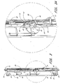
- the resistance unit 10 (i.e., power module) in this embodiment forms an exercise apparatus that can be mounted to a support structure, such as, for example, but without limitation, a wall, a frame or a post.
- the resistance unit 10 includes a user interface 12, which the user grips, an extension mechanism 14 that provides a range of movement to the user interface 12, a resistance assembly 16 that resists movements of the user interface 12, a coupling mechanism 18 that couples the resistance assembly 16 to the extension mechanism 14, and a housing 20.
- the housing 20 supports these components and preferably encloses the resistance assembly 16, the coupling mechanism 18, and at least a portion of the extension mechanism 14.
- the user interface 12 takes the form of a handle.
- the user interface can take other forms.
- the user interface can be a band (preferably of an adjustable size) that is sized to fit around a portion of the user's body, e.g., a waistband or an ankle band.
- the user interface additionally can be a bar, a foot pedal, or other lifting equipment.
- the user interface thus can be any article or mechanism that a user acts against or interacts with and that is attached, either directly or indirectly, to the extension mechanism 14.
- the user interface 12 preferably is moved between two positions during an exercise and can be moved from one extreme position to another extreme position.
- the handle 12 normally resides in a retracted position with a cable end to which the handle 12 is attached being fully retracted up to the unit 10.
- a user can move the handle 12 from the retracted position to an extended position in which the cable end of extension mechanism 14 is pulled to its farthest position from the housing 20.
- the exercise movement can involve movement between any two positions between (and possibly including) the retracted and extended positions in order to accommodate different exercises and different size weight lifters.
- the housing 20 is substantially rigid and is defined by a frame 22 and a cover assembly 24.
- the frame 22 of the illustrated embodiment includes a vertical guidepost or tract 26 that is disposed on a front side 28 of the housing 20.
- An upper cross member 30 and a lower cross member 32 are connected at the upper and lower ends of the guidepost 26 via upper and lower brackets 34, 36, respectively.
- a front cover 38 is disposed behind (but spaced apart from) the guidepost 26 and is attached to the upper and lower cross members 30, 32 and brackets 34, 36.
- a plurality of internal ribs and brackets are attached to the front cover 38 and to the upper and lower cross members 30, 32 to support various components of the extension mechanism 14, the coupling mechanism 18, and the resistance assembly 16 within the housing 20, as well as any electronic controls for the resistance unit 10.
- the ribs not only increase the rigidity of the housing 20, but also include holes through which a cable of the extension mechanism 14 passes in order to ensure that the cable maintains its position within the housing 20.
- a cylinder-mounting bar 40 depends from the upper cross member 30.
- the vertical guidepost 26 extends along a central plane that divides the unit 10 into first and second halves (right and left halves as viewed from the front). From the exterior, the halves preferably have symmetrical configurations. Inside, however, the cylinder-mounting bar 40 is disposed at a position slightly offset from the center plane (i.e., generally offset to one side of the vertical guidepost 26).
- the cover assembly 24 additionally includes a back cover 42.
- a side hinge 44 connects the back cover 42 to the front cover 38.
- the opposite side of the covers 38, 42 are connected together by removable fasteners or one or more latches. In this manner, the interior of the unit 10 can be readily opened for servicing or inspection.
- the vertical guidepost 26 preferably comprises a square steel tube and has a series of locking holes formed through a sidewall thereof.
- the guidepost 26, however, can have other configurations (e.g., an I-beam configuration).
- the guidepost 26 supports a cable guide mechanism 46 that includes a traveler 48.
- the traveler 48 is configured to slide over the guidepost 26.
- the traveler 48 has a corresponding tubular shape and is sized to slip over the guidepost 26. In this manner, the traveler 48 can be moved vertically over the guidepost 26.
- a knob 50 is fit onto the traveler 48.
- the knob controls a dowel (not shown) that selectively engages one of the locking holes formed in the front side of the guidepost 26. In this manner, the user can releasably select the vertical position of the traveler 48.
- the traveler 48 supports a handle pulley assembly 52 of the cable guide mechanism 46 via a hinge connection 54.
- the hinge connection 54 allows the handle pulley assembly 52 to rotate about a vertical axis.
- the handle pulley assembly 52 comprises a pair of pulleys 56, 58 that are arranged one above the other with the lower one 58 positioned slightly forward of the upper one 56. In the illustrated embodiment, the offset between the upper and lower pulleys 56, 58 is less than the diameter of either pulley.
- the pulleys 56, 58 preferably have the same diameter; however, pulleys of different size diameters can also be used.
- the pulley assembly 52 includes a plurality of holes, as best seen in Figure 3A , formed in its side brackets. The holes lighten the weight of the pulley assembly 52 in order to respond more quickly to the movement of the user and to do so with less resistance.
- a first end 60 of a cable 62 (a "user cable") of the extension mechanism 14 is threaded between the pulleys 56, 58 of the handle pulley assembly 52.
- the handle 12 is connected to this first end 60 of the user cable 62.
- the handle 12 preferably is releasably connected to the end of the user cable 62 in order to exchange different types of user interface.
- the arrangement of the hinge connection 54 and handle pulley assembly 52 automatically aligns the user cable 62 with the handle pulley assembly 52 when the handle 12 is pulled from substantially any direction outwardly from the unit 10.
- a second end 64 of the user cable 62 is connected to the traveler 48 and extends downwardly from the traveler 48 to a bottom pulley set 66 (see Figure 3 ).
- the bottom pulley set 66 directs the user cable 62 to the rear and inside of the unit housing 20.
- the user cable 62 extends upwardly in the housing 20 to a series of pulleys that, in the illustrated embodiment, collectively comprise a block-and-tackle mechanism 68 of the extension mechanism 14.
- the user cable 62 is wound through the pulley blocks and is then directed upwardly to an upper pulley set 70, which directs the user cable 62 to the front side 28 of the housing 20 and downward to the handle pulley assembly 52.
- the user cable 62 terminates at its first end 60, which, as noted above, is connected to the handle 12. Since the user cable 62 is threaded through the block-and-tackle mechanism 68 and back to the traveler 48, the handle pulley assembly 52 can be moved vertically along the guidepost 26 without loosening the user cable 26 or affecting the block-and-tackle mechanism 68, as described in more detail below
- the user cable 62 can be a formed of a synthetic material, such as a polymer.
- a polyester/nylon blend rope is a polyester/nylon blend rope; however, a coated steel cable can also be used.
- the user cable 62 can comprises 3.2 mm (1/8-inch) wire cable with a plastic sheathing, and most of the pulleys of the unit that support the cable can have a diameter of about 12.7 cm (five inches).
- any suitable cable and pulley size can be employed, it is preferable that the associated pulleys have a diameter about 40 times the diameter of the coated-wire cable. Smaller diameter pulleys, however, can be used with other types of cables, e.g., 8.9 cm (3.5-inch) diameter pulleys used with polyester/nylon blend rope.
- the block-and-tackle mechanism 68 includes an upper pulley block 72 and a lower pulley block 74.
- Each pulley block 72, 74 in the illustrated embodiment, includes two pulleys; however, each block 72, 74 can include fewer or more pulleys.
- the upper pulley block 72 is attached to upper cross member 30 or bracket 34 of the frame 22.
- the user cable 62 extends upward inside the housing 20 from the bottom pulley set 66 and wraps around one of the pulleys of the upper pulley block 72.
- the cable 62 then extends down and wraps around one of the pulleys of the lower pulley block 74, and then up and down again wrapping around the second pulleys of the upper and lower pulley blocks 72, 74, respectively.
- the user cable 62 extends upward to the upper pulley set 70, as described above. Accordingly, as the user pulls the user cable 62 from the unit 10 (i.e., pulls the cable 62 toward the extended position), the block-and-lackle shortens in the process as the lower pulley block 74 moves upward toward the upper pulley block 72.
- the lower pulley 74 remains generally stationary if the traveler 48 is moved without pulling on the handle 14. Both ends of the user cable 62 also move with the traveler 48. Accordingly, upward movement of the traveler 48 pulls up on the lower section of the user cable 62, which consequently pulls into the block-and-tackle mechanism 68 from the top any would-be slack in the upper section of the user cable 62.
- the lower pulley block 74 constitutes an output member of the block-and-tackle mechanism 68 in the illustrated embodiment.
- the load to be "lifted” is connected to lower pulley block 74 in the illustrated embodiment.
- the coupling mechanism 18 in the illustrated embodiment includes a main cable 76.
- a first end 78 of the main cable 76 is attached to the lower pulley block 74.
- the second end 80 of the main cable 76 is fixed to the housing 20.
- the main cable 76 cooperates with the resistance assembly 16 (see Figure 4A ).
- the user cable 62 winds through the pulley blocks 72, 74, lifting the lower pulley block 74 and correspondingly pulling on the main cable 76. Force from the resistance assembly 16 is communicated through the main cable 76 to the lower pulley block 74 and further to the user cable 62.
- the block-and-tackle mechanism 68 is arranged with four pulleys and four lengths of line between the pulleys.
- the resultant force at the handle 12 is one-fourth of the force supplied by the resistance assembly 16, and the stroke length of handle 12 is about four times the stroke length of the pulley block output (i.e., the distance of between upper and lower pulley blocks 72, 74 when the handle 12 is in the retracted position).
- any pulley assembly can be used to achieve any desired force reduction or stroke elongation.
- the resistance assembly 16 of the illustrated embodiment includes a pneumatic actuator 82.
- the pneumatic actuator 82 is a linear actuator that includes a cylinder 84 and a piston rod 86.
- the cylinder 84 includes a cylinder body and a piston that slides within the cylinder body.
- the piston divides the cylinder body into two variable volume chambers. At least one of the chambers only selectively communicates with the atmosphere so as to provide the desired resistance.
- the other chamber can be open to the atmosphere; however, in some applications, both chambers can be pressurized (e.g., be of equal pressure), can selectively communicate with the atmosphere and/or can communicate with each other. In the illustrated embodiment, however, one of the chambers communicates with the atmosphere (e.g., the air within the housing) so as not to resist movement of the piston.
- the piston rod 86 is connected to the piston and extends through one of the variable volume chambers.
- the piston rod 86 moves linearly along a stroke axis as the piston slides within the cylinder bore.
- the stroke length of the piston rod 86 is sufficient to provide the desired stroke for the block-and-tackle mechanism 68 (as discussed above).
- a cap closes the opposite end of the cylinder body (i.e., opposite of the end through which the piston rod extends).
- the cap includes a lug.
- a pivot pin 88 preferably secures the lug to the cylinder-mounting bar 40 such that the pneumatic actuator 82 can pivot within the housing 20 about the pivot pin 88.
- the pneumatic actuator 82 in the illustrated embodiment hangs from the bar 40 within the housing 20 so as to pivot within a plane that is generally parallel to the front side 28 of the housing 20; however, in some applications, the cylinder body can be rigidly fixed within the housing 20.
- the actuator 82 in this position thus has an upper chamber and a lower chamber. In the illustrated embodiment, the lower chamber is open to the atmosphere (preferably through a filter) and the upper chamber is pressurized.
- At least several components of the pneumatic cylinder are preferably formed of a polymer (e.g., plastic) in order to lighten the weight of the resistance unit 10 and to decrease production costs.
- Such components can include the cylinder body, the piston and one or more of the end caps of the cylinder.
- the upper chamber preferably communicates with at least one accumulator 90, as seen in Figure 4 .
- the accumulator 90 is preferably rigidly mounted within the housing 20 at a location next to the cylinder 84.
- the accumulator 90 is mounted on one side of the cylinder 84 and the block-and-tackle mechanism 68 is disposed on the other side of the cylinder 84 within the housing 20.
- An air equalization line 92 connects the accumulator with the cylinder 84 so as to expand effectively the variable volume of the upper chamber. In this manner, the effective air volume of the cylinder is increased, and air pressure thus will not increase as dramatically when the piston is moved.
- the accumulator 90 and the upper chamber also selectively communicate with a source of pressurized air and with the atmosphere.
- an air compressor which can be remotely disposed relative to the exercise apparatus, communicates with the upper chamber through an inlet valve.
- a button 94 that actuates the inlet valve preferably is accessible from the front side 28 of the housing 20 (as seen in Figure 1 ) and is marked with appropriate indicia (e.g., "+"). Pushing the button 94 adds air pressure to the charged side of the cylinder 84, e.g., the upper chamber in the illustrated embodiment.
- An outlet valve communicates with the charged side of the cylinder to selectively expel air to the atmosphere in order to decrease air pressure on the charged side of the cylinder 84.
- a button 96 that actuates the outlet valve also is preferably accessible from the front side 28 of housing 20 and is marked with appropriate indicia (e.g., "-"). A user thus can adjust, i.e., increase or decrease, the air pressure within the resistance assembly 16 by operating the appropriate valves.
- the coupling mechanism 18 transfers a resistant force from the resistance assembly 16 to the extension mechanism 14 to oppose movement of the handle 12 by the user.
- the coupling mechanism 18 includes the main cable 76 that is pivotally fixed at its first end 78 to the lower pulley block 74 and is rigidly fixed at its second end 80 to the housing 20.
- the main cable 76 in the illustrated embodiment, includes a ball swaged onto the first end 78.
- the ball fits through a keyway slot formed in the lower pulley block 74 and nests in a receptacle (not shown).
- the receptacle/ball connection secures the first end 78 of the main cable 76 to the lower pulley block 74, yet allows the cable 76 to pivot relative to the pulley block 74.
- the coupling mechanism 18 also includes a main pulley or pulley wheel 98 that preferably is circular and has a larger diameter than the pulleys of the block-and-tackle mechanism 68.
- the main pulley 98 is rotatably attached to the end of the piston rod 86 to permit rotation of the main pulley 98 relative to the piston rod 86.
- the main pulley 98 includes a bearing 100 to which a bolt or pivot shaft couples to the piston rod end.
- a cable channel is disposed about the periphery of the main pulley 98, and the main cable 76 fits therein.
- a cable lock notch 102 is disposed along the peripheral edge of the main pulley 98.
- the cable lock notch 102 is disposed at the point that will provide a sufficient amount of the main cable 76 to unwind from the main pulley 76 to accommodate the stroke length of the piston rod 86.
- a cable lock member 104 is disposed about the main cable 76, and fits into the cable lock notch 102. In this manner, the position of the main cable 76 relative to the main pulley 98 is maintained.
- a guide preferably is provided next to the pulley wheel and is arranged such that the pulley wheel rides along the guide.
- the guide is an elongate cable support member 106 that extends inwardly from a first side of the housing 20, which is farthest from the extension mechanism (e.g., the left side, as viewed from the front, in the illustrated embodiment).
- the guide need not in all applications support the cable 76 or hold the cable 76 within the peripheral channel of the main pulley 98.
- the cable support member 106 is positioned immediately adjacent the downwardly extending portion of the main cable 76 adjacent the first side of the housing 20.
- the cable support member 106 preferably has a thickness that is about equal to the diameter of the cable 76, and is thin enough to fit at least partially within the peripheral channel of the main pulley 98. As the main pulley 98 is drawn upwardly, it rolls on the cable 76 and the support member 106. The support member 106 thus prevents any substantial "play" in the coupling mechanism 18 that would otherwise occur and, in fact, helps hold the main pulley 98 securely in place during operation of the device. Since the cable 76 generally does not slide relative to the cable support member 106, wear of the cable 76 and the pulley 98 is substantially lessened.
- a cable cover 108 preferably extends from a second side of the housing 20 (e.g., the right side, as viewed from the front, in the illustrated embodiment).
- the cable cover 108 shields the main cable 76.
- the peripheral edge of the main pulley 98 preferably fits within the cover 108 so that the cover 108 can help keep the main pulley 98 properly aligned.
- the cable cover 108 does not contact or support the main pulley 98 or the main cable 76.
- a first section of the main cable 76 extends from the main pulley 98 toward the first cable end 78 and a second section of the main cable 76 extends from the main pulley 98 toward the second cable end 80.
- each of the first and second cable sections has a generally vertical orientation.
- the pneumatic actuator 82 is arranged such that its stroke axis lies generally parallel to the first section of the main cable 76 at least initially when the handle 12 is in its retracted position.
- the above configuration of the extension mechanism 14, the resistance assembly 16 and the coupling mechanism 18 provides for a compact resistance unit 10.
- the resistance unit 10 can be readily used in a variety of applications, as made clear from the additional embodiments. It is also lightweight and involves relative few components, yet provides a full range of movement, versatility in the types of exercises that can be performed, and variability in the amount of resistance provided.
- the resistance force will increase somewhat, although not as dramatic as it would without the accumulator.
- the resistance force be maintained at a generally constant level throughout the exercise stroke (e.g., the cable tension remains generally constant).
- the illustrated embodiment comprises a mechanism for controlling the resistance force over the stroke of the piston rod 86; however, the resistance unit 10 need not include such a mechanism in all applications.
- the bearing 100 is offset from the center of the main pulley 98.
- the offset position causes the block-and-tackle mechanism 68 to gain additional leverage over the cylinder as the main pulley 98 rotates.
- the main pulley 98 rotates, thereby moving the bearing 100 away from the side of the main cable 76 that is connected to the block-and-tackle mechanism 68.
- the main pulley 98 thus acts as a simple beam with a movable fulcrum.
- the offset position causes the pneumatic actuator 82 to pivot and produce a force vector that is skewed relative to the direction in which the main pulley 98 is being drawn. Accordingly, only a portion of the resistance force opposes the movement of the main pulley 98 toward the cylinder 84; the other force component forces the main pulley 98 toward a side of the housing 20. Consequently, the overall effective resistance force remains generally constant throughout the entire stroke of the piston rod 86.
- the cylinder 84 is generally vertically oriented when the stroke begins, but pivots toward the first side of the housing as the stroke progresses.
- the bearing 100 is located such that a line L that passes through the center of the main pulley 98 and the bearing 100 lies generally normal to the stroke axis of the piston rod 86.
- the line L extends horizontally.
- the position of the cylinder 84 at the start and throughout the stroke can be varied. The cylinder, however, preferably does not cause the main pulley 98 to pull away from the cable support member 106.
- a similar effect can be achieved by changing the profile of the guide (e.g., the cable support member 106) or the shape of the main pulley 98 such that the pneumatic actuator 82 pivots as main pulley 98 moves toward the cylinder 84.
- the block-and-tackle mechanism 68 gains leverage and that only a portion of the resistance force opposes the movement. It also is understood that this effect can be achieved with gears and like mechanism in the place of the main pulley and main cable.
- these techniques can also be used either alone or together to produce resistance force curves that increase and decrease throughout the exercise stroke.
- the resistance force desirably increase toward the middle of the stroke and then decreases at the end.
- the initial orientation of the pneumatic actuator, the degree of offset of the bearing (if any), the initial position of the bearing, the shape of the main pulley, and/or the profile of the guide can be used to produce the desired force curve.
- the cable support member 106 preferably extends in a direction that is generally parallel to a plane that is perpendicular to the face of the main pulley 98 and that passes through a center point of the main pulley 98.
- the cable support member 106 is disposed on one side of the plane and the point of attachment (e.g., the pivot pin 88) of the pneumatic actuator 82 to the frame 22 is located on the other side of the plane.
- the bearing 100 is on the same side of the plane as the point of attachment of the pneumatic cylinder 82 to the frame 22 at least when the handle 12 is in its retracted position.
- the stroke axis of the piston rod 86 extends in a direction generally parallel to the plane.
- the stroke of the pneumatic cylinder piston rod 86 is about 30.5 cm (12 inches), and the main pulley 98 has a diameter of about 20.3 cm (8 inches). Over the full stroke of the piston 86, about 30.5 cm (12 inches) of cable 76 unwinds from the main pulley 98.
- the lower pulley block 74 moves about 6.1 cm (24 inches), or about 2 feet. Since the block-and-tackle mechanism 68 is configured to increase the stroke length by 4 times, a total cable stroke at the handle 12 is about 2.44 m (8 feet). In this manner, a compact, light and reliable resistance unit 10 provides 2.44 m (8 feet) of cable travel.
- the main pulley 98 is substantially circular, has a diameter of about 8 inches, and the bearing/connection point of the main pulley is disposed 7/8 of an inch off-center.
- this configuration of the main pulley 98 combined with the illustrated configuration of the pneumatic resistance assembly 16, provides a generally constant exercise force (e.g., ⁇ 10%) throughout the piston rod stroke. It is to be understood that the above dimensions apply only to the illustrated embodiment, are by way of example only and are not intended to limit the invention, and the principles discussed above can be employed to create any type of exercise apparatus having any desired stroke length and resistance curves.
- connection bearing can be varied and/or an ellipsoid, irregular or other non-circular main pulley shape can be employed.
- main pulley rotated through a range of angles from about 0° to about 174°.
- Variable resistance forces can also be achieved by beginning rotation at a different angle such as, for example, 5°, - 5°, 90°, etc., relative to the horizontal.
- the operation of the illustrated resistance unit will be described in connection with Figures 4A , 4B and 4C .
- the generally horizontal line L intersects the bearing 100 and the center of the main pulley 98.
- This position of the main pulley 98 is considered to be 0° relative to horizontal.
- the piston rod 86 is preferably substantially vertically oriented in this unloaded position.
- the bearing 100 rotates from about 0° through about 170° during the stroke of the piston rod 86.
- the offset connection of the piston rod 86 to the main pulley 98 causes the pneumatic cylinder to pivot about the pivot point 88 when the main pulley rotates 98.
- the cylinder 84 is directed at least partially toward a first side of the housing 20.
- the pneumatic actuator 82 exerts a substantial force during compression of the cylinder.
- the vertical component of the force is translated along the longitudinal length of the main cable 76.
- the horizontal component of the force tends to urge the main pulley 98 toward the first side of the housing and against the support member.
- the force exerted by the pneumatic actuator 82 increases, not all of the force is directly opposing the upward movement of the main pulley 98.
- the movement of the bearing 100 away from the block-and-tackle mechanism 68 increases the leverage that the block-and-tackle mechanism 68 has over the pneumatic actuator 82.
- Figure 4B illustrates the position and orientation of the piston rod 86 and the main pulley 98 at a point about halfway through the piston rod stroke.
- the main pulley 98 has rotated through about 90° such that the bearing 100 is located almost above the center of the main pulley 98.
- the main pulley 98 also has rolled along the cable support member 106 and is closer to the cylinder 84. Because of the position of the bearing 100, the cylinder 84 has pivoted with the rotation of the main pulley 98. Accordingly, the stroke axis of the piston rod 86 is no longer vertically oriented and is skewed relative to the first and second sections of the main cable 76. Additionally, the distance between the bearing 100 and the section of the main cable 76 attached to the lower pulley block 74 has also increased to provide the block-and-tackle mechanism 68 with additional leverage over the pneumatic cylinder 82.
- Figure 4C illustrates the position and orientation of the piston rod 86 and the main pulley 98 at a point near the end of the piston rod stroke.
- the main pulley 98 has rotated through about 170° such that the bearing 100 is located almost opposite of where it started.
- the main pulley 98 also has rolled along the cable support member 106 and lies near the lower end of the cylinder 84. Because of the position of the bearing 100, the cylinder 84 has pivoted further with the rotation of the main pulley 98 and the stroke axis of the piston rod 86 is even more skewed relative to the first and second sections of the main cable 76. Additionally, the distance between the bearing 100 and the section of the main cable 76 attached to the lower pulley block 74 has also increased to provide further leverage of the block-and-tackle mechanism over the pneumatic cylinder 82.
- the load exerted by the pneumatic cylinder on the pulley block shifts away from the pulley system (e.g., the block-and-tackle mechanism 68) as a result of its offset connection to the pulley 98, and the pulley system's leverage thereby increases.
- the resistance force exerted by the resistance assembly 16 on the handle 12 is generally constant throughout the exercise stroke.
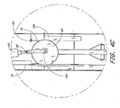
- an exercise system 200 in which the resistance unit 10 can be moved so as to vary its versatility.
- the system 200 preferably includes at least one resistance unit similar to that described above; however, various aspects, features and advantages of the system 200 can be used with other types of resistance mechanisms including, for example, but without limitation, weight stacks, hydraulics, elastic members or the like. Additionally, the illustrated exercise system 200 includes two resistance units, but one unit or more units can also be used.
- an exercise system 200 comprises a rigid station frame 202 supporting a seat assembly 204 and two resistance units 206.
- the frame can also support other exercise equipment that can be used alone or with the resistance units 206.
- Figure 5 illustrates a brace 208 that a user can hold when using the adjacent resistance unit 206.
- the station frame 202 is constructed of rigid square steel tubing. Of course, any suitable material can be used for the frame 202.
- the frame 202 has a generally U-shape as viewed from the top (see Figure 7 ) and includes a back section 210, a first side section 212 and a second side section 214.
- An upper cross member 215 links the first and second side sections 212, 214 together in order to strengthen the station frame 202.
- each side section includes a three portions: a first portion 216 that lies generally within the same plane as the back section 210, a second portion 218 that lies generally normal to the first portion 216, and a third portion 220 that extends between and lies oblique to the first and second portions 216, 218.
- An exercise area or zone 222 is defined within the first and second side sections 212, 214 and the back section 210.
- the seating assembly 204 is arranged generally centrally within the frame 202.
- the two resistance units 206 are provided on generally opposite sides of the seat assembly 204.
- Each of the resistance units 206 includes an extension mechanism 14 that provides a range of movement to the user interface 12, a resistance assembly 16 that resists movements of the user interface 12, a coupling mechanism 18 that couples the resistance assembly 16 to the extension mechanism 14, and a housing 224.
- the housing 224 supports these components and preferably encloses the resistance assembly 16, the coupling mechanism 18, and at least a portion of the extension mechanism 14.
- These mechanisms and assembly 14, 16, 18 preferably are configured and arranged in accordance with the above description of the resistance unit 10.
- the housing 224 is similar to the housing 20 of the embodiment described above; however, the housing 224 preferably has a support mechanism 226 that permits the housing 208 to move relative to the frame 202 and to be selectively locked in a position on the frame 202.
- the support mechanism 226 will be described below.
- the user interface 12 (e.g., a handle), in each of the resistance units 206, is connected to a corresponding user cable 62, as described above.
- the cable 62 is operatively connected to the resistance assembly 16 of the resistance unit 206 in the same manner as described above. As the user pulls upon the handle 12 with a force, the resistance assembly 16 applies an oppositely directed resistance force.
- the user sits or stands generally centrally in an exercise area 222 defined within the frame and grasps the handles 12 of the opposing resistance units 206. As the user pulls on the handles, the resistance units 206 resist the user's efforts with a resistance force, thus providing fitness training for the user. Alternatively, the user can use just one of the resistance units.
- the user can adjust the configuration and positioning of the seat assembly 204 and the resistance units 206. This adjustability enables the user to perform a variety of exercises that will exercise a variety of muscle groups.
- the resistance units 206 can be moved relative to the frame 202 and relative to the seat assembly 204.
- at least one arcuate track 228 is connected to the frame 202.
- pairs of arcuate tracks 228 are connected at the top and the bottom of the frame 202, and more particularly to the portions 216, 218, 220 of each side section 212, 214.
- the track pairs 228 are on opposite sides of the seat assembly 214.
- a plurality of preset holes 234 is formed through each track 228.
- a lock rod of each resistance unit 206 is configured to be selectably engageable with the holes 234 so as to fix releasably the resistance unit 206 in a specific desired position along the track 228.
- a lock rod support is mounted on the housing 224, and the lock rod extends therethrough.
- An armature connects the lock rod to a rotating control rod.
- the control rod connects the upper lock rod with a lower lock rod.
- Each lock rod is configured to engage the holes 234 in the corresponding track 228.
- the armature and rotating control rod are configured so that when the control rod rotates, the lock rods are moved into or out of the corresponding holes 234.
- the control rod extends through the housing 224. Rotation of the control rod is accomplished by manipulating a knob 236 (see Figure 5 ) on the front of the housing 224.
- the knob 236 actuates an actuator, which extends into the housing to rotate the control rod.
- a user can release the lock rods from and engage the lock rods with the corresponding holes 234 so as to move and lock the corresponding resistance unit 206 in a desired position along the tracks 228.
- various other locking mechanisms can be used to releasably secure the resistance units 206 in desired positions. For example, a friction brake, spring and ball detent, or the like can be used.
- both of the arcuate tracks 228 have a radius of approximately 84 cm (33 inches) and extend along an arcuate range of more than 90° and less than 184° (e.g., 120°). It is to be understood, however, that tracks of various sizes and configurations can also be used.
- the track can be substantially straight or can have an irregular configuration.
- the illustrated embodiment employs an upper track and a lower track. Additional embodiments can employ different configurations such as, for example, only an upper track, a single track about the midsection of the frame, three or more tracks, etc.
- Still further embodiments can employ quite different mechanisms for moving the resistance unit(s) 206.
- a rack and pinion or electromagnetic support structure can be configured to allow adjustability of the resistance unit(s).
- Any suitable member or system that allows the resistance unit(s) 206 to be easily wheeled, slid, or otherwise translated along a predefined track can advantageously be employed.
- movement of the units 206 can be controlled by hand or can be automated.
- an electric motor can be employed to move the resistance unit(s) as desired and to hold the units in place.
- a motor can be configured to move the resistance unit(s) during an exercise routine so that the user can simultaneously exercise a range of muscles.
- the seat assembly 204 comprises a seat back portion 238 and a seat bottom portion 240.
- the bottom portion 240 preferably is angled about 0-20° and more preferably about 10° relative to horizontal and includes a pedestal 242 preferably comprising three wheeled leg members.
- the back portion 238 and the bottom portion 240 are connected to each other through a linkage so that the bottom portion 240 can moved (e.g., rolled) between a plurality of seat positions, and the angle between the back 238 and bottom portion 240 will change with differing seat positions.
- a tubular vertical track, or guidepost 244 is mounted on the exercise apparatus frame 202, and more particularly to the back frame section 210, and a traveler 246 is configured to slide along the guidepost 244.
- the seat back portion 238 and linkage 248 of the seat assembly 204 are connected to the traveler 246.
- the traveler 246 As the traveler 246 is moved, the position and arrangement of the seat assembly 204 changes.
- the seat assembly 204 can be positioned out of the way of the exercise area 222 so that a user can use the exercise system 202 while standing.
- the traveler 246 can be lowered to move the seat assembly 204 into the exercise area 222 so that a user can sit on the seat assembly 204 in a partially reclined attitude while exercising.
- the seat assembly 204 can be essentially flattened out so that the user can lie on the seat assembly 204 while using the exercise system 200.
- the guidepost 244 has a number of locking holes 250 formed therethrough that define a plurality of discrete positions for seat back portion 238 on the frame 202.
- a knob 252 and locking dowel (not shown) are supported on the traveler 246, and the dowel selectively engages the locking holes 250 to releasably secure the seat assembly 204 in a variety of preset positions.
- preset seat positions may position the seat back 238 at an angle relative to horizontal of about 0° (lying down), 30°, 45°, 60°, 75° and 90° (when the seat is positioned out of the exercise area).
- a rubber stopper is used to prevent the seat back 238 from extending beyond about 0°.
- any of a multitude of mechanisms can be employed to hold the seat in a variety of positions.
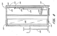
- a counterweight system 254 can be provided to assist the user while adjusting the seat position. (This system is not illustrated in Figures 6 and 7 in order to simplify these drawings.)
- the counterweight system 254 comprises a counterweight cable 256 ( Figure 8 ) attached to the seat assembly traveler 246.
- the counterweight cable 256 extends upwardly and is wound about a counterweight pulley 258 positioned atop the frame back section 210.
- the counterweight cable 256 is directed by the pulley 258 into the tubular vertical track 244, within which a counterweight rides.
- the resistance unit described above can be a floor unit, either mounted directly to the floor or to a support stand.
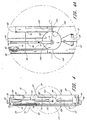
- the construction of the present resistance unit 300 is similar to that described above except for the construction of the extension mechanism and the cable guide mechanism.
- the upper pulley block 302 includes one fewer pulleys than the lower pulley block 304. In this manner, both ends of the user cable 306 extend upward as they exit the block-and-tackle mechanism 308.
- Upper pulleys 310 are disposed to either side of the extension mechanism 14 so as to guide the ends of the user cable 306 out of respective upper openings in a housing 312. This design allows for either end of the user cable 306 to be pulled (e.g., either handle 12 to be pulled) or for both cable ends to be pulled simultaneously or in a sequence.
- the housing 312 houses a resistance assembly 16 and a coupling mechanism 18.
- the construction and layout of the resistance assembly 16 and the coupling mechanism 18 are the same as that described above in connection with the first embodiment.
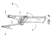
- the housing 312 also supports a pair of adjustable arms 314.
- the arms 314 are disposed on opposite sides of the housing 312 and extend outward from the housing 312.
- each arm 314 extends at a 30° angle relative to the front side 28 of the housing and thus lie 120° apart from each other.
- This arrangement is advantageous because it permits three units 300 to be mounted close to each other in a triangular arrangement. That is, each unit 300 is arranged along one leg of an equilateral triangle with the rear side of the units 300 facing one another. Because the arms 314 of each unit 300 are spaced apart by 120°, the movement of the arm 314 of one unit 300 does not interfere with the movement of an adjacent arm 314 of the next unit 300.
- Each arm 314 has a tubular structure through which the user cable 306 passes.
- the outer end of the arm supports a handle pulley assembly 316 via a hinge connection.
- the hinge connection allows the handle pulley assembly 316 to rotate about an axis of the arm 314.
- the handle pulley assembly 316 comprises a pulley that is offset to one side of the arm axis.
- the present pulley assembly 316 includes a plurality of holes, as best seen in Figure 9 , formed in its side brackets. The holes lighten the weight of the assembly 316 in order to respond more quickly to the movement of the user and to do so with less resistance.
- the first end of the user cable 306 is threaded over the pulley of the handle pulley assembly 316 and one of the handles 12 is connected to this first end of the user cable.
- the handle 12 preferably is releasably connected to the end of the user cable 306 in order to exchange different types of user interface.
- the arrangement of the hinge connection and handle pulley assembly 316 automatically aligns the user cable 306 with the handle pulley assembly 316 when the handle 12 is pulled from substantially any direction outwardly from the arm 314.
- the second end of the user cable 306 is similarly arranged and is similarly connected to the other handle 12.
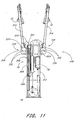
- a hinge assembly 318 hinges the opposite end of each arm 314 to the housing 312.
- Each hinge assembly 318 provides about 180° of movement (slightly less in the illustrated embodiment) in order to vary the vertical position of the corresponding handle pulley assembly 316.
- the arms 314 would be positioned to extend straight down and the user would pull the handles 12 upward from the pulley assemblies 316.
- the arms 314 would be positioned to extend straight up and the user would pull down on the handles 12.
- the arms 314 preferably can be selectively locked in a number of positions between these two extremes.
- each hinge assembly 318 includes a locking mechanism.
- each hinge assembly includes a bracket 320 that receives a lug 321.
- the bracket 320 is formed by at least two bracket plates: a front bracket plate 322 and a back bracket plate 324.
- the bracket 320 is disposed on (and preferably at least partially integrated with) the housing 312 and the lug 321 is disposed on the inner end of the arm 314.
- At least one of the bracket plates 322, 324 includes a plurality of locking holes 325 that are spaced in an arcuate pattern along an outer edge of the bracket plate.
- the lug 321 supports a knob 326 that controls a dowel (not shown). The dowel selectively engages one of the locking holes 325.
- the knob 326 is supported on the front side of the front bracket plate 322 by a support bracket 328 on the lug 321. The user pulls out the knob 326 to disengage the dowel from a locking hole 325 and releases (if a spring bias is provided) or pushes the knob 326 to engage the dowel with the locking hole 325.
- Each hinge assembly 318 includes an inner pulley 330 over which the user cable 306 runs from the corresponding upper pulley 310 into the arm 314.
- the position of the pulley 330 within the hinge assembly 318 is disposed at a position below the corresponding upper pulley 310 in the housing 312.
- the user cable 306 extends over the upper pulley 310 and under the hinge assembly pulley 330 when the arm 314 is at least in an upward extending orientation.
- Each hinge assembly 318 does not include an axle in order to accommodate the full range of movement of the arm 314 and to not pinch the user cable 306 during such movement.
- the hinge assemblies 318 also are zero-clearance (i.e., have no slop) in order that the user to does not sense any "play" in the structure as he or she pulls on the handles 12.
- the front bracket plate 322 is connected to the housing 312.
- the rear bracket plate 324 is connected to the front bracket plate 322 by fasteners 332.
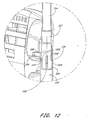
- Each bracket plate 322, 324 includes a hole 334 (the hole 334 in the front bracket 322 is covered by a shroud as seen in Figure 10A ), and the holes 334 are aligned when assembled.
- the lug 321 includes two corresponding semi-spherical dimples 335 that are arranged on opposite sides of the lug 321. As best seen in Figure 12 , a ball bearing 336 is disposed between each hole 334 and the corresponding dimple 335 such that the ball bearing 336 is captured between the corresponding bracket plate 322, 324 and the lug 321. Each ball bearing 336 has a diameter larger than the hole 334 and is sized to partially nest within the respective dimple 335. The ball bearings 336 together act as the pivot about which the arm 314 rotates. By tightening the fasteners 332 and thereby drawing the bracket plates 322, 324 together, play or looseness between the lug 321 and bracket 320 can be substantially eliminated.
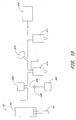
- FIG. 13 Another embodiment of a pneumatic resistance assembly allows easy adjustment of the force characteristics of the device. As discussed above, in many embodiments, it is desired to have a generally constant resistance force over an exercise stroke. However, in some instances it is desirable to be able to quickly change to a force that increases over the stroke.
- the resistance assembly 400 illustrated in Figure 13 is similar to the embodiment of the resistance assembly 16 discussed above with reference to Figures 1-4 , except that a second accumulator 402 is operatively connected to the first accumulator 404 via an air line 406, and each of the accumulators 402, 404 is about half the size of the accumulator 90 illustrated in Figure 4 .
- the first and second accumulators 402, 404 collectively function the same as the accumulator 90 of Figure 4 .
- the user can simply actuate a valve 408 in order to isolate the second accumulator 402. The effective size of the air reservoir is lessened, and the force will increase over the exercise stroke.
- the resistance assembly 400 can also communicate with a source of air pressure 410 (e.g., a compressor) through an air inlet valve 412.
- the assembly preferably includes a gauge 414 (e.g., an air pressure gauge) to indicate the amount of resistance provided by the pneumatic actuator 82.
- a bleed off valve 416 also communicates with the cylinder 84 and at least the first accumulator 404 to reduce the resistance force provided by the pneumatic cylinder 82.
- a pneumatic resistance system can comprise three or more accumulators of a plurality of sizes connected by one ore more air lines and can be selectively isolated from one another by user-actuated valves. Additionally, a valve can be interposed between the cylinder and the accumulator(s).
Claims (21)
- Appareil d'exercice comprenant :un châssis (22, 202) ;une interface utilisateur (12) mobile entre une position rétractée et une position étendue ;un actionneur pneumatique (82) ayant un cylindre (84) et une tige de piston (86) qui s'étend à partir du cylindre le long d'un axe de course, l'actionneur pneumatique étant disposé sur le châssis (22, 202) ;une roue de poulie (98) raccordée de manière rotative à la tige de piston (86) à un emplacement décalé par rapport à un centre de la roue de poulie ; etun câble (62) enroulé autour d'au moins une partie de la roue de poulie (98) et ayant une première extrémité de câble (60) et une deuxième extrémité de câble (64), la deuxième extrémité de câble (64) étant fixée sur le châssis (22, 202) et la première extrémité de câble (60) étant couplée à l'interface utilisateur (12).
- Appareil d'exercice selon la revendication 1, dans lequel la roue de poulie (98) est sensiblement circulaire.
- Appareil d'exercice selon la revendication 1, dans lequel le point décalé de fixation de la tige de piston (86) à la roue de poulie (98) se trouve du même côté de la roue de poulie (98) que la première extrémité de câble (60) au moins lorsque l'interface utilisateur (12) est dans la position rétractée, et se trouve du côté opposé de la roue de poulie (98) lorsque l'interface utilisateur est dans la position étendue.
- Appareil d'exercice selon la revendication 1, dans lequel l'actionneur pneumatique (82) est raccordé de manière pivotante au châssis (22, 202).
- Appareil d'exercice selon la revendication 4, dans lequel l'actionneur pneumatique (82) est agencé pour résister au mouvement de l'interface utilisateur (12) vers la position étendue.
- Appareil d'exercice selon la revendication 5, dans lequel une première section du câble (62) s'étend à partir de la roue de poulie (98) vers la première extrémité de câble (60) et une deuxième section du câble (62) s'étend à partir de la roue de poulie (98) vers la deuxième extrémité de câble (64), et dans lequel l'actionneur pneumatique (82) est agencé de sorte que son axe de course est généralement parallèle à la première section du câble (62) au moins lorsque l'interface utilisateur (12) est dans la position rétractée.
- Appareil d'exercice selon la revendication 6, dans lequel l'axe de course du cylindre pneumatique (84) a une orientation généralement verticale lorsque l'interface utilisateur (12) est dans la position rétractée.
- Appareil d'exercice selon la revendication 1, dans lequel l'actionneur pneumatique (82) et la roue de poulie (98) sont agencés de sorte que lorsque l'interface utilisateur (12) est dans la position rétractée, l'axe de course de l'actionneur pneumatique (82) est généralement normal par rapport à une ligne qui passe par un point central de la roue de poulie (98) et le point auquel la tige de piston (86) est fixée à la roue de poulie.
- Appareil d'exercice selon la revendication 1, comprenant en outre un guide raccordé au châssis (22, 202), le guide étant disposé à proximité de la roue de poulie (98) et agencé de sorte que la roue de poulie s'étend le long du guide.
- Appareil d'exercice selon la revendication 9, dans lequel le guide s'étend dans une direction qui est généralement parallèle à un plan qui est perpendiculaire à une face de la roue de poulie (98) et qui passe par un point central de la roue de poulie et dans lequel le guide est disposé sur un côté du plan et un point de fixation du cylindre pneumatique (84) au châssis est positionné de l'autre côté du plan.
- Appareil d'exercice selon la revendication 10, dans lequel le point auquel la tige de piston (86) est fixée à la roue de poulie (98) est du même côté du plan que le point de fixation du cylindre pneumatique (84) au châssis lorsque l'interface utilisateur (12) est dans la position rétractée.
- Appareil d'exercice selon la revendication 11, dans lequel l'axe de course de la tige de piston (86) s'étend dans une direction qui est généralement parallèle à un plan qui passe par un point central de la roue de poulie (98) et dans lequel le guide est disposé sur un côté du plan et un point de fixation de la tige de piston (86) à la roue de poulie (98) est positionné de l'autre côté du plan lorsque l'interface utilisateur est positionnée dans la position rétractée.
- Appareil d'exercice selon la revendication 1, comprenant de plus un mécanisme de palan à moufles (68, 308) fonctionnant entre l'interface utilisateur (12) et la première extrémité de câble (60), le palan à moufles étant disposé sur un côté de l'actionneur pneumatique (82) et un point auquel la deuxième extrémité de câble (64) est fixée au châssis étant disposé généralement sur un côté opposé de l'actionneur pneumatique.
- Appareil d'exercice selon la revendication 14, comprenant de plus un guide pour la roue de poulie (98) qui est raccordée au châssis, le guide étant disposé généralement du même côté de l'actionneur pneumatique (82) que la deuxième extrémité fixe (64) du câble.
- Appareil d'exercice selon la revendication 1, dans lequel au moins une partie du câble (62) est fixée sur la roue de poulie (98).
- Appareil d'exercice selon la revendication 1, comprenant de plus un système de poulie comprenant au moins un bloc de poulie auquel la première extrémité (60) du câble est fixée.
- Appareil d'exercice selon la revendication 16, dans lequel le système de poulie comprend un mécanisme de palan à moufles qui fonctionne entre l'interface utilisateur (12) et la première extrémité de câble (60), le mécanisme de palan à moufles comprenant un premier bloc ayant au moins une poulie et un deuxième bloc ayant au moins une poulie, le premier bloc étant raccordé au châssis et la première extrémité de câble étant raccordée au deuxième bloc.
- Appareil d'exercice selon la revendication 17, comprenant de plus un mécanisme de guidage de câble (46) fixé de manière mobile à et bloqué mécaniquement sur le châssis afin de modifier la position du mécanisme de guidage de câble (46) sur le châssis, le mécanisme de palan à moufles (68, 308) comprenant un câble qui est enroulé par le biais des poulies des premier et deuxième blocs, une extrémité du câble (62) passant par le mécanisme de guidage de câble (46) et raccordant l'interface utilisateur et l'extrémité opposée du câble étant fixée par rapport au mécanisme de guidage de câble (46).
- Appareil d'exercice selon la revendication 1, comprenant de plus au moins un accumulateur (402, 404, 90) en communication avec une chambre à l'intérieur du cylindre de l'actionneur pneumatique (82).
- Appareil d'exercice selon la revendication 19, comprenant de plus au moins un deuxième accumulateur, le cylindre pneumatique et les accumulateurs étant raccordés de manière opérationnelle par au moins une conduite de compensation d'air (92) afin de maintenir les pressions d'air généralement égales à l'intérieur du cylindre (84) et des accumulateurs, le deuxième accumulateur communiquant sélectivement avec le premier accumulateur et le cylindre.
- Appareil d'exercice selon la revendication 1, dans lequel le cylindre (84) comprend un corps de cylindre et un ou plusieurs capuchons d'extrémité et loge un piston de l'actionneur pneumatique (82), et dans lequel le corps de cylindre, les un ou plusieurs capuchons d'extrémité et le piston sont chacun formés à partir d'un polymère.
Applications Claiming Priority (3)
| Application Number | Priority Date | Filing Date | Title |
|---|---|---|---|
| US33246801P | 2001-11-13 | 2001-11-13 | |
| US332468P | 2001-11-13 | ||
| PCT/US2002/036383 WO2003041809A2 (fr) | 2001-11-13 | 2002-11-13 | Appareil pour exercice physique |
Publications (2)
| Publication Number | Publication Date |
|---|---|
| EP1446201A2 EP1446201A2 (fr) | 2004-08-18 |
| EP1446201B1 true EP1446201B1 (fr) | 2010-12-29 |
Family
ID=23298352
Family Applications (1)
| Application Number | Title | Priority Date | Filing Date |
|---|---|---|---|
| EP02799189A Expired - Lifetime EP1446201B1 (fr) | 2001-11-13 | 2002-11-13 | Appareil pour exercice physique |
Country Status (7)
| Country | Link |
|---|---|
| US (4) | US7172538B2 (fr) |
| EP (1) | EP1446201B1 (fr) |
| AT (1) | ATE493180T1 (fr) |
| AU (1) | AU2002363650A1 (fr) |
| CA (2) | CA2466435C (fr) |
| DE (1) | DE60238783D1 (fr) |
| WO (1) | WO2003041809A2 (fr) |
Families Citing this family (103)
| Publication number | Priority date | Publication date | Assignee | Title |
|---|---|---|---|---|
| US7169093B2 (en) * | 1999-09-14 | 2007-01-30 | Free Motion Fitness, Inc. | Cable crossover exercise apparatus |
| US7608024B2 (en) * | 2000-03-06 | 2009-10-27 | Cybex International, Inc. | Multiple exercise apparatus having an adjustable arm mechanism |
| EP1446201B1 (fr) * | 2001-11-13 | 2010-12-29 | Keiser Corporation | Appareil pour exercice physique |
| US8523789B2 (en) | 2003-06-14 | 2013-09-03 | Keiser Corporation | System for testing muscular power |
| CA2528476C (fr) * | 2003-06-27 | 2014-01-07 | Keiser Corporation | Appareil d'exercice physique comprenant un systeme de poids et une resistance pneumatique |
| US7331912B2 (en) * | 2003-06-27 | 2008-02-19 | Keiser Corporation | Adjustable bench |
| US8323158B2 (en) * | 2003-06-27 | 2012-12-04 | Keiser Corporation | Exercise apparatus using weight and pneumatic resistances |
| US7998038B2 (en) * | 2003-06-27 | 2011-08-16 | Keiser Corporation | Exercise apparatus using weight and pneumatic resistances |
| US8052584B2 (en) | 2004-04-22 | 2011-11-08 | Keiser Corporation | System and method for determining a resistance level for training a muscle group for maximum power generation |
| US7370909B2 (en) * | 2004-06-12 | 2008-05-13 | Krueger International, Inc. | Fixed seating arrangement having a swing arm shroud with a sliding shield member |
| US7601105B1 (en) * | 2005-07-11 | 2009-10-13 | Icon Ip, Inc. | Cable crossover exercise apparatus with lateral arm movement |
| US20070129223A1 (en) * | 2005-12-05 | 2007-06-07 | Joseph Kolomeir | Weight lifting simulator apparatus |
| US7569004B2 (en) * | 2005-12-05 | 2009-08-04 | Joseph Kolomeir | Weight lifting simulator apparatus |
| US8172733B1 (en) * | 2007-03-16 | 2012-05-08 | Roger Batca | Linearly adjustable multi resistance ratio exercise apparatus |
| US8834328B1 (en) * | 2007-03-16 | 2014-09-16 | Roger Batca | Adjustable flexible line ends |
| US20090131230A1 (en) * | 2007-11-21 | 2009-05-21 | Cole James A | Compact fitness center for truck sleeper compartments |
| DE102008025601B3 (de) * | 2008-05-28 | 2010-01-21 | Quattromani Engineering Gmbh | Trainingsgerät |
| US7789812B2 (en) * | 2008-09-30 | 2010-09-07 | Joseph M. Anderson | Rope climbing exercise apparatus |
| US7887471B2 (en) * | 2008-11-25 | 2011-02-15 | Mcsorley Tyrone G | Neuromuscular training apparatus and method of use |
| US7935026B2 (en) | 2008-11-25 | 2011-05-03 | Mcsorley Tyrone G | Extremity therapy apparatus |
| US20100179035A1 (en) * | 2009-01-12 | 2010-07-15 | Eric Scott Carnahan | Multipurpose Exercise Machine Utilizing Vacuum Springs |
| US8029425B2 (en) * | 2009-07-07 | 2011-10-04 | Annovium Products, Llc | Portable multipurpose whole body exercise device |
| US20120252639A1 (en) * | 2011-04-02 | 2012-10-04 | Roy Richard Simonson | Apparatus and Method for Exercising a User's Muscles |
| US8960098B2 (en) | 2012-03-13 | 2015-02-24 | Daniel Blair Boren | Trolley braking system |
| US8783190B2 (en) * | 2012-03-13 | 2014-07-22 | Daniel Blair Boren | Trolley braking system |
| EP2879764B1 (fr) | 2012-07-31 | 2017-12-13 | John Bird | Appareil, système et procédé à résistance |
| US20140121071A1 (en) * | 2012-10-31 | 2014-05-01 | Icon Health & Fitness, Inc. | Movable Pulley Systems, Methods and Devices for Exercise Machines |
| TWI477305B (zh) * | 2012-11-26 | 2015-03-21 | Honix Technology Corp | 具主動增強之半被動阻力控制系統 |
| US9381400B2 (en) | 2012-11-26 | 2016-07-05 | Honix Technology Corp. | Semi-passive resistance force control system with active augmentation |
| US9352181B2 (en) * | 2013-01-08 | 2016-05-31 | Randall O'Neil | Full body exercise machine |
| EP2969058B1 (fr) | 2013-03-14 | 2020-05-13 | Icon Health & Fitness, Inc. | Appareil d'entraînement musculaire ayant un volant, et procédés associés |
| CN103157225B (zh) * | 2013-03-22 | 2015-01-14 | 山西惠丰机械工业有限公司 | 适合中老年人的辅助健身装置 |
| US20150038300A1 (en) * | 2013-08-01 | 2015-02-05 | 2369048 Ontario Inc. | Universal fitness apparatus |
| US9205296B1 (en) | 2013-11-18 | 2015-12-08 | Douglas Paul Cook | Pneumatic sock exercise device |
| US9403047B2 (en) | 2013-12-26 | 2016-08-02 | Icon Health & Fitness, Inc. | Magnetic resistance mechanism in a cable machine |
| US9457220B2 (en) * | 2013-12-31 | 2016-10-04 | Icon Health & Fitness, Inc. | Push actuated positional adjustment of strength machines |
| EP3466497B1 (fr) * | 2014-02-28 | 2020-08-05 | Hoist Fitness Systems, Inc. | Übungsmaschine mit funktionellem trainer |
| US10426989B2 (en) | 2014-06-09 | 2019-10-01 | Icon Health & Fitness, Inc. | Cable system incorporated into a treadmill |
| USD737387S1 (en) * | 2014-08-04 | 2015-08-25 | Brudden Equipamentos Ltda. | Exercise weight holder |
| USD746388S1 (en) * | 2014-08-28 | 2015-12-29 | Hoist Fitness Systems, Inc. | Exercise machine |
| US20160121156A1 (en) | 2014-10-31 | 2016-05-05 | James Christopher Bach | Exercise device |
| DE102014223435A1 (de) * | 2014-11-17 | 2016-05-19 | F&K Reinhold Ferstl Markus Knestel GbR (vertr. Gesellschafter Herr Dr. Markus Knestel, 87496 Hopferbach) | Trainingsvorrichtung mit 3D-Positionserfassung und deren Betriebsverfahren |
| WO2016185288A2 (fr) * | 2015-05-20 | 2016-11-24 | Pérez Gómez José Miguel | Appareil d'entraînement physique |
| US10709924B2 (en) | 2015-06-19 | 2020-07-14 | Flexline Fitness, Inc. | Squat bar for fitness machine |
| TWI644702B (zh) | 2015-08-26 | 2018-12-21 | 美商愛康運動與健康公司 | 力量運動機械裝置 |
| US10940360B2 (en) | 2015-08-26 | 2021-03-09 | Icon Health & Fitness, Inc. | Strength exercise mechanisms |
| GB2541725B (en) * | 2015-08-28 | 2018-01-03 | Flak Ltd | Weights system |
| US20190118022A1 (en) * | 2015-09-02 | 2019-04-25 | Marcus Carter | Gym cage |
| WO2017152275A1 (fr) * | 2016-03-07 | 2017-09-14 | 9614206 Canada Inc. | Appareil d'exercice |
| US10441840B2 (en) | 2016-03-18 | 2019-10-15 | Icon Health & Fitness, Inc. | Collapsible strength exercise machine |
| US10293211B2 (en) | 2016-03-18 | 2019-05-21 | Icon Health & Fitness, Inc. | Coordinated weight selection |
| US10252109B2 (en) | 2016-05-13 | 2019-04-09 | Icon Health & Fitness, Inc. | Weight platform treadmill |
| USD807445S1 (en) | 2016-08-12 | 2018-01-09 | Nautilus, Inc. | Exercise machine |
| JP6944206B2 (ja) | 2016-08-17 | 2021-10-06 | 9614206 カナダ インコーポレイテッド | 抵抗発生装置、運動器具及び方法 |
| US10072743B1 (en) | 2016-09-02 | 2018-09-11 | Michael Brian Wittig | Rotary-to-linear transmission system |
| US10661114B2 (en) | 2016-11-01 | 2020-05-26 | Icon Health & Fitness, Inc. | Body weight lift mechanism on treadmill |
| KR101794094B1 (ko) * | 2016-11-15 | 2017-11-07 | 주식회사 플라이업 | 공압을 이용한 근력운동기구 |
| CN108283792B (zh) * | 2017-01-10 | 2023-10-17 | 南通铁人运动用品有限公司 | 勾腿训练器 |
| CN108283791A (zh) * | 2017-01-10 | 2018-07-17 | 南通铁人运动用品有限公司 | 下蹲训练器 |
| CN108283774A (zh) * | 2017-01-10 | 2018-07-17 | 南通铁人运动用品有限公司 | 恒阻力气动箱 |
| US11097148B2 (en) * | 2017-07-13 | 2021-08-24 | Flexline Fitness, Inc. | Fitness machine |
| AU2019231690B2 (en) | 2018-03-06 | 2022-07-14 | Coulter Ventures Llc | Adjustable carriage assembly for pivotable arm for weight rack |
| USD905179S1 (en) * | 2018-03-28 | 2020-12-15 | Flexline Fitness, Inc. | Exercise kiosk |
| RU2754906C1 (ru) * | 2018-04-11 | 2021-09-08 | Джим-Ин-Э-Бокс Ллк | Многофункциональный универсальный силовой комплекс |
| WO2019217447A1 (fr) | 2018-05-07 | 2019-11-14 | Coulter Ventures Llc | Machine d'haltérophilie |
| USD854637S1 (en) | 2018-05-07 | 2019-07-23 | Coulter Ventures, LLC | Exercise stand |
| US11331538B2 (en) * | 2018-08-07 | 2022-05-17 | Interactive Strength, Inc. | Interactive exercise machine data architecture |
| US11426618B2 (en) * | 2018-08-14 | 2022-08-30 | Tonal Systems, Inc. | Racking and unracking exercise machine |
| US20200061413A1 (en) * | 2018-08-22 | 2020-02-27 | Michael David Cook | Fitness and Rehabilitation machine for the Rotator Cuff |
| USD898136S1 (en) | 2018-08-27 | 2020-10-06 | Coulter Ventures, Llc. | Implement for exercise rack |
| USD890867S1 (en) | 2018-08-27 | 2020-07-21 | Coulter Ventures, Llc. | Carriage for exercise rack |
| USD890271S1 (en) | 2018-08-27 | 2020-07-14 | Coulter Ventures, Llc. | Carriage for exercise rack |
| USD898137S1 (en) | 2018-08-30 | 2020-10-06 | Coulter Ventures, Llc. | Implement for exercise rack |
| USD921132S1 (en) | 2018-10-04 | 2021-06-01 | Tonal Systems, Inc. | Exercise machine |
| USD912168S1 (en) * | 2018-10-04 | 2021-03-02 | Tonal Systems, Inc. | Exercise machine |
| EP3863737A1 (fr) | 2018-10-12 | 2021-08-18 | Coulter Ventures, LLC | Machine d'haltérophilie |
| USD903793S1 (en) | 2018-10-17 | 2020-12-01 | Coulter Ventures, Llc. | Pulley housing |
| USD892239S1 (en) | 2018-10-19 | 2020-08-04 | Coulter Ventures, Llc. | Handle bracket |
| USD893639S1 (en) | 2018-10-25 | 2020-08-18 | Coulter Ventures, Llc. | Pulley housing |
| US10661141B1 (en) * | 2019-02-27 | 2020-05-26 | Athletic Technologies LLC | Tackling apparatus |
| USD1013804S1 (en) | 2019-05-21 | 2024-02-06 | Coulter Ventures, Llc. | Weightlifting machine |
| USD928254S1 (en) | 2019-08-22 | 2021-08-17 | Coulter Ventures, Llc. | Weight support |
| USD920451S1 (en) * | 2019-08-30 | 2021-05-25 | Rep Fitness, LLC | Accessory for weightlifting equipment |
| USD937367S1 (en) * | 2020-02-03 | 2021-11-30 | Interactive Strength, Inc. | Exercise device |
| USD937368S1 (en) * | 2020-02-03 | 2021-11-30 | Interactive Strength, Inc. | Exercise device |
| USD946674S1 (en) * | 2020-02-10 | 2022-03-22 | Interactive Strength, Inc. | Exercise device |
| USD946673S1 (en) * | 2020-02-10 | 2022-03-22 | Interactive Strength, Inc. | Exercise device |
| WO2022020439A1 (fr) | 2020-07-21 | 2022-01-27 | Aspen Integrative Kinetics, LLC | Appareil d'exercice et ses procédés de fonctionnement |
| WO2022026464A1 (fr) | 2020-07-28 | 2022-02-03 | Tonal Systems, Inc. | Poignées d'utilisateur plus intelligentes pour appareil d'exercice |
| US11731000B2 (en) * | 2020-08-14 | 2023-08-22 | Wesley Beecroft | Fly wheel resistance workout system |
| USD1012673S1 (en) | 2021-02-19 | 2024-01-30 | Coulter Ventures, Llc. | Pulley |
| USD1015125S1 (en) | 2021-02-19 | 2024-02-20 | Coulter Ventures, Llc. | Pulley |
| RU207162U1 (ru) * | 2021-06-28 | 2021-10-14 | Константин Владимирович Калинин | Каретка тренажера |
| EP4122553A1 (fr) * | 2021-07-23 | 2023-01-25 | LITE SPORT S.r.l. | Équipement pneumatique pour l'entraînement physique |
| CA3233845A1 (fr) | 2021-10-07 | 2023-04-13 | Keiser Corporation | Systeme et procede de determination d'endurance d'un groupe musculaire |
| USD1015450S1 (en) | 2021-12-22 | 2024-02-20 | Tonal Systems, Inc. | Exercise machine component |
| USD1015448S1 (en) | 2021-12-22 | 2024-02-20 | Tonal Systems, Inc. | Exercise machine |
| USD1015449S1 (en) | 2021-12-22 | 2024-02-20 | Tonal Systems, Inc. | Exercise machine |
| USD1017741S1 (en) | 2022-01-07 | 2024-03-12 | Rep Fitness Llc | Shroud for weight stack |
| USD1025247S1 (en) | 2022-01-07 | 2024-04-30 | Rep Fitness, LLC | Weightlifting system |
| WO2023150853A1 (fr) * | 2022-02-10 | 2023-08-17 | Celano Pereira Leandro | Système mécanique-pneumatique avec poulies de divers diamètres et piston pneumatique à pression fixe pour le changement de résistance dans des équipements de musculation et équipement de musculation |
| USD1022088S1 (en) * | 2022-06-17 | 2024-04-09 | Rotem Cooper | Exercise machine arm joint |
| CN115414638B (zh) * | 2022-09-22 | 2023-12-15 | 青岛英派斯健康科技股份有限公司 | 一种大行程阻力训练器 |
Family Cites Families (58)
| Publication number | Priority date | Publication date | Assignee | Title |
|---|---|---|---|---|
| US325404A (en) * | 1885-09-01 | forest | ||
| US1015071A (en) * | 1911-08-28 | 1912-01-16 | Robert Reach | Gymnasium rowing apparatus. |
| US2932509A (en) * | 1957-08-02 | 1960-04-12 | Zinkin Harold | Body exercising apparatus |
| US3074716A (en) * | 1960-07-26 | 1963-01-22 | Carl E Mitchel | Swimming instructing machine and exerciser |
| US3387843A (en) * | 1964-08-19 | 1968-06-11 | Lloyd E. Chandler | Exercise machine in which the user pushes or pulls against a resisting force produced by a pneumatic cylinder operating in conjunction with compressed air |
| US3385590A (en) * | 1965-02-05 | 1968-05-28 | Girling Ltd | Vehicle suspension assemblies |
| US3451271A (en) * | 1966-06-30 | 1969-06-24 | David E Knoblauch | Hydraulically controlled exercising and weight lifting device |
| US3515248A (en) * | 1968-03-28 | 1970-06-02 | Westinghouse Air Brake Co | Railway car wheel tread brake apparatus |
| US3822599A (en) * | 1969-10-16 | 1974-07-09 | J Brentham | Exercising device |
| US3692296A (en) * | 1970-12-16 | 1972-09-19 | Monroe Auto Equipment Co | Air spring shock absorber unit |
| US3692596A (en) * | 1971-03-02 | 1972-09-19 | Robert William Fraser | Dispersion strengthened nickel-chromium alloys |
| US3784194A (en) * | 1972-04-20 | 1974-01-08 | J Perrine | Bilateral reciprocal isokinetic exerciser |
| US4256302A (en) * | 1976-03-10 | 1981-03-17 | Keiser Dennis L | Variable resistance exercising device |
| US4050310A (en) * | 1976-03-17 | 1977-09-27 | Keiser Dennis L | Exercising apparatus |
| US4257593A (en) * | 1977-12-20 | 1981-03-24 | Keiser Corporation | Pneumatic exercising device |
| US4227689A (en) * | 1978-07-24 | 1980-10-14 | Kintron, Incorporated | Exercising device including linkage for control of muscular exertion required through exercising stroke |
| US4326707A (en) * | 1978-09-27 | 1982-04-27 | Strecker Dennis C | Hydraulic exerciser |
| US4247098A (en) * | 1978-12-11 | 1981-01-27 | Brentham Jerry D | Dual cylinder hip exercising device |
| US4722525A (en) * | 1979-02-16 | 1988-02-02 | Brentham Jerry D | Physical fitness diagnostic testing apparatus |
| US4609190A (en) * | 1983-05-18 | 1986-09-02 | Brentham Jerry D | Physical fitness diagnostic testing apparatus |
| US4500089A (en) * | 1983-01-20 | 1985-02-19 | Nautilus Sports/Medical Industries, Inc. | Weight lifting lower back exercising machine |
| US4549733A (en) * | 1983-02-04 | 1985-10-29 | Alan Salyer | Weight type exercising device |
| US4730829A (en) * | 1984-11-27 | 1988-03-15 | The Toro Company | Exercise machine |
| US4720099A (en) * | 1984-11-27 | 1988-01-19 | The Toro Company | Exercise machine |
| FR2581550B1 (fr) | 1985-05-10 | 1989-06-30 | Jaquet Hugues | Appareil de musculation |
| US4700946A (en) * | 1985-10-11 | 1987-10-20 | Breunig Donald E | Exercise Device |
| US4911436A (en) * | 1987-04-29 | 1990-03-27 | Pneu-Body, Inc. | Pneumatic home fitness center |
| US4915379A (en) * | 1988-07-21 | 1990-04-10 | Sapp William E | Apparatus for exercise and physical therapy |
| FR2645032A1 (fr) | 1989-03-31 | 1990-10-05 | Design Corporel | Dispositif d'exercice musculaire equipe d'un verin pneumatique |
| US5114389A (en) * | 1989-06-23 | 1992-05-19 | Brentham Jerry D | Stair climber exercise device |
| US4976426A (en) * | 1989-09-06 | 1990-12-11 | Garden Reach Developments Ltd. | Rehabilitation exercise device |
| FI86509C (fi) * | 1990-02-07 | 1992-09-10 | Tunturipyoerae Oy | Traeningsanordning. |
| US5403257A (en) * | 1990-02-07 | 1995-04-04 | Tunturipyora Oy | Multi-pull exercise devices |
| US5044632A (en) * | 1990-04-26 | 1991-09-03 | Hammer Corporation | Dumbbell press exercise machine |
| US5158516A (en) * | 1990-06-28 | 1992-10-27 | Johnson William S | Invalid gravity force rebound exerciser |
| US5018725A (en) * | 1990-07-25 | 1991-05-28 | Cook Roger D | Adjustable exercise equipment |
| US5060939A (en) * | 1990-10-01 | 1991-10-29 | Diversified Products Corporation | Multi-position exercise bench |
| US5102122A (en) * | 1990-10-02 | 1992-04-07 | Robert A. Piane, Jr. | Exercise apparatus |
| US5312315A (en) * | 1990-12-21 | 1994-05-17 | Core Outpatient Services | Pneumatic variable resistance rehabilitation/therapy apparatus |
| US5145479A (en) * | 1991-04-03 | 1992-09-08 | Brad Olschansky | Total body exercising apparatus |
| US5336145A (en) * | 1991-08-30 | 1994-08-09 | Keiser Dennis L | Apparatus having a movable load bearing surface |
| US5310394A (en) * | 1992-12-28 | 1994-05-10 | Demetrios Kallios | Spotter system for weightlifters |
| US5526692A (en) * | 1993-12-29 | 1996-06-18 | Keiser Corporation | Sensor |
| CA2170720A1 (fr) * | 1995-03-15 | 1996-09-16 | Keiser Corporation | Appareil d'exercices physiques |
| US5558607A (en) * | 1995-09-12 | 1996-09-24 | Darling; Thomas G. | Training device for martial art athletes |
| US5890996A (en) * | 1996-05-30 | 1999-04-06 | Interactive Performance Monitoring, Inc. | Exerciser and physical performance monitoring system |
| US5776040A (en) | 1996-08-02 | 1998-07-07 | Nautilus International, Inc. | Auxiliary weight system for exercise apparatus |
| JP3746390B2 (ja) * | 1998-07-23 | 2006-02-15 | 建昇 李 | 運動器材の負荷装置 |
| US6142919A (en) * | 1999-04-12 | 2000-11-07 | Jorgensen; Adam A. | Multi-purpose low profile physical exercising device |
| US7169093B2 (en) * | 1999-09-14 | 2007-01-30 | Free Motion Fitness, Inc. | Cable crossover exercise apparatus |
| US6447430B1 (en) | 2000-02-10 | 2002-09-10 | Nautilus, Inc. | Exercise machine |
| US7608024B2 (en) * | 2000-03-06 | 2009-10-27 | Cybex International, Inc. | Multiple exercise apparatus having an adjustable arm mechanism |
| US6352493B1 (en) * | 2000-08-29 | 2002-03-05 | James Davis | Swimming simulation system |
| US20070161470A1 (en) * | 2001-11-03 | 2007-07-12 | Berryman Thomas J | Golf swing muscle strengthener |
| EP1446201B1 (fr) * | 2001-11-13 | 2010-12-29 | Keiser Corporation | Appareil pour exercice physique |
| US7094185B2 (en) * | 2002-01-17 | 2006-08-22 | Darrell Greenland | Versatile exercise machine |
| US7892155B2 (en) * | 2005-01-14 | 2011-02-22 | Nautilus, Inc. | Exercise device |
| US7601105B1 (en) * | 2005-07-11 | 2009-10-13 | Icon Ip, Inc. | Cable crossover exercise apparatus with lateral arm movement |
-
2002
- 2002-11-13 EP EP02799189A patent/EP1446201B1/fr not_active Expired - Lifetime
- 2002-11-13 CA CA002466435A patent/CA2466435C/fr not_active Expired - Lifetime
- 2002-11-13 WO PCT/US2002/036383 patent/WO2003041809A2/fr not_active Application Discontinuation
- 2002-11-13 CA CA2651831A patent/CA2651831C/fr not_active Expired - Lifetime
- 2002-11-13 DE DE60238783T patent/DE60238783D1/de not_active Expired - Lifetime
- 2002-11-13 AT AT02799189T patent/ATE493180T1/de not_active IP Right Cessation
- 2002-11-13 AU AU2002363650A patent/AU2002363650A1/en not_active Abandoned
- 2002-11-13 US US10/294,476 patent/US7172538B2/en not_active Expired - Lifetime
-
2007
- 2007-01-30 US US11/669,030 patent/US7686749B2/en not_active Expired - Lifetime
-
2010
- 2010-01-29 US US12/697,103 patent/US7955235B2/en not_active Expired - Fee Related
-
2011
- 2011-06-07 US US13/155,183 patent/US20110245049A1/en not_active Abandoned
Also Published As
| Publication number | Publication date |
|---|---|
| EP1446201A2 (fr) | 2004-08-18 |
| US7686749B2 (en) | 2010-03-30 |
| AU2002363650A1 (en) | 2003-05-26 |
| DE60238783D1 (de) | 2011-02-10 |
| US7955235B2 (en) | 2011-06-07 |
| WO2003041809A2 (fr) | 2003-05-22 |
| US7172538B2 (en) | 2007-02-06 |
| US20110245049A1 (en) | 2011-10-06 |
| CA2651831C (fr) | 2012-05-15 |
| US20030115955A1 (en) | 2003-06-26 |
| CA2466435C (fr) | 2009-03-17 |
| CA2466435A1 (fr) | 2003-05-22 |
| CA2651831A1 (fr) | 2003-05-22 |
| ATE493180T1 (de) | 2011-01-15 |
| WO2003041809A3 (fr) | 2004-02-19 |
| US20070123400A1 (en) | 2007-05-31 |
| US20100137114A1 (en) | 2010-06-03 |
Similar Documents
| Publication | Publication Date | Title |
|---|---|---|
| EP1446201B1 (fr) | Appareil pour exercice physique | |
| US7998038B2 (en) | Exercise apparatus using weight and pneumatic resistances | |
| US8323158B2 (en) | Exercise apparatus using weight and pneumatic resistances | |
| US10265572B2 (en) | Exercise device | |
| US6592498B1 (en) | Exercise devices | |
| US7608024B2 (en) | Multiple exercise apparatus having an adjustable arm mechanism | |
| US7998036B2 (en) | Functional training exercise apparatus and methods | |
| US4685670A (en) | Elastic tension exercising apparatus with multiple pass cable and pulley | |
| US7695418B2 (en) | Exercise bench assemblies having wheels with integral brakes | |
| US6652426B2 (en) | Exercise Machine | |
| US20050272577A1 (en) | Exercise apparatus with differential arm resistance assembly | |
| US20080188361A1 (en) | Multi-function weight training apparatus | |
| CN105744992A (zh) | 施加自适应阻力的锻炼装置 | |
| US20080051269A1 (en) | Exercise Assemblies Having Foot-Retaining Apparatus | |
| WO1998042411A1 (fr) | Appareils d'exercices | |
| EP1648571B1 (fr) | Appareil d'exercice physique comprenant des systèmes de résistance à poid et pneumatique | |
| US7846075B2 (en) | Exercise assemblies having self-adjusting pad devices | |
| US20230338770A1 (en) | Rope pull training device | |
| GB2335609A (en) | Multi-directional exercise apparatus | |
| GB2372461A (en) | Multi-directional exercising apparatus |
Legal Events
| Date | Code | Title | Description |
|---|---|---|---|
| PUAI | Public reference made under article 153(3) epc to a published international application that has entered the european phase |
Free format text: ORIGINAL CODE: 0009012 |
|
| 17P | Request for examination filed |
Effective date: 20040609 |
|
| AK | Designated contracting states |
Kind code of ref document: A2 Designated state(s): AT BE BG CH CY CZ DE DK EE ES FI FR GB GR IE IT LI LU MC NL PT SE SK TR |
|
| AX | Request for extension of the european patent |
Extension state: AL LT LV MK RO SI |
|
| 17Q | First examination report despatched |
Effective date: 20091029 |
|
| GRAP | Despatch of communication of intention to grant a patent |
Free format text: ORIGINAL CODE: EPIDOSNIGR1 |
|
| GRAS | Grant fee paid |
Free format text: ORIGINAL CODE: EPIDOSNIGR3 |
|
| GRAA | (expected) grant |
Free format text: ORIGINAL CODE: 0009210 |
|
| AK | Designated contracting states |
Kind code of ref document: B1 Designated state(s): AT BE BG CH CY CZ DE DK EE ES FI FR GB GR IE IT LI LU MC NL PT SE SK TR |
|
| REG | Reference to a national code |
Ref country code: GB Ref legal event code: FG4D |
|
| REG | Reference to a national code |
Ref country code: CH Ref legal event code: EP |
|
| REG | Reference to a national code |
Ref country code: IE Ref legal event code: FG4D |
|
| REF | Corresponds to: |
Ref document number: 60238783 Country of ref document: DE Date of ref document: 20110210 Kind code of ref document: P |
|
| REG | Reference to a national code |
Ref country code: DE Ref legal event code: R096 Ref document number: 60238783 Country of ref document: DE Effective date: 20110210 |
|
| REG | Reference to a national code |
Ref country code: NL Ref legal event code: T3 |
|
| PG25 | Lapsed in a contracting state [announced via postgrant information from national office to epo] |
Ref country code: SE Free format text: LAPSE BECAUSE OF FAILURE TO SUBMIT A TRANSLATION OF THE DESCRIPTION OR TO PAY THE FEE WITHIN THE PRESCRIBED TIME-LIMIT Effective date: 20101229 Ref country code: BG Free format text: LAPSE BECAUSE OF FAILURE TO SUBMIT A TRANSLATION OF THE DESCRIPTION OR TO PAY THE FEE WITHIN THE PRESCRIBED TIME-LIMIT Effective date: 20110329 Ref country code: CY Free format text: LAPSE BECAUSE OF FAILURE TO SUBMIT A TRANSLATION OF THE DESCRIPTION OR TO PAY THE FEE WITHIN THE PRESCRIBED TIME-LIMIT Effective date: 20101229 Ref country code: FI Free format text: LAPSE BECAUSE OF FAILURE TO SUBMIT A TRANSLATION OF THE DESCRIPTION OR TO PAY THE FEE WITHIN THE PRESCRIBED TIME-LIMIT Effective date: 20101229 Ref country code: AT Free format text: LAPSE BECAUSE OF FAILURE TO SUBMIT A TRANSLATION OF THE DESCRIPTION OR TO PAY THE FEE WITHIN THE PRESCRIBED TIME-LIMIT Effective date: 20101229 |
|
| PG25 | Lapsed in a contracting state [announced via postgrant information from national office to epo] |
Ref country code: PT Free format text: LAPSE BECAUSE OF FAILURE TO SUBMIT A TRANSLATION OF THE DESCRIPTION OR TO PAY THE FEE WITHIN THE PRESCRIBED TIME-LIMIT Effective date: 20110429 Ref country code: ES Free format text: LAPSE BECAUSE OF FAILURE TO SUBMIT A TRANSLATION OF THE DESCRIPTION OR TO PAY THE FEE WITHIN THE PRESCRIBED TIME-LIMIT Effective date: 20110409 Ref country code: CZ Free format text: LAPSE BECAUSE OF FAILURE TO SUBMIT A TRANSLATION OF THE DESCRIPTION OR TO PAY THE FEE WITHIN THE PRESCRIBED TIME-LIMIT Effective date: 20101229 Ref country code: EE Free format text: LAPSE BECAUSE OF FAILURE TO SUBMIT A TRANSLATION OF THE DESCRIPTION OR TO PAY THE FEE WITHIN THE PRESCRIBED TIME-LIMIT Effective date: 20101229 Ref country code: BE Free format text: LAPSE BECAUSE OF FAILURE TO SUBMIT A TRANSLATION OF THE DESCRIPTION OR TO PAY THE FEE WITHIN THE PRESCRIBED TIME-LIMIT Effective date: 20101229 Ref country code: GR Free format text: LAPSE BECAUSE OF FAILURE TO SUBMIT A TRANSLATION OF THE DESCRIPTION OR TO PAY THE FEE WITHIN THE PRESCRIBED TIME-LIMIT Effective date: 20110330 |
|
| PG25 | Lapsed in a contracting state [announced via postgrant information from national office to epo] |
Ref country code: SK Free format text: LAPSE BECAUSE OF FAILURE TO SUBMIT A TRANSLATION OF THE DESCRIPTION OR TO PAY THE FEE WITHIN THE PRESCRIBED TIME-LIMIT Effective date: 20101229 |
|
| PG25 | Lapsed in a contracting state [announced via postgrant information from national office to epo] |
Ref country code: DK Free format text: LAPSE BECAUSE OF FAILURE TO SUBMIT A TRANSLATION OF THE DESCRIPTION OR TO PAY THE FEE WITHIN THE PRESCRIBED TIME-LIMIT Effective date: 20101229 |
|
| PLBE | No opposition filed within time limit |
Free format text: ORIGINAL CODE: 0009261 |
|
| STAA | Information on the status of an ep patent application or granted ep patent |
Free format text: STATUS: NO OPPOSITION FILED WITHIN TIME LIMIT |
|
| 26N | No opposition filed |
Effective date: 20110930 |
|
| REG | Reference to a national code |
Ref country code: DE Ref legal event code: R097 Ref document number: 60238783 Country of ref document: DE Effective date: 20110930 |
|
| PG25 | Lapsed in a contracting state [announced via postgrant information from national office to epo] |
Ref country code: IT Free format text: LAPSE BECAUSE OF FAILURE TO SUBMIT A TRANSLATION OF THE DESCRIPTION OR TO PAY THE FEE WITHIN THE PRESCRIBED TIME-LIMIT Effective date: 20101229 |
|
| PG25 | Lapsed in a contracting state [announced via postgrant information from national office to epo] |
Ref country code: MC Free format text: LAPSE BECAUSE OF NON-PAYMENT OF DUE FEES Effective date: 20111130 |
|
| REG | Reference to a national code |
Ref country code: CH Ref legal event code: PL |
|
| PG25 | Lapsed in a contracting state [announced via postgrant information from national office to epo] |
Ref country code: CH Free format text: LAPSE BECAUSE OF NON-PAYMENT OF DUE FEES Effective date: 20111130 Ref country code: LI Free format text: LAPSE BECAUSE OF NON-PAYMENT OF DUE FEES Effective date: 20111130 |
|
| REG | Reference to a national code |
Ref country code: IE Ref legal event code: MM4A |
|
| PG25 | Lapsed in a contracting state [announced via postgrant information from national office to epo] |
Ref country code: IE Free format text: LAPSE BECAUSE OF NON-PAYMENT OF DUE FEES Effective date: 20111113 |
|
| PG25 | Lapsed in a contracting state [announced via postgrant information from national office to epo] |
Ref country code: LU Free format text: LAPSE BECAUSE OF NON-PAYMENT OF DUE FEES Effective date: 20111113 |
|
| PG25 | Lapsed in a contracting state [announced via postgrant information from national office to epo] |
Ref country code: TR Free format text: LAPSE BECAUSE OF FAILURE TO SUBMIT A TRANSLATION OF THE DESCRIPTION OR TO PAY THE FEE WITHIN THE PRESCRIBED TIME-LIMIT Effective date: 20101229 |
|
| REG | Reference to a national code |
Ref country code: DE Ref legal event code: R082 Ref document number: 60238783 Country of ref document: DE Representative=s name: FLEISCHER, ENGELS & PARTNER MBB, PATENTANWAELT, DE |
|
| REG | Reference to a national code |
Ref country code: FR Ref legal event code: PLFP Year of fee payment: 14 |
|
| REG | Reference to a national code |
Ref country code: FR Ref legal event code: PLFP Year of fee payment: 15 |
|
| REG | Reference to a national code |
Ref country code: FR Ref legal event code: PLFP Year of fee payment: 16 |
|
| REG | Reference to a national code |
Ref country code: FR Ref legal event code: PLFP Year of fee payment: 17 |
|
| PGFP | Annual fee paid to national office [announced via postgrant information from national office to epo] |
Ref country code: FR Payment date: 20210930 Year of fee payment: 20 |
|
| PGFP | Annual fee paid to national office [announced via postgrant information from national office to epo] |
Ref country code: GB Payment date: 20210922 Year of fee payment: 20 |
|
| PGFP | Annual fee paid to national office [announced via postgrant information from national office to epo] |
Ref country code: NL Payment date: 20211014 Year of fee payment: 20 |
|
| PGFP | Annual fee paid to national office [announced via postgrant information from national office to epo] |
Ref country code: DE Payment date: 20210923 Year of fee payment: 20 |
|
| REG | Reference to a national code |
Ref country code: DE Ref legal event code: R071 Ref document number: 60238783 Country of ref document: DE |
|
| REG | Reference to a national code |
Ref country code: NL Ref legal event code: MK Effective date: 20221112 |
|
| REG | Reference to a national code |
Ref country code: GB Ref legal event code: PE20 Expiry date: 20221112 |
|
| PG25 | Lapsed in a contracting state [announced via postgrant information from national office to epo] |
Ref country code: GB Free format text: LAPSE BECAUSE OF EXPIRATION OF PROTECTION Effective date: 20221112 |