EP1445989A1 - Schaltungsanordnung und Verfahren für eine Beleuchtungseinrichtung mit einstellbarer Farbe und Helligkeit - Google Patents
Schaltungsanordnung und Verfahren für eine Beleuchtungseinrichtung mit einstellbarer Farbe und Helligkeit Download PDFInfo
- Publication number
- EP1445989A1 EP1445989A1 EP04000340A EP04000340A EP1445989A1 EP 1445989 A1 EP1445989 A1 EP 1445989A1 EP 04000340 A EP04000340 A EP 04000340A EP 04000340 A EP04000340 A EP 04000340A EP 1445989 A1 EP1445989 A1 EP 1445989A1
- Authority
- EP
- European Patent Office
- Prior art keywords
- light sources
- group
- lighting device
- con
- color
- Prior art date
- Legal status (The legal status is an assumption and is not a legal conclusion. Google has not performed a legal analysis and makes no representation as to the accuracy of the status listed.)
- Granted
Links
Images


Classifications
-
- H—ELECTRICITY
- H05—ELECTRIC TECHNIQUES NOT OTHERWISE PROVIDED FOR
- H05B—ELECTRIC HEATING; ELECTRIC LIGHT SOURCES NOT OTHERWISE PROVIDED FOR; CIRCUIT ARRANGEMENTS FOR ELECTRIC LIGHT SOURCES, IN GENERAL
- H05B45/00—Circuit arrangements for operating light-emitting diodes [LED]
- H05B45/20—Controlling the colour of the light
- H05B45/24—Controlling the colour of the light using electrical feedback from LEDs or from LED modules
-
- A—HUMAN NECESSITIES
- A01—AGRICULTURE; FORESTRY; ANIMAL HUSBANDRY; HUNTING; TRAPPING; FISHING
- A01K—ANIMAL HUSBANDRY; AVICULTURE; APICULTURE; PISCICULTURE; FISHING; REARING OR BREEDING ANIMALS, NOT OTHERWISE PROVIDED FOR; NEW BREEDS OF ANIMALS
- A01K97/00—Accessories for angling
- A01K97/04—Containers for bait; Preparation of bait
-
- A—HUMAN NECESSITIES
- A01—AGRICULTURE; FORESTRY; ANIMAL HUSBANDRY; HUNTING; TRAPPING; FISHING
- A01K—ANIMAL HUSBANDRY; AVICULTURE; APICULTURE; PISCICULTURE; FISHING; REARING OR BREEDING ANIMALS, NOT OTHERWISE PROVIDED FOR; NEW BREEDS OF ANIMALS
- A01K97/00—Accessories for angling
- A01K97/06—Containers or holders for hooks, lines, sinkers, flies or the like
-
- H—ELECTRICITY
- H05—ELECTRIC TECHNIQUES NOT OTHERWISE PROVIDED FOR
- H05B—ELECTRIC HEATING; ELECTRIC LIGHT SOURCES NOT OTHERWISE PROVIDED FOR; CIRCUIT ARRANGEMENTS FOR ELECTRIC LIGHT SOURCES, IN GENERAL
- H05B45/00—Circuit arrangements for operating light-emitting diodes [LED]
- H05B45/20—Controlling the colour of the light
-
- H—ELECTRICITY
- H05—ELECTRIC TECHNIQUES NOT OTHERWISE PROVIDED FOR
- H05B—ELECTRIC HEATING; ELECTRIC LIGHT SOURCES NOT OTHERWISE PROVIDED FOR; CIRCUIT ARRANGEMENTS FOR ELECTRIC LIGHT SOURCES, IN GENERAL
- H05B45/00—Circuit arrangements for operating light-emitting diodes [LED]
- H05B45/30—Driver circuits
- H05B45/37—Converter circuits
-
- Y—GENERAL TAGGING OF NEW TECHNOLOGICAL DEVELOPMENTS; GENERAL TAGGING OF CROSS-SECTIONAL TECHNOLOGIES SPANNING OVER SEVERAL SECTIONS OF THE IPC; TECHNICAL SUBJECTS COVERED BY FORMER USPC CROSS-REFERENCE ART COLLECTIONS [XRACs] AND DIGESTS
- Y02—TECHNOLOGIES OR APPLICATIONS FOR MITIGATION OR ADAPTATION AGAINST CLIMATE CHANGE
- Y02B—CLIMATE CHANGE MITIGATION TECHNOLOGIES RELATED TO BUILDINGS, e.g. HOUSING, HOUSE APPLIANCES OR RELATED END-USER APPLICATIONS
- Y02B20/00—Energy efficient lighting technologies, e.g. halogen lamps or gas discharge lamps
- Y02B20/30—Semiconductor lamps, e.g. solid state lamps [SSL] light emitting diodes [LED] or organic LED [OLED]
Definitions
- the invention relates to a circuit arrangement according to the preamble of Claim 1. It is in particular a circuit arrangement that the setting of both the color and the brightness in a lighting device of emitted light.
- the color of a light source is generally determined using a standard color chart.
- This standard color chart is in the DIN standard 5033 or defined in the equivalent international standard CIE 1931.
- a standard color chart defines a color using an x and a y coordinate.
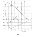
- Figure 1 is shown a standard color chart. All colors visible to a human lie within a color triangle T.
- the colors that daylight during of a daily routine lie on a so-called D-line D.
- the colors that lie on the D-line are to be emitted in the lighting device requires three light sources of different colors.
- the colors of the three light sources lie, for example, on those shown in FIG Points B, G, R.
- point B is in the blue area the standard color chart, point G in the green area and point R in the red area.
- the lighting device can adjust the brightness of the three light sources Radiate colors that lie within the triangle BGR through the three dots B, G and R is spanned.
- a power supply contains.
- Each of the three power supplies requires an adjustment device for adjustment the brightness of the light sources. Should the brightness of the from the lighting device emitted light can be adjusted without changing its color significantly changes, the three adjustment devices must be operated simultaneously, or a fourth adjustment device must be provided. This fourth Adjustment device must simultaneously adjust the power output of all enable three power supplies.
- Another object of the present invention is to adjust to provide the color of a lighting device with little effort, the adjustable colors lie on a line in the standard color chart.
- Another object of the present invention is to adjust of comfortably designing the color and brightness of a lighting device.
- a circuit arrangement according to the invention has a connection device for a first and a second group of light sources. As a common for both groups Reference potential can be provided, three electrical are sufficient Connection lines from the circuit arrangement to the two groups of Light sources.
- an inventive circuit arrangement has only a first and a second power supply. Both power supplies are adjustable, whereby the first power supply an adjustable power output to the first group of light sources and the second power supply is adjustable Power output to the second group of light sources allows.
- the circuit arrangement has for setting the power output of the power supplies a first and a second adjusting device.
- the power output is the first and at the same time adjustable of the second power supply, while with the second setting device only the power output of the second power supply is adjustable.
- the circuit arrangement works as part of a lighting device, with a first and a second group of light sources, the first Group of light sources emits a first color and the second group of Light sources emit a second color.
- the first and second colors can be used as the first and second point are entered in the standard color chart. Are preferred the two colors are different, which creates a first connecting line in the standard color chart between the two points. On this first connecting line are all the colors that the lighting device can emit.
- the first Adjustment device thus enables a change in the brightness of the lighting device, without the color emitted by the lighting device to influence.
- the second setting device the second power supply and thus the brightness of the second group set by light sources.
- the second setting device thus enables Change in the color emitted by the lighting device.
- the color of the first and second group of light sources must be chosen so that all colors from the lighting device are on the first connecting line should be delivered.
- a light source is general not available with any color, which is initially any position opposes the first connecting line.
- At least one group of light sources is advantageous for at least one group of light sources to be different different colored sub-groups of light sources. Without loss The generality is now the first group of light sources from a first and a second subset with a third and a fourth color. The third and fourth colors are shown in the standard color table by a third and represents a fourth point between which a second connecting line can be placed.
- the above-mentioned first point in the standard color chart lies on the second connecting line.
- the location of the first point can be determined by the ratio of the brightness of the first and second subgroups of light sources can be determined. So that can the first connecting line can be brought into a desired position.
- FIG. 2 shows a block diagram of a preferred embodiment of the invention.
- the block diagram shows a preferred embodiment of a circuit arrangement with connected light sources.
- a voltage converter CON receives energy from one via connections L and N Energy source, not shown, for example by a mains voltage or a battery is realized.
- the voltage converter CON provides at its connections O1 and 02 provide an operating voltage that is suitable for the operation of light sources connected to the circuit arrangement.
- the operating voltage is fed into a first and a second dimming device (PWM1, PWM2) via connections 111 and 112 or 121 and 122.
- the first Dimming device PWM1 has two connections A11 and A12, to which a first one Group G1 of light sources is connected.
- the second dimming device PWM2 has two connections A21 and A22, to which a second group G2 of light sources connected.
- connection is A21 with the connection A11 connected. Both groups of light sources therefore have a common reference potential, that only has to be fed to the light sources once. Advantageous are therefore only three connecting lines from the circuit arrangement to the Light sources necessary.
- the connection lines can be plugged in via a connection device S be executed.
- As a common reference potential is in the embodiment the potential of connection A11 selected.
- PWM1 and PWM2 is a connection of A1 and A21 already by connecting 111 to 121 or connecting 112 given to 122. A connection from A11 to A21 is then no longer necessary.
- the voltage converter CON forms together with the dimming device PWM1 Power supply for the first group of light sources.
- the voltage converter also forms CON together with the PWM2 dimming device the power supply the second group of light sources. It is with additional effort it is also possible to have a separate voltage converter for each dimming device PWM1, PWM2 use.
- the dimming devices PWM1 and PWM2 each have a pair of connections D11, D 12 or D21, D22 through which there is the possibility of submitting the power to the respective group of light sources.
- manual Adjustment it is advantageous to carry out the adjustment with potentiometers, since only a small expenditure for adjusting devices is necessary.
- another version of the setting option can also be used, e.g. via variable voltage or current sources or via digital command sequences.
- a first setting device E1 consists of two potentiometers which operate simultaneously to be served. Such an arrangement is also called a tandem or stereo potentiometer designated.
- a potentiometer of this tandem potentiometer is with the Connected terminals D11 and D 12, which causes the power output of the dimmer PWM1 is adjustable.
- the other potentiometer of this tandem potentiometer is connected to the terminals D21 and D22, whereby the power output the dimmer PWM2 is adjustable.
- a second setting device E2 consists of a potentiometer. This potentiometer is connected to the terminals D21 and D22, whereby the power output the dimmer PWM2 is adjustable. Thus, an actuation of the second setting device E2 for changing the brightness of the second Group of light sources. This means a change in the color of the lighting device emitted light.
- connection of the adjustment devices means that the potentiometer the second setting device E2 parallel to the first potentiometer Adjusting device E1 is connected to the second dimmer PWM2 is connected. So that the effect of the potentiometer can be influenced can, can be connected in series and / or parallel to the potentiometers resistors become.
- PWM1 and PWM2 advantageously selected the pulse width modulation. This works with less Power dissipation. Pulse width modulation in combination is particularly suitable with LEDs as light sources.
- light emitting diodes are also used as light sources Called LEDs.
- light sources Called LEDs there are also other light sources, e.g. Glühoder Discharge lamps or organic LED can be used if suitable power supplies to be provided.
- the first group G1 of light sources consists of 2 subgroups connected in parallel UG1 and UG2 together.
- the subgroups can optionally also be serial be connected.
- each sub-group UG1, UG2 consists of the series connection of 3 LEDs.
- the sub-groups UG1, UG2 can also consist of a different one There are a number of LEDs that are connected in series or in parallel.
- the second group G2 of light sources consists of the series connection of 3 LEDs.
- the invention is serial with any number or LEDs connected in parallel. The number of LEDs in each Group or sub-group determines the luminous flux share that they make up the entire Luminous flux of the lighting device contributes.
- the points P2 represents the color of the second group G2 of light sources.
- the point P3 represents the color of the first subgroup UG1 of light sources.
- the point P4 represents the color of the second sub-group UG2 of light sources.
- the colors of the light sources are advantageously chosen so that the triangle P2, P3, P4 spans the largest possible area. So that exists a wide range of adjustable colors.
- a dimming track L1 is laid, on which essentially the There are colors that the lighting device should emit.
- the dimming track L1 intersects the line L2 at the point P 1, which connects the points P3 and P4.
- On the Line L2 is all the colors that emit the first group G1 of light sources can.
- the ratio of the brightness of the first and second subgroups UG1, UG2 must now be chosen so that the color of the emitted light of the first Group G1 comes to the point P 1.
- the dimming track L1 advantageously cuts the area the standard color chart, which corresponds to almost white color.
- the second setting device E2 can then be set to different whites.
- the D line shown in FIG. 1 nestles against the dimming track L1. Thereby the lighting device can simulate different daylight impressions.
- FIG. 4 shows the spectrum of light from an illumination device, as shown in FIG.
- Embodiment is described. On the abscissa is the wavelength ⁇ in nm (Nanometers). There is an arbitrarily scaled relative intensity on the ordinate specified.
- the brightness of the second group G2 of light sources is medium the second setting device E2 reduced to almost zero.
- the color emitted the lighting device is accordingly located at point P1 in Figure 3.
- the brightness of the second group G2 of light sources is medium the second setting device E2 is set to a maximum value.
- the radiated The color of the lighting device is accordingly close to that Point P2 in Figure 3.
- the brightness of the second group G2 of light sources is medium the second setting device E2 is set to an average value.
- the radiated The color of the lighting device is accordingly in the middle Area of the dimming track L1.
- spectra 1, 2 and 3 shows that the overall brightness of the lighting device not significantly influenced by the second setting device E2 leaves.
- the colors of the light sources are therefore advantageously chosen so that a change in the color of that emitted by the lighting device Light does not cause a significant change in brightness.
Landscapes
- Life Sciences & Earth Sciences (AREA)
- Environmental Sciences (AREA)
- Animal Husbandry (AREA)
- Biodiversity & Conservation Biology (AREA)
- Circuit Arrangement For Electric Light Sources In General (AREA)
Abstract
Description
- Figur 1
- eine Normfarbtafel (Beschreibung dazu im Abschnitt zum Stand der Technik),
- Figur 2
- Blockschaltbild einer bevorzugten Ausführung der Erfindung,
- Figur 3
- eine Normfarbtafel mit beispielhaft eingetragenen Punkten für die Far ben der Lichtquellen einer bevorzugten Ausführung der Erfindung,
- Figur 4
- Spektrum des von einer bevorzugten Ausführung der Erfindung abgestrahlten Lichts mit unterschiedlicher Einstellung der zweiten Einstellvorrichtung.
| Farbe | Wellenlänge λ | Lichtstromanteil | |
| UG1 | rot | 617nm | 51% |
| UG2 | grün | 525nm | 36% |
| G2 | blau | 470nm | 13% |
Claims (12)
- Schaltungsanordnung für eine Beleuchtungseinrichtung mit folgenden Merkmalen:dadurch gekennzeichnet, dass die SchaltungsanordnungAnschlussvorrichtung (S) für eine erste (G1) und eine zweite (G2) Gruppe von Lichtquellen,eine erste (CON, PWM1) und eine zweite (CON, PWM2) Leistungsversorgung,wobei die erste Leistungsversorgung (CON, PWM1) eine einstellbare Leistungsabgabe an die erste Gruppe (G1) von Lichtquellen ermöglicht und die zweite Leistungsversorgung (CON, PWM2) eine einstellbare Leistungsabgabe an die zweite Gruppe (G2) von Lichtquellen ermöglicht,eine erste (E1) und eine zweite (E2) Einstellvorrichtung umfasst,wobei mit der ersten Einstellvorrichtung (E1) die Leistungsabgabe der ersten (CON, PWM1) und gleichzeitig der zweiten (CON, PWM2) Leistungsversorgung einstellbar ist,während mit der zweiten Einstellvorrichtung (E2) lediglich die Leistungsabgabe der zweiten Leistungsversorgung (CON, PWM2) einstellbar ist.
- Schaltungsanordnung gemäß Anspruch 1,
dadurch gekennzeichnet, dass
die Leistungsabgabe der ersten (CON, PWM1) und der zweiten (CON, PWM2) Leistungsversorgung mittels Pulsweitenmodulation einstellbar ist. - Schaltungsanordnung gemäß Anspruch 1,
dadurch gekennzeichnet, dass
die erste Einstellvorrichtung (E1) ein erstes und ein zweites Potentiometer enthält, die miteinander gekoppelt sind, wobei mit dem ersten Potentiometer die Leistungsabgabe der ersten Leistungsversorgung (CON, PWM1) einstellbar ist und mit dem zweiten Potentiometer die Leistungsabgabe der zweiten Leistungsversorgung (CON, PWM2) einstellbar ist,
während die zweite Einstellvorrichtung (E2) ein Potentiometer enthält, das parallel zum zweiten Potentiometer der ersten Einstellvorrichtung (E1) geschaltet ist. - Schaltungsanordnung gemäß Anspruch 1,
dadurch gekennzeichnet, dass
die Anschlussvorrichtung (S) für die erste und die zweite Gruppe von Lichtquellen ein gemeinsames Bezugspotenzial aufweist. - Beleuchtungseinrichtung, die eine Schaltungsanordnung gemäß Anspruch 1 umfasst, wobei an die Anschlussvorrichtung (S) eine erste (G 1 ) und eine zweite (G2) Gruppe von Lichtquellen angeschlossen ist,
dadurch gekennzeichnet, dass
die erste Gruppe (G1) von Lichtquellen eine erste Farbe abstrahlt und die zweite Gruppe (G2) von Lichtquellen eine zweite Farbe abstrahlt, wobei die erste und die zweite Farbe unterschiedlich sind. - Beleuchtungseinrichtung gemäß Anspruch 5,
dadurch gekennzeichnet, dass
die Farben der Gruppen (G1, G2) von Lichtquellen so gewählt sind, dass die zweite Einstellvorrichtung (E2) eine Einstellung ermöglicht, bei der die Beleuchtungseinrichtung weißes Licht abstrahlt. - Beleuchtungseinrichtung gemäß Anspruch 5,
dadurch gekennzeichnet, dass
sich mindestens eine Gruppe (G1, G2) von Lichtquellen die verschieden farbige Untergruppen (UG1, UG2) von Lichtquellen enthält, die parallel oder seriell verschaltet sind. - Beleuchtungseinrichtung gemäß Anspruch 7,
dadurch gekennzeichnet, dass
sich die erste Gruppe (G1) von Lichtquellen aus einer Untergruppe (UG1) mit roter und einer Untergruppe (UG2) mit grüner Farbe zusammensetzt, während die zweite Gruppe (G2) von Lichtquellen blaue Farbe abstrahlt. - Beleuchtungseinrichtung gemäß Anspruch 8,
dadurch gekennzeichnet, dass
die Untergruppe (UG1) mit roter Farbe Licht von einer Wellenlänge im Bereich von 617nm abstrahlt,
die Untergruppe (UG2) mit grüner Farbe Licht von einer Wellenlänge im Bereich von 525nm abstrahlt
während die zweite Gruppe (G2) von Lichtquellen Licht von einer Wellenlänge im Bereich von 470nm abstrahlt. - Beleuchtungseinrichtung gemäß Anspruch 9,
dadurch gekennzeichnet, dass
für den Fall, dass die Einstellvorrichtungen (E1, E2) Einstellungen aufweisen, die eine maximale Leistungsabgabe der Leistungsversorgungen ((CON, PWM1), (CON, PWM1)) bewirken,
bezogen auf einen Gesamtlichtstrom der Beleuchtungseinrichtung,
die Untergruppe (UG 1) mit roter Farbe einen Anteil im Bereich von 51%
die Untergruppe (UG2) mit grüner Farbe einen Anteil im Bereich von 36%
und die zweite Gruppe (G2) von Lichtquellen einen Anteil im Bereich von 13% aufweist. - Beleuchtungseinrichtung gemäß einem der Ansprüche 5 bis 10,
dadurch gekennzeichnet, dass
die Lichtquellen LEDs sind. - Verfahren zum Einstellen von Helligkeit und Farbe einer Beleuchtungseinrichtung,
gekennzeichnet durch folgende Schritte:Bereitstellen einer ersten (G1) und einer zweiten (G2) Gruppe verschieden farbiger Lichtquellen, wobei die erste Gruppe (G 1 ) zwei verschieden farbige Untergruppen (UG1, UG2) umfasst;Zum Einstellen der Helligkeit der Beleuchtungseinrichtung wird die Helligkeit aller Gruppen (G1, G2) von Lichtquellen gleichermaßen verändert;Zum Einstellen der Farbe der Beleuchtungseinrichtung wird lediglich die Helligkeit der zweiten Gruppe (G2) von Lichtquellen verändert.
Applications Claiming Priority (2)
| Application Number | Priority Date | Filing Date | Title |
|---|---|---|---|
| DE2003104875 DE10304875A1 (de) | 2003-02-06 | 2003-02-06 | Schaltungsanordnung und Verfahren für eine Beleuchtungseinrichtung mit einstellbarer Farbe und Helligkeit |
| DE10304875 | 2003-02-06 |
Publications (2)
| Publication Number | Publication Date |
|---|---|
| EP1445989A1 true EP1445989A1 (de) | 2004-08-11 |
| EP1445989B1 EP1445989B1 (de) | 2006-03-22 |
Family
ID=32603182
Family Applications (1)
| Application Number | Title | Priority Date | Filing Date |
|---|---|---|---|
| EP20040000340 Expired - Lifetime EP1445989B1 (de) | 2003-02-06 | 2004-01-09 | Schaltungsanordnung und Verfahren für eine Beleuchtungseinrichtung mit einstellbarer Farbe und Helligkeit |
Country Status (8)
| Country | Link |
|---|---|
| US (1) | US7049769B2 (de) |
| EP (1) | EP1445989B1 (de) |
| KR (1) | KR100974136B1 (de) |
| CN (1) | CN1571610B (de) |
| AT (1) | ATE321434T1 (de) |
| CA (1) | CA2456784A1 (de) |
| DE (2) | DE10304875A1 (de) |
| TW (1) | TW200428316A (de) |
Cited By (4)
| Publication number | Priority date | Publication date | Assignee | Title |
|---|---|---|---|---|
| US7385495B2 (en) | 2004-10-18 | 2008-06-10 | Volkswagen Ag | Illumination device for vehicles and method for controlling an illumination device for vehicles |
| WO2008068713A3 (en) * | 2006-12-08 | 2008-08-14 | Koninkl Philips Electronics Nv | Device for generating light with a variable color |
| US8412354B2 (en) | 2006-12-08 | 2013-04-02 | Koninklijke Philips Electronics N.V. | Controllable light source having a plurality of light elements |
| US8442691B2 (en) | 2008-01-15 | 2013-05-14 | Koninnklijke Philips Electronics N.V. | Light source luminaire system light element control by symbol tag interpreter |
Families Citing this family (21)
| Publication number | Priority date | Publication date | Assignee | Title |
|---|---|---|---|---|
| US7515128B2 (en) * | 2004-03-15 | 2009-04-07 | Philips Solid-State Lighting Solutions, Inc. | Methods and apparatus for providing luminance compensation |
| US8016470B2 (en) * | 2007-10-05 | 2011-09-13 | Dental Equipment, Llc | LED-based dental exam lamp with variable chromaticity |
| WO2006126124A2 (en) * | 2005-05-25 | 2006-11-30 | Koninklijke Philips Electronics N.V. | Describing two led colors as a single, lumped led color |
| DE102005061204A1 (de) * | 2005-12-21 | 2007-07-05 | Perkinelmer Elcos Gmbh | Beleuchtungsvorrichtung, Beleuchtungssteuergerät und Beleuchtungssystem |
| ES2436019T3 (es) * | 2006-06-26 | 2013-12-26 | Koninklijke Philips N.V. | Dispositivo para generar luz |
| CN101480107A (zh) * | 2006-06-27 | 2009-07-08 | 皇家飞利浦电子股份有限公司 | 颜色导航系统 |
| RU2416179C2 (ru) * | 2006-10-06 | 2011-04-10 | Конинклейке Филипс Электроникс Н.В. | Устройство снабжения энергией световых элементов и способ подвода мощности к световым элементам |
| KR100740960B1 (ko) * | 2007-01-16 | 2007-07-19 | 서울디스플레이 주식회사 | 엘이디 전광판 시스템의 고화질 휘도 조절장치 |
| CN201045454Y (zh) * | 2007-04-24 | 2008-04-09 | 鹤山丽得电子实业有限公司 | 一种可调色温的led灯 |
| US7652480B2 (en) * | 2007-04-26 | 2010-01-26 | General Electric Company | Methods and systems for testing a functional status of a light unit |
| US7712917B2 (en) * | 2007-05-21 | 2010-05-11 | Cree, Inc. | Solid state lighting panels with limited color gamut and methods of limiting color gamut in solid state lighting panels |
| FR2919457A1 (fr) * | 2007-07-27 | 2009-01-30 | Marc Didier Patrick Pettmann | Dispositif d'alimentation de diodes electroluminescentes principalement rvb (led) dote d'une double programmation de courants reglables en continu,d'un afficheur et d'une aide aux reglages. |
| DE102007052854A1 (de) | 2007-11-06 | 2009-05-07 | Münchner Hybrid Systemtechnik GmbH | Verfahren und Vorrichtung zur Steuerung der Lichtabgabe einer LED-Leuchte |
| ITRM20070588A1 (it) * | 2007-11-13 | 2009-05-14 | Ianiro Aldo S R L | Corpi illuminanti leggeri a matrice di led. |
| JP5467479B2 (ja) | 2007-12-20 | 2014-04-09 | コーニンクレッカ フィリップス エヌ ヴェ | 2つの照明グループに対するシーン設定制御 |
| JP5563481B2 (ja) * | 2008-01-16 | 2014-07-30 | コーニンクレッカ フィリップス エヌ ヴェ | 光バランスによりシーンの設定を制御するためのユーザーインターフェース |
| KR100869368B1 (ko) * | 2008-04-24 | 2008-11-19 | (주)아이닉스 | 엘이디 발광장치 |
| KR101044613B1 (ko) * | 2009-03-13 | 2011-06-29 | 에이디반도체(주) | 2색 led pwm 구동 드라이버가 내장되는 집적회로 칩을 포함하는 정전용량 터치센서 |
| DE102010013493A1 (de) * | 2010-03-31 | 2011-10-06 | Osram Opto Semiconductors Gmbh | Optoelektronische Vorrichung |
| CN104748848B (zh) * | 2015-04-13 | 2017-04-12 | 杭州远方光电信息股份有限公司 | 一种基于led的智能对色灯箱 |
| CN105135232B (zh) * | 2015-07-08 | 2017-06-30 | 南阳理工学院 | 一种建筑用多功能灯光效果比较箱 |
Citations (6)
| Publication number | Priority date | Publication date | Assignee | Title |
|---|---|---|---|---|
| US6016038A (en) * | 1997-08-26 | 2000-01-18 | Color Kinetics, Inc. | Multicolored LED lighting method and apparatus |
| DE20002060U1 (de) * | 2000-02-05 | 2000-06-08 | Wila Leuchten Ag, Sevelen | Leuchte |
| DE20007134U1 (de) * | 2000-04-18 | 2000-08-17 | OSRAM Opto Semiconductors GmbH & Co. oHG, 93049 Regensburg | Leuchte mit einstellbarem Farbort |
| EP1152642A2 (de) * | 2000-04-27 | 2001-11-07 | Agilent Technologies, Inc. (a Delaware corporation) | Verfahren und Gerät zum Messen des spektralen Inhaltes einer LED Leuchte, und deren Steuerung |
| US20020048177A1 (en) * | 2000-09-06 | 2002-04-25 | Rahm Peter R. | Apparatus and method for adjusting the color temperature of white semiconductor light emitters |
| DE10051528A1 (de) * | 2000-10-17 | 2002-05-02 | Vossloh Schwabe Elektronik | Modulares Beleuchtungssystem |
Family Cites Families (6)
| Publication number | Priority date | Publication date | Assignee | Title |
|---|---|---|---|---|
| JP2002539590A (ja) * | 1999-03-11 | 2002-11-19 | パワー・サーキット・イノベーションズ・インコーポレーテッド | ネットワーク化可能な電力コントローラ |
| KR20000053665A (ko) * | 2000-03-04 | 2000-08-25 | 노시열 | 밝기 및 색상 조절이 가능한 조명등 |
| US6498440B2 (en) * | 2000-03-27 | 2002-12-24 | Gentex Corporation | Lamp assembly incorporating optical feedback |
| US6392553B1 (en) * | 2000-08-22 | 2002-05-21 | Harmon Industries, Inc. | Signal interface module |
| US6400104B1 (en) * | 2000-09-12 | 2002-06-04 | Byung Il Ham | Fluorescent lamp assembly with nightlight |
| KR100754887B1 (ko) * | 2006-05-30 | 2007-09-04 | 서울반도체 주식회사 | 발광 다이오드 교류 구동 장치 |
-
2003
- 2003-02-06 DE DE2003104875 patent/DE10304875A1/de not_active Withdrawn
-
2004
- 2004-01-09 EP EP20040000340 patent/EP1445989B1/de not_active Expired - Lifetime
- 2004-01-09 DE DE200450000355 patent/DE502004000355D1/de not_active Expired - Lifetime
- 2004-01-09 AT AT04000340T patent/ATE321434T1/de active
- 2004-01-29 US US10/765,875 patent/US7049769B2/en not_active Expired - Fee Related
- 2004-02-02 TW TW93102287A patent/TW200428316A/zh unknown
- 2004-02-03 CA CA 2456784 patent/CA2456784A1/en not_active Abandoned
- 2004-02-04 KR KR1020040007155A patent/KR100974136B1/ko not_active Expired - Fee Related
- 2004-02-06 CN CN2004100038132A patent/CN1571610B/zh not_active Expired - Fee Related
Patent Citations (6)
| Publication number | Priority date | Publication date | Assignee | Title |
|---|---|---|---|---|
| US6016038A (en) * | 1997-08-26 | 2000-01-18 | Color Kinetics, Inc. | Multicolored LED lighting method and apparatus |
| DE20002060U1 (de) * | 2000-02-05 | 2000-06-08 | Wila Leuchten Ag, Sevelen | Leuchte |
| DE20007134U1 (de) * | 2000-04-18 | 2000-08-17 | OSRAM Opto Semiconductors GmbH & Co. oHG, 93049 Regensburg | Leuchte mit einstellbarem Farbort |
| EP1152642A2 (de) * | 2000-04-27 | 2001-11-07 | Agilent Technologies, Inc. (a Delaware corporation) | Verfahren und Gerät zum Messen des spektralen Inhaltes einer LED Leuchte, und deren Steuerung |
| US20020048177A1 (en) * | 2000-09-06 | 2002-04-25 | Rahm Peter R. | Apparatus and method for adjusting the color temperature of white semiconductor light emitters |
| DE10051528A1 (de) * | 2000-10-17 | 2002-05-02 | Vossloh Schwabe Elektronik | Modulares Beleuchtungssystem |
Cited By (6)
| Publication number | Priority date | Publication date | Assignee | Title |
|---|---|---|---|---|
| US7385495B2 (en) | 2004-10-18 | 2008-06-10 | Volkswagen Ag | Illumination device for vehicles and method for controlling an illumination device for vehicles |
| WO2008068713A3 (en) * | 2006-12-08 | 2008-08-14 | Koninkl Philips Electronics Nv | Device for generating light with a variable color |
| US8115410B2 (en) | 2006-12-08 | 2012-02-14 | Koninklijke Philips Electronics N.V. | Device for generating light with a variable color |
| US8412354B2 (en) | 2006-12-08 | 2013-04-02 | Koninklijke Philips Electronics N.V. | Controllable light source having a plurality of light elements |
| US8442691B2 (en) | 2008-01-15 | 2013-05-14 | Koninnklijke Philips Electronics N.V. | Light source luminaire system light element control by symbol tag interpreter |
| US9173276B2 (en) | 2008-01-15 | 2015-10-27 | Koninklijke Philips N.V. | Light source luminaire system light element control |
Also Published As
| Publication number | Publication date |
|---|---|
| CA2456784A1 (en) | 2004-08-06 |
| US7049769B2 (en) | 2006-05-23 |
| US20040183475A1 (en) | 2004-09-23 |
| EP1445989B1 (de) | 2006-03-22 |
| TW200428316A (en) | 2004-12-16 |
| ATE321434T1 (de) | 2006-04-15 |
| CN1571610A (zh) | 2005-01-26 |
| KR20040071625A (ko) | 2004-08-12 |
| DE10304875A1 (de) | 2004-08-19 |
| DE502004000355D1 (de) | 2006-05-11 |
| CN1571610B (zh) | 2010-09-08 |
| KR100974136B1 (ko) | 2010-08-04 |
Similar Documents
| Publication | Publication Date | Title |
|---|---|---|
| EP1445989B1 (de) | Schaltungsanordnung und Verfahren für eine Beleuchtungseinrichtung mit einstellbarer Farbe und Helligkeit | |
| EP2022295B1 (de) | Beleuchtungssystem und verfahren zum betreiben eines beleuchtungssystems | |
| DE102006030890B4 (de) | System und Verfahren zum Erzeugen von weißem Licht unter Verwendung einer Kombination von weißen Leuchtstoffumwandlungs-LEDs und Nicht-Leuchtstoffumwandlung-Farb-LEDs | |
| DE602004005180T2 (de) | Benutzerschnittstelle zur kontrolle von leuchtdioden | |
| DE102004047766C5 (de) | Beleuchtungseinrichtung | |
| DE102014113164A1 (de) | Beleuchtungseinrichtung | |
| DE102008029816A1 (de) | Schaltung zur Dimmung einer Lampe und zugehöriges Verfahren | |
| DE102012108965B4 (de) | Stromquelle mit verbesserter Dimmvorrichtung | |
| WO2015051963A1 (de) | Verfahren und steuergerät zum betreiben zumindest einer lichtquelle | |
| WO2009152916A1 (de) | Led-modul für die allgemeinbeleuchtung | |
| DE102009000042A1 (de) | Mehrfach-LED-Treiber | |
| DE102021103286A1 (de) | Systeme, verfahren und vorrichtungen zum beeinflussen desspektralgehalts einer lichtausgabe | |
| DE102016111494A1 (de) | Beleuchtungseinrichtung, beleuchtungskörper und beleuchtungssystem | |
| DE102016123776A1 (de) | Lichtemissionsvorrichtung und Leuchte | |
| DE202015103127U1 (de) | LED-Modul mit veränderbarem Farbort und Beleuchtungsgerät mit einem solchen LED-Modul | |
| EP2280585B1 (de) | Verfahren zur Einstellung der Ansteuerung mehrerer Leuchten | |
| DE102007004834A1 (de) | Lichtgerät und Verfahren zur Realisierung einer gewünschten Farbmischung | |
| DE102020117908B4 (de) | Leuchtmittelvorrichtung, zur Abgabe von Licht einer kontinuierlich einstellbaren Farbe, insbesondere zur Individualisierung und/oder Beleuchtung eines Innenraums | |
| DE102012013039B4 (de) | Beleuchtungsvorrichtung sowie Verfahren zum Betrieb der Beleuchtungsvorrichtung in einem Dimmbetrieb | |
| DE102007052854A1 (de) | Verfahren und Vorrichtung zur Steuerung der Lichtabgabe einer LED-Leuchte | |
| EP2302982A2 (de) | Dimmbare Lichterkette und Schaltung hierfür | |
| DE202008018269U1 (de) | LED Modul für die Allgemeinbeleuchtung | |
| EP2282610A2 (de) | Verfahren zur Ansteuerung einer Leuchte | |
| DE20316195U1 (de) | Schaltungsanordnung für eine Beleuchtungseinrichtung mit einstellbarer Farbe und Helligkeit | |
| DE202024104755U1 (de) | LED-System mit schaltbaren Lichtszenen |
Legal Events
| Date | Code | Title | Description |
|---|---|---|---|
| PUAI | Public reference made under article 153(3) epc to a published international application that has entered the european phase |
Free format text: ORIGINAL CODE: 0009012 |
|
| AK | Designated contracting states |
Kind code of ref document: A1 Designated state(s): AT BE BG CH CY CZ DE DK EE ES FI FR GB GR HU IE IT LI LU MC NL PT RO SE SI SK TR |
|
| AX | Request for extension of the european patent |
Extension state: AL LT LV MK |
|
| 17P | Request for examination filed |
Effective date: 20040906 |
|
| 17Q | First examination report despatched |
Effective date: 20050309 |
|
| AKX | Designation fees paid |
Designated state(s): AT BE BG CH CY CZ DE DK EE ES FI FR GB GR HU IE IT LI LU MC NL PT RO SE SI SK TR |
|
| GRAP | Despatch of communication of intention to grant a patent |
Free format text: ORIGINAL CODE: EPIDOSNIGR1 |
|
| GRAS | Grant fee paid |
Free format text: ORIGINAL CODE: EPIDOSNIGR3 |
|
| GRAA | (expected) grant |
Free format text: ORIGINAL CODE: 0009210 |
|
| AK | Designated contracting states |
Kind code of ref document: B1 Designated state(s): AT BE BG CH CY CZ DE DK EE ES FI FR GB GR HU IE IT LI LU MC NL PT RO SE SI SK TR |
|
| PG25 | Lapsed in a contracting state [announced via postgrant information from national office to epo] |
Ref country code: IT Free format text: LAPSE BECAUSE OF FAILURE TO SUBMIT A TRANSLATION OF THE DESCRIPTION OR TO PAY THE FEE WITHIN THE PRESCRIBED TIME-LIMIT;WARNING: LAPSES OF ITALIAN PATENTS WITH EFFECTIVE DATE BEFORE 2007 MAY HAVE OCCURRED AT ANY TIME BEFORE 2007. THE CORRECT EFFECTIVE DATE MAY BE DIFFERENT FROM THE ONE RECORDED. Effective date: 20060322 Ref country code: RO Free format text: LAPSE BECAUSE OF FAILURE TO SUBMIT A TRANSLATION OF THE DESCRIPTION OR TO PAY THE FEE WITHIN THE PRESCRIBED TIME-LIMIT Effective date: 20060322 Ref country code: SI Free format text: LAPSE BECAUSE OF FAILURE TO SUBMIT A TRANSLATION OF THE DESCRIPTION OR TO PAY THE FEE WITHIN THE PRESCRIBED TIME-LIMIT Effective date: 20060322 Ref country code: SK Free format text: LAPSE BECAUSE OF FAILURE TO SUBMIT A TRANSLATION OF THE DESCRIPTION OR TO PAY THE FEE WITHIN THE PRESCRIBED TIME-LIMIT Effective date: 20060322 Ref country code: IE Free format text: LAPSE BECAUSE OF FAILURE TO SUBMIT A TRANSLATION OF THE DESCRIPTION OR TO PAY THE FEE WITHIN THE PRESCRIBED TIME-LIMIT Effective date: 20060322 |
|
| REG | Reference to a national code |
Ref country code: GB Ref legal event code: FG4D Free format text: NOT ENGLISH |
|
| REG | Reference to a national code |
Ref country code: CH Ref legal event code: NV Representative=s name: SIEMENS SCHWEIZ AG Ref country code: CH Ref legal event code: EP |
|
| REG | Reference to a national code |
Ref country code: IE Ref legal event code: FG4D Free format text: LANGUAGE OF EP DOCUMENT: GERMAN |
|
| REF | Corresponds to: |
Ref document number: 502004000355 Country of ref document: DE Date of ref document: 20060511 Kind code of ref document: P |
|
| GBT | Gb: translation of ep patent filed (gb section 77(6)(a)/1977) |
Effective date: 20060510 |
|
| PG25 | Lapsed in a contracting state [announced via postgrant information from national office to epo] |
Ref country code: DK Free format text: LAPSE BECAUSE OF FAILURE TO SUBMIT A TRANSLATION OF THE DESCRIPTION OR TO PAY THE FEE WITHIN THE PRESCRIBED TIME-LIMIT Effective date: 20060622 Ref country code: BG Free format text: LAPSE BECAUSE OF FAILURE TO SUBMIT A TRANSLATION OF THE DESCRIPTION OR TO PAY THE FEE WITHIN THE PRESCRIBED TIME-LIMIT Effective date: 20060622 |
|
| PG25 | Lapsed in a contracting state [announced via postgrant information from national office to epo] |
Ref country code: ES Free format text: LAPSE BECAUSE OF FAILURE TO SUBMIT A TRANSLATION OF THE DESCRIPTION OR TO PAY THE FEE WITHIN THE PRESCRIBED TIME-LIMIT Effective date: 20060703 |
|
| REG | Reference to a national code |
Ref country code: SE Ref legal event code: TRGR |
|
| PG25 | Lapsed in a contracting state [announced via postgrant information from national office to epo] |
Ref country code: PT Free format text: LAPSE BECAUSE OF FAILURE TO SUBMIT A TRANSLATION OF THE DESCRIPTION OR TO PAY THE FEE WITHIN THE PRESCRIBED TIME-LIMIT Effective date: 20060822 |
|
| ET | Fr: translation filed | ||
| REG | Reference to a national code |
Ref country code: IE Ref legal event code: FD4D |
|
| PG25 | Lapsed in a contracting state [announced via postgrant information from national office to epo] |
Ref country code: MC Free format text: LAPSE BECAUSE OF NON-PAYMENT OF DUE FEES Effective date: 20070131 |
|
| PLBE | No opposition filed within time limit |
Free format text: ORIGINAL CODE: 0009261 |
|
| STAA | Information on the status of an ep patent application or granted ep patent |
Free format text: STATUS: NO OPPOSITION FILED WITHIN TIME LIMIT |
|
| 26N | No opposition filed |
Effective date: 20061227 |
|
| BERE | Be: lapsed |
Owner name: PATENT-TREUHAND-GESELLSCHAFT FUR ELEKTRISCHE GLUH Effective date: 20070131 |
|
| PG25 | Lapsed in a contracting state [announced via postgrant information from national office to epo] |
Ref country code: BE Free format text: LAPSE BECAUSE OF NON-PAYMENT OF DUE FEES Effective date: 20070131 |
|
| PG25 | Lapsed in a contracting state [announced via postgrant information from national office to epo] |
Ref country code: GR Free format text: LAPSE BECAUSE OF FAILURE TO SUBMIT A TRANSLATION OF THE DESCRIPTION OR TO PAY THE FEE WITHIN THE PRESCRIBED TIME-LIMIT Effective date: 20060623 Ref country code: CZ Free format text: LAPSE BECAUSE OF FAILURE TO SUBMIT A TRANSLATION OF THE DESCRIPTION OR TO PAY THE FEE WITHIN THE PRESCRIBED TIME-LIMIT Effective date: 20060322 |
|
| PG25 | Lapsed in a contracting state [announced via postgrant information from national office to epo] |
Ref country code: FI Free format text: LAPSE BECAUSE OF FAILURE TO SUBMIT A TRANSLATION OF THE DESCRIPTION OR TO PAY THE FEE WITHIN THE PRESCRIBED TIME-LIMIT Effective date: 20060322 |
|
| PG25 | Lapsed in a contracting state [announced via postgrant information from national office to epo] |
Ref country code: EE Free format text: LAPSE BECAUSE OF FAILURE TO SUBMIT A TRANSLATION OF THE DESCRIPTION OR TO PAY THE FEE WITHIN THE PRESCRIBED TIME-LIMIT Effective date: 20060322 |
|
| REG | Reference to a national code |
Ref country code: CH Ref legal event code: PCAR Free format text: SIEMENS SCHWEIZ AG;INTELLECTUAL PROPERTY FREILAGERSTRASSE 40;8047 ZUERICH (CH) |
|
| PG25 | Lapsed in a contracting state [announced via postgrant information from national office to epo] |
Ref country code: LU Free format text: LAPSE BECAUSE OF NON-PAYMENT OF DUE FEES Effective date: 20070109 Ref country code: CY Free format text: LAPSE BECAUSE OF FAILURE TO SUBMIT A TRANSLATION OF THE DESCRIPTION OR TO PAY THE FEE WITHIN THE PRESCRIBED TIME-LIMIT Effective date: 20060322 |
|
| PG25 | Lapsed in a contracting state [announced via postgrant information from national office to epo] |
Ref country code: TR Free format text: LAPSE BECAUSE OF FAILURE TO SUBMIT A TRANSLATION OF THE DESCRIPTION OR TO PAY THE FEE WITHIN THE PRESCRIBED TIME-LIMIT Effective date: 20060322 Ref country code: HU Free format text: LAPSE BECAUSE OF FAILURE TO SUBMIT A TRANSLATION OF THE DESCRIPTION OR TO PAY THE FEE WITHIN THE PRESCRIBED TIME-LIMIT Effective date: 20060923 |
|
| PGFP | Annual fee paid to national office [announced via postgrant information from national office to epo] |
Ref country code: IT Payment date: 20110126 Year of fee payment: 8 Ref country code: NL Payment date: 20110125 Year of fee payment: 8 Ref country code: AT Payment date: 20101209 Year of fee payment: 8 Ref country code: SE Payment date: 20110107 Year of fee payment: 8 |
|
| REG | Reference to a national code |
Ref country code: DE Ref legal event code: R081 Ref document number: 502004000355 Country of ref document: DE Owner name: OSRAM GMBH, DE Free format text: FORMER OWNER: OSRAM GESELLSCHAFT MIT BESCHRAENKTER HAFTUNG, 81543 MUENCHEN, DE Effective date: 20111213 |
|
| REG | Reference to a national code |
Ref country code: NL Ref legal event code: V1 Effective date: 20120801 |
|
| REG | Reference to a national code |
Ref country code: SE Ref legal event code: EUG |
|
| PG25 | Lapsed in a contracting state [announced via postgrant information from national office to epo] |
Ref country code: SE Free format text: LAPSE BECAUSE OF NON-PAYMENT OF DUE FEES Effective date: 20120110 |
|
| REG | Reference to a national code |
Ref country code: AT Ref legal event code: MM01 Ref document number: 321434 Country of ref document: AT Kind code of ref document: T Effective date: 20120109 |
|
| PG25 | Lapsed in a contracting state [announced via postgrant information from national office to epo] |
Ref country code: AT Free format text: LAPSE BECAUSE OF NON-PAYMENT OF DUE FEES Effective date: 20120109 Ref country code: NL Free format text: LAPSE BECAUSE OF NON-PAYMENT OF DUE FEES Effective date: 20120801 |
|
| REG | Reference to a national code |
Ref country code: DE Ref legal event code: R081 Ref document number: 502004000355 Country of ref document: DE Owner name: OSRAM GMBH, DE Free format text: FORMER OWNER: OSRAM AG, 81543 MUENCHEN, DE Effective date: 20130205 |
|
| PGFP | Annual fee paid to national office [announced via postgrant information from national office to epo] |
Ref country code: CH Payment date: 20130123 Year of fee payment: 10 Ref country code: GB Payment date: 20130122 Year of fee payment: 10 |
|
| REG | Reference to a national code |
Ref country code: DE Ref legal event code: R081 Ref document number: 502004000355 Country of ref document: DE Owner name: OSRAM GMBH, DE Free format text: FORMER OWNER: OSRAM GMBH, 81543 MUENCHEN, DE Effective date: 20130822 |
|
| PG25 | Lapsed in a contracting state [announced via postgrant information from national office to epo] |
Ref country code: IT Free format text: LAPSE BECAUSE OF NON-PAYMENT OF DUE FEES Effective date: 20120109 |
|
| PGFP | Annual fee paid to national office [announced via postgrant information from national office to epo] |
Ref country code: DE Payment date: 20140122 Year of fee payment: 11 |
|
| PGFP | Annual fee paid to national office [announced via postgrant information from national office to epo] |
Ref country code: FR Payment date: 20140123 Year of fee payment: 11 |
|
| REG | Reference to a national code |
Ref country code: CH Ref legal event code: PL |
|
| GBPC | Gb: european patent ceased through non-payment of renewal fee |
Effective date: 20140109 |
|
| PG25 | Lapsed in a contracting state [announced via postgrant information from national office to epo] |
Ref country code: LI Free format text: LAPSE BECAUSE OF NON-PAYMENT OF DUE FEES Effective date: 20140131 Ref country code: CH Free format text: LAPSE BECAUSE OF NON-PAYMENT OF DUE FEES Effective date: 20140131 |
|
| PG25 | Lapsed in a contracting state [announced via postgrant information from national office to epo] |
Ref country code: GB Free format text: LAPSE BECAUSE OF NON-PAYMENT OF DUE FEES Effective date: 20140109 |
|
| REG | Reference to a national code |
Ref country code: DE Ref legal event code: R119 Ref document number: 502004000355 Country of ref document: DE |
|
| PG25 | Lapsed in a contracting state [announced via postgrant information from national office to epo] |
Ref country code: DE Free format text: LAPSE BECAUSE OF NON-PAYMENT OF DUE FEES Effective date: 20150801 |
|
| REG | Reference to a national code |
Ref country code: FR Ref legal event code: ST Effective date: 20150930 |
|
| PG25 | Lapsed in a contracting state [announced via postgrant information from national office to epo] |
Ref country code: FR Free format text: LAPSE BECAUSE OF NON-PAYMENT OF DUE FEES Effective date: 20150202 |