EP1445792A2 - Vorrichtung zum Handhaben von Platten - Google Patents
Vorrichtung zum Handhaben von Platten Download PDFInfo
- Publication number
- EP1445792A2 EP1445792A2 EP04001552A EP04001552A EP1445792A2 EP 1445792 A2 EP1445792 A2 EP 1445792A2 EP 04001552 A EP04001552 A EP 04001552A EP 04001552 A EP04001552 A EP 04001552A EP 1445792 A2 EP1445792 A2 EP 1445792A2
- Authority
- EP
- European Patent Office
- Prior art keywords
- receiving device
- drive
- semiconductor wafer
- holding device
- support arms
- Prior art date
- Legal status (The legal status is an assumption and is not a legal conclusion. Google has not performed a legal analysis and makes no representation as to the accuracy of the status listed.)
- Granted
Links
Images



Classifications
-
- H—ELECTRICITY
- H10—SEMICONDUCTOR DEVICES; ELECTRIC SOLID-STATE DEVICES NOT OTHERWISE PROVIDED FOR
- H10P—GENERIC PROCESSES OR APPARATUS FOR THE MANUFACTURE OR TREATMENT OF DEVICES COVERED BY CLASS H10
- H10P72/00—Handling or holding of wafers, substrates or devices during manufacture or treatment thereof
- H10P72/70—Handling or holding of wafers, substrates or devices during manufacture or treatment thereof for supporting or gripping
- H10P72/78—Handling or holding of wafers, substrates or devices during manufacture or treatment thereof for supporting or gripping using vacuum or suction, e.g. Bernoulli chucks
Definitions
- the present invention relates to a device for handling of plates, in particular of semiconductor wafers, to a first place to record and change their location or to transport a second place.
- Semiconductor wafers or wafers are known to be very thin and have a diameter of the order of 2 to 8 Inch thicknesses on the order of a few 10 to a few 100 microns.
- Such semiconductor wafers are so far mostly manually or with a handling system of a first processing location to a second processing location brought. This requires their position on the handling system sometimes changed, for example, rotated.
- the wafer must be touched manually, lifted from the handling system, by the hand of the operating staff turned over the desired angle and back on the handling system are laid. This requires because of limited rotation of the hand often an after-touch, sometimes even several times, making handling problematic remains.
- Thin wafers can with such a pneumatic tweezers whose function is based on the above Effect is based, handled relatively well Be as the combination of Bernoulli effect and vacuum decisive as non-contact holding elements for wafer wafers Has advantages. But an implementation of the wafer regarding its rotational position on the handling system is also with a such tweezers not without the problem mentioned above possible.
- a Device for handling plates for example semiconductor wafers to create a safe handling such as Transporting, positioning and aligning the Semiconductor wafers, such as a loading and Ent Nativeung in or out of containers allowed
- the device should have as low a mass as possible in order to be optimally served to be able to.
- the covered area of the to be handled as small as possible, so less Sneak in foreign particles between the holder and the wafer can.
- the holding device for hydrodynamic Hold the wafer on a center of a Recording device is formed, which is about its central axis is rotatably mounted in the holding device.
- the drive as a pulley drive trained and manually operated by a handwheel is.
- an advantageous holding device can be realized, when the drive is designed as a fluidic drive and if the fluidic drive is controllable by a handwheel.
- an advantageous holding device can be realized, when the drive is designed as an electric drive and if the electric drive is controllable by a handwheel.
- the receiving device at least nozzle bores for generating a hydrodynamic Having negative pressure, wherein the center of a star outwardly facing support arms are present, which the handling semiconductor wafer at least in its outer area support.
- a hydrodynamic negative pressure between the holding device and semiconductor wafer is produced and at least a suction hole for additional suction of the semiconductor wafer by vacuum.
- a push button is a valve so acted upon that at a single push of a button the vacuum position is activated, with another Activation the vacuum off and the push button again is in the starting position.
- the holding device thus uses both the Bernoulli effect for generating a hydrodynamic negative pressure between holding device and semiconductor wafer as also a simultaneous suction through a suction hole, the is preferably in the center of the holding device, off to the semiconductor wafer virtually non-contact on the To let the holding device "stick", making it safe and secure can be reliably transported and handled.
- the semiconductor wafer can be positioned exactly and turn until their mark in the form of a Flattening on the circumference, the so-called flater, in the desired position located. Destruction or damage to the semiconductor wafer are neither when turning, nor when transporting, to fear for other handling tasks, as these from the holding device by a thin air flow is largely separated. This allows the semiconductor wafer non-destructive and damage-free manually or automatically be rotated, transported and handled.
- the holding device at the end of their Support arms Aufnahekuppen on, in which holes for suction the semiconductor wafer are present.
- the receiving crests of the Holding device are circular and spherical.
- the receiving clusters of the holding device be formed by annular sections, which have a convex surface design.
- suction openings are arranged in the ring, a Semiconductor wafer are fixed stably at its periphery.
- the holding device Since the holding device has a handle through which the connections for the gas supply and the vacuum be guided, the holding device is very easy be plugged into the supply networks, and it is particularly advantageous is that the holding device and the handle are executed separable to any necessary replacement easy to carry out.
- the generation of hydrodynamic negative pressure between the Holding device and the semiconductor wafer through from the Nozzle holes of the holding device flowing air on the one hand and the generation of the suction pressure by suction of air on the other hand, are preferably separated by the suction hole controllable. It is therefore possible, the holding device according to the invention temporarily only through the holding device supplied negative pressure and temporarily only through the by the Suction bore to produce generated suction pressure.
- the holding device according to the invention can be extremely thin with a height of only about 2 to 4 mm are formed. This makes it possible with the holding device between two one above the other in a horde lying semiconductor wafers to intervene and pick up one of these semiconductor wafers and if necessary rotate until it is in its desired position located.
- Essential to the present invention is therefore the common Use of the hydrodynamic generated according to Bernoulli Negative pressure, which is a "sticking" between the semiconductor wafer and Holding device causes, but a rotation of the semiconductor wafer without manual touch.
- At least a suction hole for generating the vacuum on the other hand the particularly filigree design supports and the handling of to holding semiconductor wafer still easier as well as a significantly improved visual control of the wafer allows.
- FIG. 1 shows a device according to the invention, that of a holding device 1 for holding Semiconductor wafers 2 is formed.
- the semiconductor wafers 2 are not yet shown in Figure 1, but only in the Figures 4 and 5.
- As the center 3 of the holding device 1 acts a receiving device 4 with a plurality of nozzle bores 5, through which gas can flow.
- the nozzle holes 5 are arranged around a centric vacuum pad 6 around and at an angle to the surface of the center 3 so inclined that the escaping gas away from center 3 in the outer regions of the receiving device 4 can flow.
- a certain Negative pressure which as hydrodynamic negative pressure is called and causes the so-called Bernoulli effect.
- a semiconductor wafer located on the receiving device 4 2 becomes virtually contactless due to this Bernoulli effect held in suspension over the holding device 1.
- suction holes 6a arranged in the vacuum pad 6. These suction holes 6a are connected to a vacuum source, not shown, and create a certain vacuum, which is due to the Bernoulli effect suspended semiconductor wafer 2 in some way Fixed dimensions.
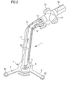
- the receiving device 4 is rotatable in the holding device 1 stored so that the semiconductor wafer located on it 2 together with the receiving device 4 also to turn.
- a handwheel 7 is provided, which is manually by means of a finger of an operator pressed and by means of a drive to be described in more detail the recording device 4 turns.
- the cradle 4 has support arms 8, whose end portions Wear receiving studs 83 for receiving semiconductor wafers 2.
- the receiving device 4 is rotatable in the holding device 1 and has a driving girl 9, around which a fine rope 10 is stretched.
- the fine rope 10 runs within a carrier belonging to the holding device 1 11 in which the receiving device 4 rotatably mounted is.
- pulleys 12 for deflecting the Fine rope 10 arranged by means of which the fine rope 10 both diverted as well as being tense.
- the fine rope 10 wraps around Further, a drive wheel 13, which is in operative connection with the handwheel 7 stands - for example, on a common axis is arranged with this -, thereby moving the fine rope 10 and on the entrainment girl 9, the receiving device. 4 rotates.
- a Control valve 14 for influencing the supply of the gas, which generates the Bernoullie effect and to control the vacuum.
- This control valve 14 can via a push button 15th operated by a finger of a hand of an operator become. The operator can therefore with one hand both turn the semiconductor wafer 2, as well as the supply of the Bernoulligases and the vacuum control.
- the push button 15 with the valve 14 for driving Bernoulli bin and vacuum is designed so that it is in one operation in the Vacuum position engages. This is the hand of the operator free for the operation of the handwheel 7 for correction the position of the flat 2a. When pressed again the vacuum is released, the wafer 2 is released and the push button 15 is back in the starting position.
- the drive shown on wheels 9, 12, 13 and fine rope 10th is only a preferred embodiment and the person skilled in the art If required, the drive can also be designed differently. That's one fluidic (pneumatic or hydraulic) drive as well conceivable as an electric, with the control options maintained by the operator.
- FIG. 3 shows a further exemplary embodiment, in which the geometric arrangement of the Bernoulli jets and the Vacuum holes deviate from the embodiment already shown, without departing from the teachings of the invention.
- This recording device 4 shown in this embodiment with Suction holes 6a in the end portions 6b of the support arms 8 is just another way to provide suction holes 6a.
- This embodiment is feasible, but deviates from the first embodiment, in which suction holes 6a of a vacuum pad 6 in the center 3 of the receiving device 4 are located.
- the embodiment in Figures 1 and 2 corresponds, which in practice also is preferred, the suction holes in the end regions Of course, the support arms 8 omitted.
- the support arms 8 of the rotary receiving device 4 of special meaning, because of this filigree execution
- the semiconductor wafers 2 can be kept the same way as in a fully closed nozzle plate according to the Prior art, however, there covers the nozzle plate to holding semiconductor wafer at least from one side completely from. An optical inspection of the held semiconductor wafer is therefore possible only from one side.
- the invention provides a remedy, because the support arms 8 cover the semiconductor wafer 2 to be held in practice only approximately 20% off, leaving about 80% of the backside of the held semiconductor wafer 2 be subjected to a visual inspection can.
- This filigree design of the holding device 1 has the another significant advantage that their mass is significantly lower is as with a closed nozzle plate according to the state of the art. Handling by the operator This is of course significantly improved, resulting in less waste and shorter handling times.
- FIG Holding device 1 two media connections, a gas connection 16 for outflowing gas to generate the Bernoulli effect and a second, the vacuum port 17, for aspirating Air, so for the generation of vacuum in the cradle 4.
- the device shown is preferably in two parts executed, and that it consists of the actual holding device 1 with the carrier 11 for the receiving device 4th and a handle 18 which are mating.
- a control valve 14 Switch with which the source and quantity of each selected Medium are controlled by means of a push button 15 can.
- This design proves to be advantageous because then different holding devices 1 infected to the handle 18 can be.
- Simultaneously with the mechanical Connection of holding device 1 and handle 18 are the Media connections 16 and 17 for "Bernoulli gas" and "vacuum" each connected to each other.
- FIG. 4 shows a variant of a holding device 1.
- the holding device 1 is similar to that of FIG 1 is formed and carries in the center 3 both nozzle bores 5 and a suction hole 6a.
- the support arms 8 end in spherically shaped circular receiving crests 83 on which the outer region of the semiconductor wafer 2 with the least Pressure is just in a straight line so that flatness is given and a swing is avoided. Because here for the first time a semiconductor wafer 2 is indicated, the flattening is also good F (flater) on the circumference 2a of the semiconductor wafer 2, to their exact alignment when turning the recording device 4 it goes in the invention.
- FIG. 4 shows a variant of the embodiment according to FIG. 4 shown.
- the end portions of the support arms 8 as formed annular portions 84, which is slightly more Edition for the semiconductor wafer 2 offer, resulting in some Cases may be advantageous.
- dashed lines is indicated that the annular sections 84 parts a closed ring 22 may be, in turn Suction openings 23 has.
- This ring 22 stabilizes the Holding device 1, but increases its mass but only slightly and the visual testability of the held surface side the semiconductor wafer 2 also decreases only insignificantly.
Landscapes
- Container, Conveyance, Adherence, Positioning, Of Wafer (AREA)
- Manipulator (AREA)
Abstract
Description
Claims (20)
- Vorrichtung zum Handhaben von Platten, insbesondere zum Handhaben von Halbleiterscheiben mit einer pneumatisch arbeitenden Haltevorrichtung zum hydrodynamischen Halten der Halbleiterscheibe, wobei die Haltevorrichtung über ein Zentrum verfügt, welches zumindest Düsenbohrungen zum Erzeugen eines hydrodynamischen Unterdrucks aufweist, dadurch gekennzeichnet, dass das Zentrum (3)von einer Aufnahmevorrichtung (4) gebildet wird, welche um ihre Mittelachse drehbar in der Haltevorrichtung (1) gelagert ist.
- Vorrichtung nach Anspruch 1, dadurch gekennzeichnet, dass das Zentrum (3) von einer Aufnahmevorrichtung (4) gebildet wird, deren Drehung mittels eines Antriebs (9, 10, 12, 13) erfolgt.
- Vorrichtung nach Anspruch 2, dadurch gekennzeichnet, dass der Antrieb als Seilrollenantrieb (9, 10, 12, 13) ausgebildet ist.
- Vorrichtung nach Anspruch 3, dadurch gekennzeichnet, dass der Seilrollenantrieb (9, 10, 12, 13) durch ein Handrad (7) manuell betätigbar ist.
- Vorrichtung nach Anspruch 2, dadurch gekennzeichnet, dass der Antrieb als fluidischer Antrieb ausgebildet ist.
- Vorrichtung nach Anspruch 5, dadurch gekennzeichnet, dass der fluidische Antrieb von einem Handrad steuerbar ist.
- Vorrichtung nach Anspruch 2, dadurch gekennzeichnet, dass der Antrieb als elektrischer Antrieb ausgebildet ist.
- Vorrichtung nach Anspruch 7, dadurch gekennzeichnet, dass der elektrische Antrieb von einem Handrad steuerbar ist.
- Vorrichtung nach Anspruch 1, dadurch gekennzeichnet, dass die Aufnahmevorrichtung (3) sternförmig nach außen weisende Stützarme (8) aufweist, welche die zu handhabende Halbleiterscheibe (2) zumindest in deren Außenbereich (2a) abstützen, und dass zwischen den sternförmig nach außen weisenden Stützarme (8) Freiflächen vorhanden sind.
- Vorrichtung nach Anspruch 1, dadurch gekennzeichnet, dass die Aufnahmevorrichtung (1) in ihrem Zentrum (3) über eine zusätzliche Bohrung (6a) zum Ansaugen der Halbleiterplatte (2) verfügt.
- Vorrichtung nach Anspruch 9, dadurch gekennzeichnet, dass die Aufnahmevorrichtung (1) an den Endbereichen ihrer Stützarme (8) Aufnahmekuppen (6b, 83, 84) aufweist.
- Vorrichtung nach Anspruch 11, dadurch gekennzeichnet, dass die Aufnahmevorrichtung (1) in den Aufnahmekuppen (6b) Bohrungen (6a) zum Ansaugen der Halbleiterscheibe (2) aufweisen.
- Vorrichtung nach Anspruch 11, dadurch gekennzeichnet, dass die Aufnahmekuppen (6b, 83) der Aufnahmevorrichtung (1) kreisförmig und ballig ausgebildet sind.
- Vorrichtung nach Anspruch 11, dadurch gekennzeichnet, dass die Aufnahmekuppen der Aufnahmevorrichtung (1) durch kreisringförmige Abschnitte (84) gebildet werden, welche eine konvexe Oberflächengestaltung aufweisen.
- Vorrichtung nach Anspruch 9, dadurch gekennzeichnet, dass die Stützarme (8) an ihren Endbereichen (84) mittels eines Ringes (22) miteinander verbunden sind.
- Vorrichtung nach Anspruch 15, dadurch gekennzeichnet, dass im Ring (22) Ansaugöffnungen (23) angeordnet sind.
- Vorrichtung nach Anspruch 9, dadurch gekennzeichnet, dass an den Stützarmen (8) außerhalb der Endbereiche (6b, 83, 84) Stützelemente für die Halbleiterscheibe (2) vorgesehen sind.
- Vorrichtung nach Anspruch 1, dadurch gekennzeichnet, dass die Aufnahmevorrichtung (1)über einen Handgriff (18) verfügt, durch welchen die Anschlüsse(16, 17) für die Gasversorgung und das Vakuum geführt werden.
- Vorrichtung nach Anspruch 1, dadurch gekennzeichnet, dass die Aufnahmevorrichtung (1) und der Handgriff (18) trennbar ausgeführt sind.
- Vorrichtung nach Anspruch 1, dadurch gekennzeichnet, dass ein Druckknopf (15) vorgesehen ist, der Ventil (14) derart beaufschlagt, dass bei einer einmaliger Druckknopfbetätigung die Vakuumposition aktiviert ist, bei nochmaliger Betätigung das Vakuum abgeschaltet und der Druckknopf (15) wieder in der Ausgangsposition ist.
Applications Claiming Priority (2)
| Application Number | Priority Date | Filing Date | Title |
|---|---|---|---|
| DE10304425A DE10304425B3 (de) | 2003-02-04 | 2003-02-04 | Vorrichtung zum Handhaben von Platten |
| DE10304425 | 2003-02-04 |
Publications (3)
| Publication Number | Publication Date |
|---|---|
| EP1445792A2 true EP1445792A2 (de) | 2004-08-11 |
| EP1445792A3 EP1445792A3 (de) | 2005-12-07 |
| EP1445792B1 EP1445792B1 (de) | 2008-09-03 |
Family
ID=32603139
Family Applications (1)
| Application Number | Title | Priority Date | Filing Date |
|---|---|---|---|
| EP04001552A Expired - Lifetime EP1445792B1 (de) | 2003-02-04 | 2004-01-26 | Vorrichtung zum Handhaben von Platten |
Country Status (2)
| Country | Link |
|---|---|
| EP (1) | EP1445792B1 (de) |
| DE (2) | DE10304425B3 (de) |
Cited By (2)
| Publication number | Priority date | Publication date | Assignee | Title |
|---|---|---|---|---|
| DE102012216820A1 (de) * | 2012-09-19 | 2014-03-20 | Robert Bosch Gmbh | Greifeinrichtung für empfindliche Gegenstände und Verwendung einer Greifeinrichtung |
| GB2567041A (en) * | 2017-08-09 | 2019-04-03 | Boeing Co | End effectors carrying plies of limp material for shaping by a mandrel |
Family Cites Families (4)
| Publication number | Priority date | Publication date | Assignee | Title |
|---|---|---|---|---|
| DE19755694C2 (de) * | 1997-12-16 | 2000-05-31 | Sez Semiconduct Equip Zubehoer | Handhabungsvorrichtung für dünne, scheibenförmige Gegenstände |
| JP3610426B2 (ja) * | 1998-06-04 | 2005-01-12 | 東京エレクトロン株式会社 | 基板姿勢制御装置 |
| DE19948572A1 (de) * | 1999-10-08 | 2001-04-19 | Infineon Technologies Ag | Vorrichtung zum Handling von Halbleiterscheiben |
| DE10145049C2 (de) * | 2001-09-13 | 2003-10-16 | Infineon Technologies Ag | Vorrichtung zum Handhaben von Platten |
-
2003
- 2003-02-04 DE DE10304425A patent/DE10304425B3/de not_active Expired - Fee Related
-
2004
- 2004-01-26 DE DE502004007964T patent/DE502004007964D1/de not_active Expired - Lifetime
- 2004-01-26 EP EP04001552A patent/EP1445792B1/de not_active Expired - Lifetime
Cited By (4)
| Publication number | Priority date | Publication date | Assignee | Title |
|---|---|---|---|---|
| DE102012216820A1 (de) * | 2012-09-19 | 2014-03-20 | Robert Bosch Gmbh | Greifeinrichtung für empfindliche Gegenstände und Verwendung einer Greifeinrichtung |
| GB2567041A (en) * | 2017-08-09 | 2019-04-03 | Boeing Co | End effectors carrying plies of limp material for shaping by a mandrel |
| US10369706B2 (en) | 2017-08-09 | 2019-08-06 | The Boeing Company | End effectors carrying plies of limp material for shaping by a mandrel |
| GB2567041B (en) * | 2017-08-09 | 2020-07-08 | Boeing Co | End effectors carrying plies of limp material for shaping by a mandrel |
Also Published As
| Publication number | Publication date |
|---|---|
| DE502004007964D1 (de) | 2008-10-16 |
| EP1445792A3 (de) | 2005-12-07 |
| DE10304425B3 (de) | 2004-08-05 |
| EP1445792B1 (de) | 2008-09-03 |
Similar Documents
| Publication | Publication Date | Title |
|---|---|---|
| DE19755694C2 (de) | Handhabungsvorrichtung für dünne, scheibenförmige Gegenstände | |
| DE60313279T2 (de) | Transportsystem | |
| DE1764891C3 (de) | Verfahren und Einrichtung zum Trennen einer Mehrzahl von plättchen- oder würfelförmigen Gegenständen | |
| EP1091389B1 (de) | Bernoulli- und Vakuum-Kombigreifer | |
| DE60027510T2 (de) | Halbleiterscheibe Poliervorrichtung | |
| DE3041147A1 (de) | Plaettchen-ausrichtvorrichtung | |
| AT502563A1 (de) | Greiferkopf mit vakuumgreifer und steuerventil dazu sowie ein verfahren zum betrieb eines solchen | |
| DE2702261A1 (de) | Verfahren und vorrichtung zum schleifen der kanten eines zerbrechlichen werkstuecks | |
| DE2609754A1 (de) | Halterung fuer das beidseitig beruehrungslose aufnehmen von scheiben | |
| EP0588196A2 (de) | In eine Rohrleitung einführbare Arbeitsvorrichtung | |
| DE102004001350B4 (de) | Fördervorrichtung für ein plattenartiges Werkstück | |
| DE102015217132A1 (de) | Halterungssystem und Beschickungsverfahren für scheibenförmige Objekte | |
| DE102015105259B4 (de) | Werkzeugwechsler für eine Werkzeugmaschine | |
| DE112015000945B4 (de) | Werkstückhaltegerät | |
| EP1445792B1 (de) | Vorrichtung zum Handhaben von Platten | |
| EP2089899A1 (de) | Vorrichtung zum positionieren und/oder anpressen eines flächigen bauteils relativ zu einem substrat und verfahren zum positionieren eines aufnahmewerkzeugs relativ zu einem substrat | |
| CH682085A5 (de) | ||
| EP1294014B1 (de) | Vorrichtung zum Handhaben von Platten | |
| EP4054810A1 (de) | Unterdruckhandhabungsvorrichtung | |
| DE102017103686A1 (de) | Greifvorrichtung mit erhöhter Flexibilität | |
| EP1321969B1 (de) | Verfahren und Vorrichtung zum Handhaben von Halbleiterscheiben | |
| DE4116392C2 (de) | Halterung zur einseitigen Naßätzung von Halbleiterscheiben | |
| EP1291901A2 (de) | Vorrichtung mit einem Greifer zur Handhabung von Platten | |
| DE102021208695A1 (de) | Bearbeitungsvorrichtung | |
| DE69200745T2 (de) | Vorrichtung zum Abschrägen der Kerbe eines Plättchen. |
Legal Events
| Date | Code | Title | Description |
|---|---|---|---|
| PUAI | Public reference made under article 153(3) epc to a published international application that has entered the european phase |
Free format text: ORIGINAL CODE: 0009012 |
|
| AK | Designated contracting states |
Kind code of ref document: A2 Designated state(s): AT BE BG CH CY CZ DE DK EE ES FI FR GB GR HU IE IT LI LU MC NL PT RO SE SI SK TR |
|
| AX | Request for extension of the european patent |
Extension state: AL LT LV MK |
|
| PUAL | Search report despatched |
Free format text: ORIGINAL CODE: 0009013 |
|
| AK | Designated contracting states |
Kind code of ref document: A3 Designated state(s): AT BE BG CH CY CZ DE DK EE ES FI FR GB GR HU IE IT LI LU MC NL PT RO SE SI SK TR |
|
| AX | Request for extension of the european patent |
Extension state: AL LT LV MK |
|
| RIC1 | Information provided on ipc code assigned before grant |
Ipc: 7H 01L 21/68 A |
|
| 17P | Request for examination filed |
Effective date: 20060413 |
|
| AKX | Designation fees paid |
Designated state(s): DE FR GB |
|
| GRAP | Despatch of communication of intention to grant a patent |
Free format text: ORIGINAL CODE: EPIDOSNIGR1 |
|
| GRAS | Grant fee paid |
Free format text: ORIGINAL CODE: EPIDOSNIGR3 |
|
| GRAA | (expected) grant |
Free format text: ORIGINAL CODE: 0009210 |
|
| AK | Designated contracting states |
Kind code of ref document: B1 Designated state(s): DE FR GB |
|
| REG | Reference to a national code |
Ref country code: GB Ref legal event code: FG4D Free format text: NOT ENGLISH |
|
| REF | Corresponds to: |
Ref document number: 502004007964 Country of ref document: DE Date of ref document: 20081016 Kind code of ref document: P |
|
| PLBE | No opposition filed within time limit |
Free format text: ORIGINAL CODE: 0009261 |
|
| STAA | Information on the status of an ep patent application or granted ep patent |
Free format text: STATUS: NO OPPOSITION FILED WITHIN TIME LIMIT |
|
| 26N | No opposition filed |
Effective date: 20090604 |
|
| REG | Reference to a national code |
Ref country code: FR Ref legal event code: PLFP Year of fee payment: 13 |
|
| REG | Reference to a national code |
Ref country code: FR Ref legal event code: PLFP Year of fee payment: 14 |
|
| PGFP | Annual fee paid to national office [announced via postgrant information from national office to epo] |
Ref country code: DE Payment date: 20170316 Year of fee payment: 14 |
|
| REG | Reference to a national code |
Ref country code: FR Ref legal event code: PLFP Year of fee payment: 15 |
|
| PGFP | Annual fee paid to national office [announced via postgrant information from national office to epo] |
Ref country code: GB Payment date: 20180119 Year of fee payment: 15 |
|
| PGFP | Annual fee paid to national office [announced via postgrant information from national office to epo] |
Ref country code: FR Payment date: 20180119 Year of fee payment: 15 |
|
| REG | Reference to a national code |
Ref country code: DE Ref legal event code: R119 Ref document number: 502004007964 Country of ref document: DE |
|
| PG25 | Lapsed in a contracting state [announced via postgrant information from national office to epo] |
Ref country code: DE Free format text: LAPSE BECAUSE OF NON-PAYMENT OF DUE FEES Effective date: 20180801 |
|
| GBPC | Gb: european patent ceased through non-payment of renewal fee |
Effective date: 20190126 |
|
| PG25 | Lapsed in a contracting state [announced via postgrant information from national office to epo] |
Ref country code: FR Free format text: LAPSE BECAUSE OF NON-PAYMENT OF DUE FEES Effective date: 20190131 |
|
| PG25 | Lapsed in a contracting state [announced via postgrant information from national office to epo] |
Ref country code: GB Free format text: LAPSE BECAUSE OF NON-PAYMENT OF DUE FEES Effective date: 20190126 |