EP1445487A2 - Apparatus for assembling swash plate with pistons in a swash plate compressor - Google Patents
Apparatus for assembling swash plate with pistons in a swash plate compressor Download PDFInfo
- Publication number
- EP1445487A2 EP1445487A2 EP04002681A EP04002681A EP1445487A2 EP 1445487 A2 EP1445487 A2 EP 1445487A2 EP 04002681 A EP04002681 A EP 04002681A EP 04002681 A EP04002681 A EP 04002681A EP 1445487 A2 EP1445487 A2 EP 1445487A2
- Authority
- EP
- European Patent Office
- Prior art keywords
- swash plate
- pistons
- piston
- assembling
- compressor according
- Prior art date
- Legal status (The legal status is an assumption and is not a legal conclusion. Google has not performed a legal analysis and makes no representation as to the accuracy of the status listed.)
- Granted
Links
- 238000003780 insertion Methods 0.000 claims description 3
- 230000037431 insertion Effects 0.000 claims description 3
- 238000000034 method Methods 0.000 description 7
- 230000008569 process Effects 0.000 description 5
- 230000004044 response Effects 0.000 description 5
- 239000003507 refrigerant Substances 0.000 description 4
- 230000006835 compression Effects 0.000 description 1
- 238000007906 compression Methods 0.000 description 1
- 238000010276 construction Methods 0.000 description 1
- 238000001816 cooling Methods 0.000 description 1
- 230000008878 coupling Effects 0.000 description 1
- 238000010168 coupling process Methods 0.000 description 1
- 238000005859 coupling reaction Methods 0.000 description 1
- 230000007246 mechanism Effects 0.000 description 1
- 230000004048 modification Effects 0.000 description 1
- 238000012986 modification Methods 0.000 description 1
- 230000002093 peripheral effect Effects 0.000 description 1
- 238000000926 separation method Methods 0.000 description 1
Images


Classifications
-
- F—MECHANICAL ENGINEERING; LIGHTING; HEATING; WEAPONS; BLASTING
- F04—POSITIVE - DISPLACEMENT MACHINES FOR LIQUIDS; PUMPS FOR LIQUIDS OR ELASTIC FLUIDS
- F04B—POSITIVE-DISPLACEMENT MACHINES FOR LIQUIDS; PUMPS
- F04B49/00—Control, e.g. of pump delivery, or pump pressure of, or safety measures for, machines, pumps, or pumping installations, not otherwise provided for, or of interest apart from, groups F04B1/00 - F04B47/00
-
- B—PERFORMING OPERATIONS; TRANSPORTING
- B23—MACHINE TOOLS; METAL-WORKING NOT OTHERWISE PROVIDED FOR
- B23P—METAL-WORKING NOT OTHERWISE PROVIDED FOR; COMBINED OPERATIONS; UNIVERSAL MACHINE TOOLS
- B23P19/00—Machines for simply fitting together or separating metal parts or objects, or metal and non-metal parts, whether or not involving some deformation; Tools or devices therefor so far as not provided for in other classes
- B23P19/04—Machines for simply fitting together or separating metal parts or objects, or metal and non-metal parts, whether or not involving some deformation; Tools or devices therefor so far as not provided for in other classes for assembling or disassembling parts
-
- F—MECHANICAL ENGINEERING; LIGHTING; HEATING; WEAPONS; BLASTING
- F04—POSITIVE - DISPLACEMENT MACHINES FOR LIQUIDS; PUMPS FOR LIQUIDS OR ELASTIC FLUIDS
- F04B—POSITIVE-DISPLACEMENT MACHINES FOR LIQUIDS; PUMPS
- F04B27/00—Multi-cylinder pumps specially adapted for elastic fluids and characterised by number or arrangement of cylinders
- F04B27/08—Multi-cylinder pumps specially adapted for elastic fluids and characterised by number or arrangement of cylinders having cylinders coaxial with, or parallel or inclined to, main shaft axis
- F04B27/0873—Component parts, e.g. sealings; Manufacturing or assembly thereof
- F04B27/0878—Pistons
-
- F—MECHANICAL ENGINEERING; LIGHTING; HEATING; WEAPONS; BLASTING
- F04—POSITIVE - DISPLACEMENT MACHINES FOR LIQUIDS; PUMPS FOR LIQUIDS OR ELASTIC FLUIDS
- F04B—POSITIVE-DISPLACEMENT MACHINES FOR LIQUIDS; PUMPS
- F04B27/00—Multi-cylinder pumps specially adapted for elastic fluids and characterised by number or arrangement of cylinders
- F04B27/08—Multi-cylinder pumps specially adapted for elastic fluids and characterised by number or arrangement of cylinders having cylinders coaxial with, or parallel or inclined to, main shaft axis
- F04B27/10—Multi-cylinder pumps specially adapted for elastic fluids and characterised by number or arrangement of cylinders having cylinders coaxial with, or parallel or inclined to, main shaft axis having stationary cylinders
- F04B27/1036—Component parts, details, e.g. sealings, lubrication
-
- F—MECHANICAL ENGINEERING; LIGHTING; HEATING; WEAPONS; BLASTING
- F04—POSITIVE - DISPLACEMENT MACHINES FOR LIQUIDS; PUMPS FOR LIQUIDS OR ELASTIC FLUIDS
- F04B—POSITIVE-DISPLACEMENT MACHINES FOR LIQUIDS; PUMPS
- F04B39/00—Component parts, details, or accessories, of pumps or pumping systems specially adapted for elastic fluids, not otherwise provided for in, or of interest apart from, groups F04B25/00 - F04B37/00
- F04B39/14—Provisions for readily assembling or disassembling
-
- Y—GENERAL TAGGING OF NEW TECHNOLOGICAL DEVELOPMENTS; GENERAL TAGGING OF CROSS-SECTIONAL TECHNOLOGIES SPANNING OVER SEVERAL SECTIONS OF THE IPC; TECHNICAL SUBJECTS COVERED BY FORMER USPC CROSS-REFERENCE ART COLLECTIONS [XRACs] AND DIGESTS
- Y10—TECHNICAL SUBJECTS COVERED BY FORMER USPC
- Y10T—TECHNICAL SUBJECTS COVERED BY FORMER US CLASSIFICATION
- Y10T29/00—Metal working
- Y10T29/49—Method of mechanical manufacture
- Y10T29/49229—Prime mover or fluid pump making
- Y10T29/49236—Fluid pump or compressor making
-
- Y—GENERAL TAGGING OF NEW TECHNOLOGICAL DEVELOPMENTS; GENERAL TAGGING OF CROSS-SECTIONAL TECHNOLOGIES SPANNING OVER SEVERAL SECTIONS OF THE IPC; TECHNICAL SUBJECTS COVERED BY FORMER USPC CROSS-REFERENCE ART COLLECTIONS [XRACs] AND DIGESTS
- Y10—TECHNICAL SUBJECTS COVERED BY FORMER USPC
- Y10T—TECHNICAL SUBJECTS COVERED BY FORMER US CLASSIFICATION
- Y10T29/00—Metal working
- Y10T29/53—Means to assemble or disassemble
- Y10T29/53313—Means to interrelatedly feed plural work parts from plural sources without manual intervention
- Y10T29/53374—Means to interrelatedly feed plural work parts from plural sources without manual intervention including turret-type conveyor
-
- Y—GENERAL TAGGING OF NEW TECHNOLOGICAL DEVELOPMENTS; GENERAL TAGGING OF CROSS-SECTIONAL TECHNOLOGIES SPANNING OVER SEVERAL SECTIONS OF THE IPC; TECHNICAL SUBJECTS COVERED BY FORMER USPC CROSS-REFERENCE ART COLLECTIONS [XRACs] AND DIGESTS
- Y10—TECHNICAL SUBJECTS COVERED BY FORMER USPC
- Y10T—TECHNICAL SUBJECTS COVERED BY FORMER US CLASSIFICATION
- Y10T29/00—Metal working
- Y10T29/53—Means to assemble or disassemble
- Y10T29/53539—Means to assemble or disassemble including work conveyor
Definitions
- the present invention relates to an apparatus for assembling a swash plate with pistons in a swash plate compressor.
- the apparatus for assembling a swash plate with pistons in a swash plate compressor of the present invention can automatically assemble the swash plate with double or single head pistons and shoes thereby improving workability and productivity.
- a compressor in a vehicle cooling system selectively receives power from an engine through a vehicle pulley in response to engagement/disengagment of an electronic clutch in order to suck in refrigerant which is heat exchanged in an evaporator, compress the refrigerant with a piston and discharge the compressed refrigerant to a condenser.
- Compressors are divided into various forms such as reciprocating and rotary compressors according to their compression policy and structure. Reciprocating compressors are further divided into crank, swash plate and wobble plate compressors. Rotary compressors are further divided into vane rotary and scroll compressors.
- the swash plate compressor can be generally divided into fixed and variable capacity compressors, in which the fixed capacity compressor uses double head pistons, and the variable capacity compressor uses single head pistons.
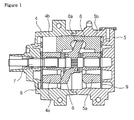
- a fixed capacity compressor includes a front housing 4 having a front cylinder 4a integrally formed within the front housing 4, a rear housing 5 coupled in face-contact with the front housing 4 and having a rear cylinder 5a integrally formed within the rear housing 5, a plurality of double head pistons 6 arranged in a linearly reciprocating fashion in bores 4b of the front cylinder 4a and bores 5b of the rear cylinder 5a, a drive shaft 7 arranged in a rotatable fashion through central portions of the front and rear cylinders 4a and 5a of the front and rear housings 4 and 5, a swash plate 8 mounted at an inclination on the drive shaft 7 so that it is turned in response to rotation of the drive shaft 7 to move the pistons 6 forward and backward and front and rear valve switches 9 arranged respectively between the front cylinder 4a and the front housing 4 and between the rear cylinder 5a and the rear housing 5.
- the reference numeral 6a designates a shoe.
- a variable capacity swash plate compressor includes a cylinder block 10, a front housing 20, a rear housing 30, single head pistons 40, a drive shaft 50, a rotor 60, a swash plate 70, a valve unit 80 and a control valve 90.
- the cylinder block 10 has a central bore 11 and a plurality of cylinder bores 12 extended through the cylinder block 10.
- the cylinder bores 12 are formed radially around the central bore 11 at a uniform interval.
- the front and rear housings 20 and 30 are arranged respectively in front and rear ends of the cylinder block 10 so that three components of the front and rear housings 20 and 30 and the cylinder bock 10 are coupled into one part via an elongate bolt 21.
- Each of the single head pistons 40 is slidably arranged within each of the cylinder bores 12, and has a body 41 and a bridge portion 42.
- the drive shaft 50 is extended rotatably through a central portion of a front wall of the front housing 20 and a crank chamber 22 formed within the front housing 20 so that a rear end of the drive shaft 50 being supported rotatably to a central portion of the cylinder block 10.
- the cylinder block 10 together with the front housing 20 defines an internal space, which is in a hermetic state to be used as the crank chamber 20.
- the rotor 60 is mounted around the drive shaft 50 in a front portion of the crank chamber 22 to be turned in response to rotation of the drive shaft 50.
- the swash plate 70 is installed in a central portion of the crank chamber 22 in such a fashion that it can be adjusted in inclination around the drive shaft 50.
- the swash plate 70 and the rotor 60 are connected via a hinge mechanism to be turned together with the same.
- a support arm 61 is projected from a surface portion of the rotor 60 outward along the drive shaft 50, and a swash plate arm 71 is projected from a surface portion of the swash plate 70 toward the support arm 61 of the rotor 60.
- the support arm 61 is connected with the swash plate arm 71 via a pin 62.
- a portion of the outer periphery of the swash plate 70 is rotatably inserted into the bridge portion 42 of the single head piston 40.
- the swash plate 70 can be turned not only along with the rotor 60 at rotation by the drive shaft 50 but also forward and backward around the pin 62 in response to the internal pressure of the crank chamber 22 so that the inclination of the swash plate 70 can be adjusted.
- valve unit 80 is arranged between the cylinder block 10 and the rear housing 30 to regulate intake and discharge of refrigerant.
- a prior art for assembling the double head piston 6 or the single head piston 40 to the swash plate 8 or 70 as shown in FIGS. 1 and 2 is disclosed in Korean Patent Application Publication No.1999-0064088.
- both heads of the pistons assembled to the swash plate are supported by two piston supports or piston supports of the two support heads. Then, there is also a problem that the apparatus is complicated.
- the present invention has been made to solve the foregoing problems.
- an apparatus for assembling a swash plate with pistons in a swash plate compressor wherein each of the pistons includes a swash plate-receiving section for receiving a pair of opposed shoes therein and having an insert groove for receiving the swash plate mounted on a rotational shaft and a piston body to be inserted into a cylinder bore of a cylinder block so that the swash plate is inserted into the insert grooves of the pistons
- the apparatus comprising: a base plate; piston-loading means for loading the pistons to be lined up in a longitudinal direction; piston-shifting means arranged slidably on the base plate for shifting the pistons loaded by the piston-loading means in order; and rotating means for rotating the swash plate so that the pistons shifted by the piston-shifting means are assembled to the swash plate.
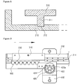
- FIGS. 1 and 2 are sectional views illustrating internal structures of conventional swash plate compressors
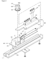
- FIG. 3 is an exploded perspective view of an assembling apparatus of the present invention.
- FIG. 4 is a partial perspective view illustrating a pinion and a rack meshed with each other according to the present invention
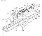
- FIG. 5 is an assembled perspective view of the assembling apparatus of the present invention.
- FIG. 6 is a partial sectional view illustrating the pinion and the rack meshed with each other according to the present invention.
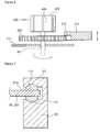
- FIG. 7 is a sectional view illustrating a stationary guide member introduced into an insert groove of a piston according to the present invention.
- FIG. 8 is a sectional view illustrating a transport plate coupled with a base plate according to the present invention.
- FIG. 9 is a plan view of FIG. 5;
- FIGS. 10 to 12 illustrate a process of assembling pistons to a swash plate according to the present invention.
- FIG. 13 illustrates an alternative embodiment of the present invention.
- FIG. 3 is an exploded perspective view of an assembling apparatus of the present invention
- FIG. 4 is a partial perspective view illustrating a pinion and a rack meshed with each other according to the present invention
- FIG. 5 is an assembled perspective view of the assembling apparatus of the present invention
- FIG. 6 is a partial sectional view illustrating the pinion and the rack meshed with each other according to the present invention
- FIG. 7 is a sectional view illustrating a stationary guide member introduced into an insert groove of a piston according to the present invention
- FIG. 8 is a sectional view illustrating a transport plate coupled with a base plate according to the present invention
- FIG. 9 is a plan view of FIG. 5
- FIGS. 10 to 12 illustrate a process of assembling pistons to a swash plate according to the present invention
- FIG. 13 illustrates an alternative embodiment of the present invention.
- the present invention relates to an apparatus for assembling a swash plate 130 with pistons 100 in a swash plate compressor, in which each of the pistons 100 includes a swash plate-receiving section 101 for receiving a pair of opposed shoes 110 and 111 therein and having an insert groove 101a for receiving the swash plate 130 mounted on a rotational shaft 120 and a piston body 102 to be inserted into a cylinder bore of a cylinder block so that the swash plate 130 is inserted into the insert grooves 101a of the pistons 100.
- the assembling apparatus of the present invention includes piston-loading means 200 for loading the pistons 100 to be lined up in a vertically erected position, piston-shifting means 300 for shifting the pistons 100 loaded by the piston-loading means 200 in order and rotating means 400 for rotating the swash plate 130 so that the pistons 100 shifted by the piston-shifting means 300 are assembled to the swash plate 130.
- the piston-loading means 200 includes a base plate 210, a stationary guide member 220 and a piston-loading member 230.
- the base plate 210 is spaced to a predetermined height from a working table.
- the stationary guide member 220 is fixed to the base plate 210 to guide the pistons 100 in a line, in which the stationary guide member 220 is fixedly arranged in the base plate 210 for guiding the pistons 100 to be lined up, and inserted into the insert grooves 101a of the pistons 100 with the shoes 110 and 111 contained in the insert grooves 101a in such a fashion that its top and underside are contacted with the shoes 110 and 111.
- the stationary guide member 200 is placed in a horizontal position, and the pistons 100 are loaded in vertical positions.
- the piston-loading member 230 spaces the pistons 100 to a predetermined gap.
- the piston-loading member 230 has a number of loading grooves 231 into which bodies 102 of the pistons 100 are partially inserted.
- the piston-shifting means 300 has a transport plate 310 which is arranged slidable with respect to the base plate 210, and supports bottoms of the bodies 102 of the pistons 100 guided by the stationary guide member 220.
- a guide groove 211 is formed longitudinally in an upper surface of the base plate 210 and an insert portion 311 is formed in the bottom of the transport plate 310 so that it can be inserted into and slid along the guide groove 211.
- piston-loading member 230 is detachably coupled with the transport plate 310 via fastening bolts 233.
- the rotating means 400 includes an auxiliary plate 410 and a movable guide member 420.
- the auxiliary plate 410 is spaced to a predetermined height from the working table.
- a lower end of the rotational shaft 120 is fixedly inserted in part into an upper central portion of the movable guide member 420, and a shaft portion 421 is projected from a lower central portion of the movable guide member 420 and rotatably extended through the auxiliary plate 410.
- the movable guide member 420 cooperates with the piston-shifting means 300 to rotate the swash plate 130 together with the rotational shaft 120.
- the movable guide member 420 receives the bodies 102 of the pistons 100 at least in part to guide the same.
- the movable guide member 420 has a plurality of piston-receiving grooves 424 in the outer periphery thereof for receiving the bodies 102 of the pistons 100 in part.
- the reference numeral 420a designates an insert hole into which the rotational shaft 120 of the swash plate 130 is inserted.
- a block 430 which is opened in an upper end and a lateral portion for allowing the pistons 100 to be introduced.
- the block 430 also has a space 431 for surrounding the movable guide member 420.
- a pinion 422 is formed around the shaft portion 421 of the movable guide member 420, and a rack 212 is formed in the transport plate 310 to mesh with the pinion 422.
- the pistons 100 illustrated so far are single head pistons used in a variable capacity compressor.
- a predetermined number of the pistons 110 for example seven pistons 110 in the embodiment of the present invention, as shown in FIGS. 5 and 9, are supplied to the stationary guide member 220 so that the shoes 110 are 111 are grasped by upper and lower surfaces of the stationary guide member 220 as shown in FIG. 7, in which the stationary guide member 220 is introduced into the insert groove 101a while the upper and lower surfaces of the stationary guide member 220 are contacted with the shoes 110 and 111, and then the process of the present invention is carried out.
- the assembling apparatus Since the pistons 100 are loaded on the stationary guide member 220 by grasping the shoes 110 and 111 of the pistons 100 with the upper and lower surfaces of the stationary member 220, the assembling apparatus does not need any additional pressing member for ensuring a space for insertion of a swash plate prior to assembling the pistons with the swash plate. This simplifies the structure of the assembling apparatus of the present invention.
- the first one of the pistons 100 is coupled with the swash plate 130 in response to rotation of the movable guide member 420.
- the assembly apparatus of the present invention does not need any additional means such as a center stand having two separate center bolts or two center pins which are used in the prior art to fix the swash plate at a specific angle. This can simplify the structure of the assembling apparatus of the present invention.
- the assembling apparatus of the present invention can prevent or reduce probability that the pistons are erroneously assembled.
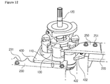
- the stationary guide member 220 may further include an anti-release member 432 provided under an end portion thereof as shown in FIG. 12.
- the stationary guide member 220 serves to guide the pistons 100 as well as prevent release of the pistons 100 from the swash plate 130.
- a separating member 250 which is formed separate from the guide member 220 and coupled with the same via additional fastening bolts 251.
- the separating member 250 is provided collinear with the swash plate 130, which is placed on the movable guide member 420, in order to guide the pistons 100 and the shoes 110 and 111 to be stably coupled with the swash plate 130.
- a plurality of fixing pins 423 are formed in the top of the movable guide member 420 and pin-receiving grooves 131 are formed in the bottom of the swash plate 130 to receive the fixing pins 423 so that the swash plate 130 maintain a certain direction.
- the present invention allows the double or single head pistons and the shoes to be assembled to the swash plate thereby improving workability and productivity.
- the present invention can rapidly and readily assemble a suitable number of the pistons and the shoes to the swash plate by contacting the upper and lower surfaces of the stationary guide member with the shoes, thereby simplifying the assembling apparatus.
- the present invention has advantages that the pistons can be assembled to the swash plate without supporting both ends and productivity can be improved.
- the pistons can be easily assembled to the swash plate since it is not necessary to set the swash plate at a specific angle during assembling operation.
Abstract
Description
- The present invention relates to an apparatus for assembling a swash plate with pistons in a swash plate compressor. In particular, the apparatus for assembling a swash plate with pistons in a swash plate compressor of the present invention can automatically assemble the swash plate with double or single head pistons and shoes thereby improving workability and productivity.
- In general, a compressor in a vehicle cooling system selectively receives power from an engine through a vehicle pulley in response to engagement/disengagment of an electronic clutch in order to suck in refrigerant which is heat exchanged in an evaporator, compress the refrigerant with a piston and discharge the compressed refrigerant to a condenser.
- Compressors are divided into various forms such as reciprocating and rotary compressors according to their compression policy and structure. Reciprocating compressors are further divided into crank, swash plate and wobble plate compressors. Rotary compressors are further divided into vane rotary and scroll compressors.
- In the above various compressors, the swash plate compressor can be generally divided into fixed and variable capacity compressors, in which the fixed capacity compressor uses double head pistons, and the variable capacity compressor uses single head pistons.
- Hereinafter the fixed capacity compressor and the variable capacity compressor will be described briefly with reference to FIGS. 1 and 2.
- First, as shown in FIG. 1, a fixed capacity compressor includes a
front housing 4 having afront cylinder 4a integrally formed within thefront housing 4, arear housing 5 coupled in face-contact with thefront housing 4 and having arear cylinder 5a integrally formed within therear housing 5, a plurality ofdouble head pistons 6 arranged in a linearly reciprocating fashion inbores 4b of thefront cylinder 4a and bores 5b of therear cylinder 5a, adrive shaft 7 arranged in a rotatable fashion through central portions of the front andrear cylinders rear housings swash plate 8 mounted at an inclination on thedrive shaft 7 so that it is turned in response to rotation of thedrive shaft 7 to move thepistons 6 forward and backward and front andrear valve switches 9 arranged respectively between thefront cylinder 4a and thefront housing 4 and between therear cylinder 5a and therear housing 5. - The
reference numeral 6a designates a shoe. - Then, as shown in FIG. 2, a variable capacity swash plate compressor includes a
cylinder block 10, afront housing 20, arear housing 30,single head pistons 40, adrive shaft 50, arotor 60, aswash plate 70, avalve unit 80 and acontrol valve 90. - The
cylinder block 10 has acentral bore 11 and a plurality ofcylinder bores 12 extended through thecylinder block 10. Thecylinder bores 12 are formed radially around thecentral bore 11 at a uniform interval. - The front and
rear housings cylinder block 10 so that three components of the front andrear housings cylinder bock 10 are coupled into one part via anelongate bolt 21. - Each of the
single head pistons 40 is slidably arranged within each of thecylinder bores 12, and has abody 41 and abridge portion 42. - The
drive shaft 50 is extended rotatably through a central portion of a front wall of thefront housing 20 and a crank chamber 22 formed within thefront housing 20 so that a rear end of thedrive shaft 50 being supported rotatably to a central portion of thecylinder block 10. - The
cylinder block 10 together with thefront housing 20 defines an internal space, which is in a hermetic state to be used as thecrank chamber 20. - The
rotor 60 is mounted around thedrive shaft 50 in a front portion of the crank chamber 22 to be turned in response to rotation of thedrive shaft 50. - The
swash plate 70 is installed in a central portion of the crank chamber 22 in such a fashion that it can be adjusted in inclination around thedrive shaft 50. In more detail, theswash plate 70 and therotor 60 are connected via a hinge mechanism to be turned together with the same. - That is, a
support arm 61 is projected from a surface portion of therotor 60 outward along thedrive shaft 50, and aswash plate arm 71 is projected from a surface portion of theswash plate 70 toward thesupport arm 61 of therotor 60. Thesupport arm 61 is connected with theswash plate arm 71 via a pin 62. - A portion of the outer periphery of the
swash plate 70 is rotatably inserted into thebridge portion 42 of thesingle head piston 40. - As connected with the
rotor 60 and thebridge portion 42 of thesingle head piston 40, theswash plate 70 can be turned not only along with therotor 60 at rotation by thedrive shaft 50 but also forward and backward around the pin 62 in response to the internal pressure of the crank chamber 22 so that the inclination of theswash plate 70 can be adjusted. - In the meantime, the
valve unit 80 is arranged between thecylinder block 10 and therear housing 30 to regulate intake and discharge of refrigerant. - A prior art for assembling the
double head piston 6 or thesingle head piston 40 to theswash plate - According to the prior art, when the pair of shoes are mounted on notch of the pistons with spherical surfaces of the shoes being laid toward bottoms of the notch, and a slide table loaded with the pistons is moved toward the swash plate, the spherical surfaces of the shoes are vertically rotated through the right and left outside the notch while flat surfaces of the shoes are contacted with both sides of the periphery of the swash plate so that the pistons together with the shoes are mounted on the swash plate. As a result, there is a problem that an additional pressing member is used to ensure a space so that a peripheral portion of the swash plate is inserted between the shoes before the pistons are assembled to the swash plate.
- Although the assembling process of the prior art is completed when the spherical surfaces of the shoes are vertically rotated through the right and left outside the notch and at the same time flat surfaces of the shoes are contacted with both sides of the periphery of the swash plate, there is a problem that the shoes are frequently shifted in positions during being pressed by the pressing member and erroneously assembled to the swash plate thereby lowering assembly rate.
- Since the prior art tightens center bolts installed in a center stand to fix both ends of a rotational shaft or uses center pins provided in a support head in order to fix the swash plate at a predetermined angle, there is another problem that an apparatus is complicated.
- Furthermore, according to the prior art, both heads of the pistons assembled to the swash plate are supported by two piston supports or piston supports of the two support heads. Then, there is also a problem that the apparatus is complicated.
- The present invention has been made to solve the foregoing problems.
- It is therefore an object of the present invention to provide an apparatus for assembling a swash plate with pistons in a swash plate compressor capable of automatically assembling double or single head pistons and shoes to the swash plate in order to improve workability and productivity.
- According to an aspect of the present invention, there is provided an apparatus for assembling a swash plate with pistons in a swash plate compressor, wherein each of the pistons includes a swash plate-receiving section for receiving a pair of opposed shoes therein and having an insert groove for receiving the swash plate mounted on a rotational shaft and a piston body to be inserted into a cylinder bore of a cylinder block so that the swash plate is inserted into the insert grooves of the pistons, the apparatus comprising: a base plate; piston-loading means for loading the pistons to be lined up in a longitudinal direction; piston-shifting means arranged slidably on the base plate for shifting the pistons loaded by the piston-loading means in order; and rotating means for rotating the swash plate so that the pistons shifted by the piston-shifting means are assembled to the swash plate.
- The above and other objects, features and other advantages of the present invention will be more clearly understood from the following detailed description taken in conjunction with the accompanying drawings, in which:
- FIGS. 1 and 2 are sectional views illustrating internal structures of conventional swash plate compressors;
- FIG. 3 is an exploded perspective view of an assembling apparatus of the present invention;
- FIG. 4 is a partial perspective view illustrating a pinion and a rack meshed with each other according to the present invention;
- FIG. 5 is an assembled perspective view of the assembling apparatus of the present invention;
- FIG. 6 is a partial sectional view illustrating the pinion and the rack meshed with each other according to the present invention;
- FIG. 7 is a sectional view illustrating a stationary guide member introduced into an insert groove of a piston according to the present invention;
- FIG. 8 is a sectional view illustrating a transport plate coupled with a base plate according to the present invention;
- FIG. 9 is a plan view of FIG. 5;
- FIGS. 10 to 12 illustrate a process of assembling pistons to a swash plate according to the present invention; and
- FIG. 13 illustrates an alternative embodiment of the present invention.
- Hereinafter a preferred embodiment of an apparatus for assembling a swash plate with pistons in a swash plate compressor will be described with reference to the accompanying drawings.
- FIG. 3 is an exploded perspective view of an assembling apparatus of the present invention, FIG. 4 is a partial perspective view illustrating a pinion and a rack meshed with each other according to the present invention, FIG. 5 is an assembled perspective view of the assembling apparatus of the present invention, FIG. 6 is a partial sectional view illustrating the pinion and the rack meshed with each other according to the present invention, FIG. 7 is a sectional view illustrating a stationary guide member introduced into an insert groove of a piston according to the present invention, FIG. 8 is a sectional view illustrating a transport plate coupled with a base plate according to the present invention, FIG. 9 is a plan view of FIG. 5, FIGS. 10 to 12 illustrate a process of assembling pistons to a swash plate according to the present invention, and FIG. 13 illustrates an alternative embodiment of the present invention.
- The present invention relates to an apparatus for assembling a
swash plate 130 withpistons 100 in a swash plate compressor, in which each of thepistons 100 includes a swash plate-receivingsection 101 for receiving a pair ofopposed shoes insert groove 101a for receiving theswash plate 130 mounted on arotational shaft 120 and apiston body 102 to be inserted into a cylinder bore of a cylinder block so that theswash plate 130 is inserted into theinsert grooves 101a of thepistons 100. The assembling apparatus of the present invention includes piston-loading means 200 for loading thepistons 100 to be lined up in a vertically erected position, piston-shifting means 300 for shifting thepistons 100 loaded by the piston-loading means 200 in order and rotatingmeans 400 for rotating theswash plate 130 so that thepistons 100 shifted by the piston-shifting means 300 are assembled to theswash plate 130. - The piston-loading means 200 includes a
base plate 210, astationary guide member 220 and a piston-loading member 230. - The
base plate 210 is spaced to a predetermined height from a working table. - The
stationary guide member 220 is fixed to thebase plate 210 to guide thepistons 100 in a line, in which thestationary guide member 220 is fixedly arranged in thebase plate 210 for guiding thepistons 100 to be lined up, and inserted into theinsert grooves 101a of thepistons 100 with theshoes insert grooves 101a in such a fashion that its top and underside are contacted with theshoes - The
stationary guide member 200 is placed in a horizontal position, and thepistons 100 are loaded in vertical positions. - When loading the
pistons 100 guided by thestationary guide member 220, the piston-loading member 230 spaces thepistons 100 to a predetermined gap. - The piston-
loading member 230 has a number ofloading grooves 231 into whichbodies 102 of thepistons 100 are partially inserted. - In the meantime, the piston-shifting means 300 has a
transport plate 310 which is arranged slidable with respect to thebase plate 210, and supports bottoms of thebodies 102 of thepistons 100 guided by thestationary guide member 220. - Describing a coupling construction of the piston-shifting means 300 and the
base plate 210, aguide groove 211 is formed longitudinally in an upper surface of thebase plate 210 and aninsert portion 311 is formed in the bottom of thetransport plate 310 so that it can be inserted into and slid along theguide groove 211. - Herein, the piston-
loading member 230 is detachably coupled with thetransport plate 310 viafastening bolts 233. - In the meantime, the rotating
means 400 includes anauxiliary plate 410 and amovable guide member 420. - The
auxiliary plate 410 is spaced to a predetermined height from the working table. - A lower end of the
rotational shaft 120 is fixedly inserted in part into an upper central portion of themovable guide member 420, and ashaft portion 421 is projected from a lower central portion of themovable guide member 420 and rotatably extended through theauxiliary plate 410. Themovable guide member 420 cooperates with the piston-shifting means 300 to rotate theswash plate 130 together with therotational shaft 120. When theswash plate 130 is inserted into theinsertion grooves 101a of thepistons 100, themovable guide member 420 receives thebodies 102 of thepistons 100 at least in part to guide the same. - The
movable guide member 420 has a plurality of piston-receivinggrooves 424 in the outer periphery thereof for receiving thebodies 102 of thepistons 100 in part. - The
reference numeral 420a designates an insert hole into which therotational shaft 120 of theswash plate 130 is inserted. - On the top of the
auxiliary plate 410, there is also provided ablock 430 which is opened in an upper end and a lateral portion for allowing thepistons 100 to be introduced. Theblock 430 also has aspace 431 for surrounding themovable guide member 420. - A
pinion 422 is formed around theshaft portion 421 of themovable guide member 420, and arack 212 is formed in thetransport plate 310 to mesh with thepinion 422. - The
pistons 100 illustrated so far are single head pistons used in a variable capacity compressor. - Hereinafter a process of assembling a swash plate with pistons using the assembling apparatus of the present invention will be described.
- First, a predetermined number of the
pistons 110 for example sevenpistons 110 in the embodiment of the present invention, as shown in FIGS. 5 and 9, are supplied to thestationary guide member 220 so that theshoes 110 are 111 are grasped by upper and lower surfaces of thestationary guide member 220 as shown in FIG. 7, in which thestationary guide member 220 is introduced into theinsert groove 101a while the upper and lower surfaces of thestationary guide member 220 are contacted with theshoes - Since the
pistons 100 are loaded on thestationary guide member 220 by grasping theshoes pistons 100 with the upper and lower surfaces of thestationary member 220, the assembling apparatus does not need any additional pressing member for ensuring a space for insertion of a swash plate prior to assembling the pistons with the swash plate. This simplifies the structure of the assembling apparatus of the present invention. - After the above procedure, when an external force is applied to the
transport plate 310 along an arrow, thetransport plate 310 is slid with respect to thebase plate 210 shifting the piston-loading member 230 along with thepistons 100 as shown in FIG. 10. - When the
transport plate 310 is moved, themovable guide member 420 is rotated as shown in FIG. 4. - That is, as shown in FIG. 10, the first one of the
pistons 100 is coupled with theswash plate 130 in response to rotation of themovable guide member 420. - Continuing the above procedure, two or three of the
pistons 100 are coupled with theswash plate 130 as shown in FIG. 11, and all of the sevenpistons 100 are finally coupled with theswash plate 130 as shown in FIG. 12. - As described above, as the
swash plate 130 is positioned horizontal by inserting only the lower end of therotational shaft 120 into the upper surface of themovable guide member 420, the assembly apparatus of the present invention does not need any additional means such as a center stand having two separate center bolts or two center pins which are used in the prior art to fix the swash plate at a specific angle. This can simplify the structure of the assembling apparatus of the present invention. - Also, because the
pistons 100 together with theshoes swash plate 130 via thestationary guide member 220 collinear with theswash plate 130, the assembling apparatus of the present invention can prevent or reduce probability that the pistons are erroneously assembled. - Then, the
rotational shaft 120 coupled with theswash plate 130, which is loaded with all of the sevenpistons 100, is drawn from themovable guide member 420 by an operator, so that thepistons 100 are inserted into cylinder bores of a cylinder block. - In the meantime, the
stationary guide member 220 may further include ananti-release member 432 provided under an end portion thereof as shown in FIG. 12. When thepistons 100 assembled to theswash plate 130 are passed through the opened portion of theblock 430, thestationary guide member 220 serves to guide thepistons 100 as well as prevent release of thepistons 100 from theswash plate 130. - Also as shown in FIG. 12, at an end portion of the
stationary guide member 220, there is also provided a separatingmember 250 which is formed separate from theguide member 220 and coupled with the same viaadditional fastening bolts 251. When theswash plate 130 assembled with all of thepistons 100 is separated from themovable guide member 420, the separatingmember 250 is detached from thestationary guide member 220 so that the separatingmember 250 may not prevent separation of theswash plate 130. - The separating
member 250 is provided collinear with theswash plate 130, which is placed on themovable guide member 420, in order to guide thepistons 100 and theshoes swash plate 130. - Further, as shown in FIG. 13, a plurality of fixing
pins 423 are formed in the top of themovable guide member 420 and pin-receivinggrooves 131 are formed in the bottom of theswash plate 130 to receive the fixing pins 423 so that theswash plate 130 maintain a certain direction. - While the present invention has been described on the basis that the pistons are supplied vertically to be assembled, it is to be understood that the afore-described apparatus can be simply modified in design so that the pistons can be supplied horizontally to be assembled.
- Also, while the present invention has been illustrated about the single head pistons used in the variable capacity compressor, it is apparent that the present invention can be applied to the double head compressor used in the fixed capacity compressor.
- As set forth above, the present invention allows the double or single head pistons and the shoes to be assembled to the swash plate thereby improving workability and productivity.
- Also, the present invention can rapidly and readily assemble a suitable number of the pistons and the shoes to the swash plate by contacting the upper and lower surfaces of the stationary guide member with the shoes, thereby simplifying the assembling apparatus.
- Further, the present invention has advantages that the pistons can be assembled to the swash plate without supporting both ends and productivity can be improved.
- There are further advantages of excellent applicability and universality since the assembling apparatus of the present invention can be modified easily according to the modification in design of the pistons or the swash plate or the compressor type.
- Moreover, according to the present invention, the pistons can be easily assembled to the swash plate since it is not necessary to set the swash plate at a specific angle during assembling operation.
Claims (15)
- An apparatus for assembling a swash plate (130) with pistons (100) in a swash plate compressor, wherein each of the pistons (100) includes a swash plate-receiving section (101) for receiving a pair of opposed shoes (110, 111) therein and having an insert groove (101a) for receiving the swash plate (130) mounted on a rotational shaft (120) and a piston body (102) to be inserted into a cylinder bore of a cylinder block so that the swash plate (130) is inserted into the insert grooves (101a) of the pistons (100), the apparatus characterized by:a base plate (210);a piston-loading means (200) for loading the pistons (100) to be lined up in a longitudinal direction;a piston-shifting means (300) arranged slidably on the base plate (210) for shifting position of the pistons (100) loaded by the piston-loading means (200) in order; anda rotating means (400) for rotating the swash plate (130) so that the pistons (100) shifted by the piston-shifting means (300) are assembled to the swash plate (130).
- The apparatus for assembling a swash plate (130) with pistons (100) in a swash plate compressor according to claim 1, wherein the piston-loading means (200) comprising:a stationary guide member (220) fixedly arranged in the base plate (210) for guiding the pistons (100) to be lined up, the stationary guide member (220) being inserted into the insert grooves (101a) of the pistons (100) with the shoes (110, 111) accomodated in the insert grooves (101a) in such a fashion that its top and bottom are contacted with the shoes (110, 111); anda piston-loading member (230) for loading the pistons (100) guided by the stationary guide member (220) to a predetermined spaced gap.
- The apparatus for assembling a swash plate (130) with pistons (100) in a swash plate compressor according to claim 2, wherein the piston-loading member (230) has a plurality of loading grooves (231) into which bodies (102) of the pistons (100) are inserted partially.
- The apparatus for assembling a swash plate (130) with pistons (100) in a swash plate compressor according to claim 1, wherein the piston-shifting means (300) is a transport plate (310) which is arranged slidable with respect to the base plate (210), and supports undersides of the bodies (102) of the pistons (100).
- The apparatus for assembling a swash plate (130) with pistons (100) in a swash plate compressor according to claim 2, wherein the piston-shifting means (300) is a transport plate (310) which is arranged slidable with respect to the base plate (210), and supports undersides of the bodies (102) of the pistons (100).
- The apparatus for assembling a swash plate (130) with pistons (100) in a swash plate compressor according to claim 5, wherein the piston-loading member (230) is detachably coupled with the transport plate (310).
- The apparatus for assembling a swash plate (130) with pistons (100) in a swash plate compressor according to claim 4, wherein a guide groove (211) is formed longitudinally in an upper surface of the base plate (210) and an insert portion (311) is formed in an underside of the transport plate (310), wherein the insert portion (311) is inserted into and slid along the guide groove (211).
- The apparatus for assembling a swash plate (130) with pistons (100) in a swash plate compressor according to claim 5, wherein a guide groove (211) is formed longitudinally in an upper surface of the base plate (210) and an insert portion (311) is formed in an underside of the transport plate (310), wherein the insert portion (311) is inserted into and slid along the guide groove (211).
- The apparatus for assembling a swash plate (130) with pistons (100) in a swash plate compressor according to claim 1, wherein the rotating means (400) comprising:an auxiliary plate (410); anda movable guide member (420) having an upper central portion, into which a lower end of the rotational shaft (120) is fixedly inserted in part, and a shaft portion (421) projected from a lower central portion thereof and rotatably extended through the auxiliary plate (410), wherein the movable guide member (420) cooperates with the piston-shifting means (300) to rotate the swash plate (130) together with the rotational shaft (120), and when the swash plate (130) is inserted into the insertion grooves (101a) of the pistons (100), receives the bodies (102) of the pistons (100) at least in part to guide the same.
- The apparatus for assembling a swash plate (130) with pistons (100) in a swash plate compressor according to claim 9, wherein a plurality of fixing pins (423) are formed in a top of the movable guide member (420) and pin-receiving grooves (131) are formed in an underside of the swash plate (130) for receiving the fixing pins (423) so that the swash plate (130 maintain a certain direction.
- The apparatus for assembling a swash plate (130) with pistons (100) in a swash plate compressor according to claim 9, further comprising a block (430) having an opened upper end, an opened lateral portion for allowing the pistons (100) to be introduced and a space (431) for surrounding the movable guide member (420).
- The apparatus for assembling a swash plate (130) with pistons (100) in a swash plate compressor according to claim 9, wherein a pinion (422) is formed around the shaft portion (421), and wherein a rack (212) is formed in the piston-shifting means (300) to mesh with the pinion (422).
- The apparatus for assembling a swash plate (130) with pistons (100) in a swash plate compressor according to claim 11, further comprising an anti-release member (432) provided in the piston-loading means (200) for guiding the pistons (100) while preventing release of the pistons (100) from the swash plate (130) when the pistons (100) assembled to the swash plate (130) are passed through the opened portion of the block (430).
- The apparatus for assembling a swash plate (130) with pistons (100) in a swash plate compressor according to claim 1, wherein the pistons (100) are single head pistons.
- The apparatus for assembling a swash plate (130) with pistons (100) in a swash plate compressor according to claim 1, wherein the pistons (100) are loaded on the piston-loading means (200) in a vertically erected position.
Applications Claiming Priority (2)
| Application Number | Priority Date | Filing Date | Title |
|---|---|---|---|
| KR1020030007534A KR100858513B1 (en) | 2003-02-06 | 2003-02-06 | Apparatus for assembling poston and swash palte in swash plate type compressor |
| KR2003007534 | 2003-02-06 |
Publications (3)
| Publication Number | Publication Date |
|---|---|
| EP1445487A2 true EP1445487A2 (en) | 2004-08-11 |
| EP1445487A3 EP1445487A3 (en) | 2004-10-13 |
| EP1445487B1 EP1445487B1 (en) | 2012-04-11 |
Family
ID=32653337
Family Applications (1)
| Application Number | Title | Priority Date | Filing Date |
|---|---|---|---|
| EP04002681A Expired - Lifetime EP1445487B1 (en) | 2003-02-06 | 2004-02-06 | Apparatus for assembling swash plate with pistons in a swash plate compressor |
Country Status (6)
| Country | Link |
|---|---|
| US (1) | US7093352B2 (en) |
| EP (1) | EP1445487B1 (en) |
| JP (1) | JP3873257B2 (en) |
| KR (1) | KR100858513B1 (en) |
| CN (1) | CN1303326C (en) |
| PT (1) | PT1445487E (en) |
Cited By (1)
| Publication number | Priority date | Publication date | Assignee | Title |
|---|---|---|---|---|
| WO2007043141A1 (en) | 2005-10-04 | 2007-04-19 | Sanyo Machine Works, Ltd. | Method and device for assembling swash plate type fluid machine |
Families Citing this family (5)
| Publication number | Priority date | Publication date | Assignee | Title |
|---|---|---|---|---|
| KR100770606B1 (en) * | 2007-03-28 | 2007-10-26 | (주)두선 | An apparatus or method for assembling piston of swash plate typecompressor |
| JP5580432B2 (en) | 2010-12-16 | 2014-08-27 | 平田機工株式会社 | Piston assembly device |
| JP5031914B2 (en) * | 2011-04-07 | 2012-09-26 | 三洋機工株式会社 | Method and apparatus for assembling swash plate fluid machine |
| CN111843420B (en) * | 2020-08-04 | 2022-08-23 | 江门市睿德智能科技有限公司 | Product double-sided assembly and discharge device |
| CN115383442B (en) * | 2021-12-16 | 2023-12-22 | 马鞍山奥特佳科技有限公司 | Air condition compressor piston erection equipment |
Family Cites Families (11)
| Publication number | Priority date | Publication date | Assignee | Title |
|---|---|---|---|---|
| JP2699182B2 (en) * | 1988-10-31 | 1998-01-19 | 日立電子エンジニアリング株式会社 | Clutch piston assembly device |
| JP2996006B2 (en) | 1992-05-21 | 1999-12-27 | 株式会社豊田自動織機製作所 | Sub-assembly assembly apparatus and method for swash plate type fluid machine |
| US5269878A (en) * | 1992-12-10 | 1993-12-14 | Vlsi Technology, Inc. | Metal patterning with dechlorinization in integrated circuit manufacture |
| JP3579481B2 (en) * | 1995-02-09 | 2004-10-20 | 三洋機工株式会社 | Piston assembly assembly equipment |
| JPH09112409A (en) * | 1995-10-24 | 1997-05-02 | Mitsubishi Electric Corp | Swash plate type pump and assembling method thereof |
| JP3725253B2 (en) | 1996-08-05 | 2005-12-07 | 三洋機工株式会社 | Piston assembly assembly device |
| US6038767A (en) | 1996-08-07 | 2000-03-21 | Sanyo Machine Works, Ltd. | Method and apparatus for assembling piston assembly |
| JPH10196526A (en) | 1997-01-10 | 1998-07-31 | Zexel Corp | Variable capacity swash plate compressor |
| JP2001003859A (en) * | 1999-06-16 | 2001-01-09 | Toyota Autom Loom Works Ltd | Piston assembling method and positioning jig |
| JP4120154B2 (en) | 2000-01-11 | 2008-07-16 | 株式会社豊田自動織機 | Piston compressor and assembly method thereof |
| US6453546B1 (en) | 2000-09-29 | 2002-09-24 | Advanced Assembly Automation | Apparatus and method for assembling multi-piston compressors |
-
2003
- 2003-02-06 KR KR1020030007534A patent/KR100858513B1/en active IP Right Grant
-
2004
- 2004-02-05 JP JP2004029724A patent/JP3873257B2/en not_active Expired - Lifetime
- 2004-02-05 US US10/773,732 patent/US7093352B2/en active Active
- 2004-02-06 PT PT04002681T patent/PT1445487E/en unknown
- 2004-02-06 EP EP04002681A patent/EP1445487B1/en not_active Expired - Lifetime
- 2004-02-06 CN CNB2004100031364A patent/CN1303326C/en not_active Expired - Lifetime
Non-Patent Citations (1)
| Title |
|---|
| None |
Cited By (4)
| Publication number | Priority date | Publication date | Assignee | Title |
|---|---|---|---|---|
| WO2007043141A1 (en) | 2005-10-04 | 2007-04-19 | Sanyo Machine Works, Ltd. | Method and device for assembling swash plate type fluid machine |
| EP1933030A1 (en) * | 2005-10-04 | 2008-06-18 | Sanyo Machine Works, Ltd. | Method and device for assembling swash plate type fluid machine |
| EP1933030A4 (en) * | 2005-10-04 | 2012-12-26 | Sanyo Machine Works | Method and device for assembling swash plate type fluid machine |
| EP2613051A3 (en) * | 2005-10-04 | 2013-09-04 | Sanyo Machine Works, Ltd. | Method and device for assembling swash plate type fluid machine |
Also Published As
| Publication number | Publication date |
|---|---|
| KR20040071517A (en) | 2004-08-12 |
| JP2004239264A (en) | 2004-08-26 |
| EP1445487A3 (en) | 2004-10-13 |
| JP3873257B2 (en) | 2007-01-24 |
| US7093352B2 (en) | 2006-08-22 |
| CN1303326C (en) | 2007-03-07 |
| KR100858513B1 (en) | 2008-09-12 |
| CN1521400A (en) | 2004-08-18 |
| US20040159231A1 (en) | 2004-08-19 |
| EP1445487B1 (en) | 2012-04-11 |
| PT1445487E (en) | 2012-07-05 |
Similar Documents
| Publication | Publication Date | Title |
|---|---|---|
| US7093352B2 (en) | Apparatus for assembling swash plate with pistons in a swash plate compressor | |
| EP0809024B1 (en) | Reciprocating pistons of piston type compressor | |
| US5915928A (en) | Compressor having a swash plate with a lubrication hole | |
| US6739236B2 (en) | Piston for fluid machine and method of manufacturing the same | |
| CA2023129C (en) | Wobble plate compressor | |
| US20030217459A1 (en) | Apparatus for assembling piston in swash plate type compressor | |
| US20050158182A1 (en) | Piston type compressor | |
| KR20010111643A (en) | Structure for supporting swash plate to maximum slant degree in compressor | |
| KR100522159B1 (en) | Apparatus for machining a ball-pocket in the piston of swash plate type compressor | |
| US7241116B2 (en) | Method of adjusting rotary machine | |
| EP1158164B1 (en) | Piston for swash plate compressor | |
| KR20020028619A (en) | Swash plate type compressor of variable capacity | |
| US20020127118A1 (en) | Compressor | |
| KR100614023B1 (en) | Variable displacement compressor | |
| JP3080263B2 (en) | Suction plate compressor suction control mechanism | |
| JP2005299478A (en) | Piston type compressor | |
| JP2002180955A (en) | Swash plate type variable displacement compressor | |
| JPH09228948A (en) | Swash plate type compressor having fixed displacement | |
| KR101099106B1 (en) | swash plate type compressor | |
| JP2002349429A (en) | Variable displacement compressor and method for manufacturing the same | |
| JPH0639103Y2 (en) | Swash plate type variable displacement compressor | |
| KR20130110472A (en) | Variable displacement swash plate type compressor | |
| JPH0121355B2 (en) | ||
| KR101379562B1 (en) | Piston for Compressor | |
| KR20040014118A (en) | Variable capacity compressor of swash plate type |
Legal Events
| Date | Code | Title | Description |
|---|---|---|---|
| PUAI | Public reference made under article 153(3) epc to a published international application that has entered the european phase |
Free format text: ORIGINAL CODE: 0009012 |
|
| AK | Designated contracting states |
Kind code of ref document: A2 Designated state(s): AT BE BG CH CY CZ DE DK EE ES FI FR GB GR HU IE IT LI LU MC NL PT RO SE SI SK TR |
|
| AX | Request for extension of the european patent |
Extension state: AL LT LV MK |
|
| PUAL | Search report despatched |
Free format text: ORIGINAL CODE: 0009013 |
|
| AK | Designated contracting states |
Kind code of ref document: A3 Designated state(s): AT BE BG CH CY CZ DE DK EE ES FI FR GB GR HU IE IT LI LU MC NL PT RO SE SI SK TR |
|
| AX | Request for extension of the european patent |
Extension state: AL LT LV MK |
|
| RIC1 | Information provided on ipc code assigned before grant |
Ipc: 7F 04B 27/08 B Ipc: 7F 04B 39/14 A Ipc: 7F 04B 27/10 B |
|
| 17P | Request for examination filed |
Effective date: 20050314 |
|
| 17Q | First examination report despatched |
Effective date: 20050428 |
|
| AKX | Designation fees paid |
Designated state(s): DE FR GB IT PT SE |
|
| GRAP | Despatch of communication of intention to grant a patent |
Free format text: ORIGINAL CODE: EPIDOSNIGR1 |
|
| RIC1 | Information provided on ipc code assigned before grant |
Ipc: F04B 27/08 20060101ALI20110811BHEP Ipc: F04B 27/10 20060101ALI20110811BHEP Ipc: F04B 39/14 20060101AFI20110811BHEP Ipc: B23P 19/04 20060101ALI20110811BHEP |
|
| RIN1 | Information on inventor provided before grant (corrected) |
Inventor name: KIM, KIYEON |
|
| GRAS | Grant fee paid |
Free format text: ORIGINAL CODE: EPIDOSNIGR3 |
|
| GRAA | (expected) grant |
Free format text: ORIGINAL CODE: 0009210 |
|
| AK | Designated contracting states |
Kind code of ref document: B1 Designated state(s): DE FR GB IT PT SE |
|
| REG | Reference to a national code |
Ref country code: GB Ref legal event code: FG4D |
|
| REG | Reference to a national code |
Ref country code: SE Ref legal event code: TRGR |
|
| REG | Reference to a national code |
Ref country code: DE Ref legal event code: R096 Ref document number: 602004037240 Country of ref document: DE Effective date: 20120606 |
|
| REG | Reference to a national code |
Ref country code: PT Ref legal event code: SC4A Free format text: AVAILABILITY OF NATIONAL TRANSLATION Effective date: 20120629 |
|
| PLBE | No opposition filed within time limit |
Free format text: ORIGINAL CODE: 0009261 |
|
| STAA | Information on the status of an ep patent application or granted ep patent |
Free format text: STATUS: NO OPPOSITION FILED WITHIN TIME LIMIT |
|
| 26N | No opposition filed |
Effective date: 20130114 |
|
| REG | Reference to a national code |
Ref country code: DE Ref legal event code: R097 Ref document number: 602004037240 Country of ref document: DE Effective date: 20130114 |
|
| REG | Reference to a national code |
Ref country code: DE Ref legal event code: R082 Ref document number: 602004037240 Country of ref document: DE Representative=s name: KOEPE & PARTNER, DE |
|
| REG | Reference to a national code |
Ref country code: FR Ref legal event code: CD Owner name: HALLA VISTEON CLIMATE CONTROL CORPORATION Effective date: 20130827 |
|
| REG | Reference to a national code |
Ref country code: DE Ref legal event code: R082 Ref document number: 602004037240 Country of ref document: DE Representative=s name: SCHWABE SANDMAIR MARX PATENTANWAELTE RECHTSANW, DE Effective date: 20130910 Ref country code: DE Ref legal event code: R081 Ref document number: 602004037240 Country of ref document: DE Owner name: HANON SYSTEMS, KR Free format text: FORMER OWNER: HALLA CLIMATE CONTROL CORP., DAEJEON, KR Effective date: 20120412 Ref country code: DE Ref legal event code: R081 Ref document number: 602004037240 Country of ref document: DE Owner name: HANON SYSTEMS, KR Free format text: FORMER OWNER: HALLA CLIMATE CONTROL CORP., DAEJEON, KR Effective date: 20130910 Ref country code: DE Ref legal event code: R081 Ref document number: 602004037240 Country of ref document: DE Owner name: HALLA VISTEON CLIMATE CONTROL CORP., KR Free format text: FORMER OWNER: HALLA CLIMATE CONTROL CORP., DAEJEON, KR Effective date: 20120412 Ref country code: DE Ref legal event code: R082 Ref document number: 602004037240 Country of ref document: DE Representative=s name: KOEPE & PARTNER, DE Effective date: 20130910 Ref country code: DE Ref legal event code: R081 Ref document number: 602004037240 Country of ref document: DE Owner name: HALLA VISTEON CLIMATE CONTROL CORP., KR Free format text: FORMER OWNER: HALLA CLIMATE CONTROL CORP., DAEJEON, KR Effective date: 20130910 |
|
| REG | Reference to a national code |
Ref country code: FR Ref legal event code: PLFP Year of fee payment: 13 |
|
| REG | Reference to a national code |
Ref country code: DE Ref legal event code: R082 Ref document number: 602004037240 Country of ref document: DE Representative=s name: SCHWABE SANDMAIR MARX PATENTANWAELTE RECHTSANW, DE Ref country code: DE Ref legal event code: R082 Ref document number: 602004037240 Country of ref document: DE Representative=s name: SSM SANDMAIR PATENTANWAELTE RECHTSANWALT PARTN, DE |
|
| REG | Reference to a national code |
Ref country code: DE Ref legal event code: R082 Ref document number: 602004037240 Country of ref document: DE Representative=s name: SCHWABE SANDMAIR MARX PATENTANWAELTE RECHTSANW, DE Ref country code: DE Ref legal event code: R081 Ref document number: 602004037240 Country of ref document: DE Owner name: HANON SYSTEMS, KR Free format text: FORMER OWNER: HALLA VISTEON CLIMATE CONTROL CORP., DAEJEON, KR Ref country code: DE Ref legal event code: R082 Ref document number: 602004037240 Country of ref document: DE Representative=s name: SSM SANDMAIR PATENTANWAELTE RECHTSANWALT PARTN, DE |
|
| REG | Reference to a national code |
Ref country code: FR Ref legal event code: CD Owner name: HANON SYSTEMS Effective date: 20161212 |
|
| REG | Reference to a national code |
Ref country code: FR Ref legal event code: PLFP Year of fee payment: 14 |
|
| REG | Reference to a national code |
Ref country code: FR Ref legal event code: PLFP Year of fee payment: 15 |
|
| PGFP | Annual fee paid to national office [announced via postgrant information from national office to epo] |
Ref country code: GB Payment date: 20211230 Year of fee payment: 19 |
|
| PGFP | Annual fee paid to national office [announced via postgrant information from national office to epo] |
Ref country code: SE Payment date: 20220110 Year of fee payment: 19 Ref country code: IT Payment date: 20220111 Year of fee payment: 19 Ref country code: FR Payment date: 20220118 Year of fee payment: 19 |
|
| PGFP | Annual fee paid to national office [announced via postgrant information from national office to epo] |
Ref country code: PT Payment date: 20230206 Year of fee payment: 20 Ref country code: DE Payment date: 20230110 Year of fee payment: 20 |
|
| P01 | Opt-out of the competence of the unified patent court (upc) registered |
Effective date: 20230615 |
|
| REG | Reference to a national code |
Ref country code: SE Ref legal event code: EUG |
|
| GBPC | Gb: european patent ceased through non-payment of renewal fee |
Effective date: 20230206 |
|
| PG25 | Lapsed in a contracting state [announced via postgrant information from national office to epo] |
Ref country code: SE Free format text: LAPSE BECAUSE OF NON-PAYMENT OF DUE FEES Effective date: 20230207 |
|
| PG25 | Lapsed in a contracting state [announced via postgrant information from national office to epo] |
Ref country code: GB Free format text: LAPSE BECAUSE OF NON-PAYMENT OF DUE FEES Effective date: 20230206 |
|
| PG25 | Lapsed in a contracting state [announced via postgrant information from national office to epo] |
Ref country code: IT Free format text: LAPSE BECAUSE OF NON-PAYMENT OF DUE FEES Effective date: 20230206 Ref country code: GB Free format text: LAPSE BECAUSE OF NON-PAYMENT OF DUE FEES Effective date: 20230206 Ref country code: FR Free format text: LAPSE BECAUSE OF NON-PAYMENT OF DUE FEES Effective date: 20230228 |
|
| REG | Reference to a national code |
Ref country code: DE Ref legal event code: R071 Ref document number: 602004037240 Country of ref document: DE |
|
| PG25 | Lapsed in a contracting state [announced via postgrant information from national office to epo] |
Ref country code: PT Free format text: LAPSE BECAUSE OF EXPIRATION OF PROTECTION Effective date: 20240215 |