EP1445441A1 - Exhaust gas purifying system for internal combustion engine - Google Patents
Exhaust gas purifying system for internal combustion engine Download PDFInfo
- Publication number
- EP1445441A1 EP1445441A1 EP04100354A EP04100354A EP1445441A1 EP 1445441 A1 EP1445441 A1 EP 1445441A1 EP 04100354 A EP04100354 A EP 04100354A EP 04100354 A EP04100354 A EP 04100354A EP 1445441 A1 EP1445441 A1 EP 1445441A1
- Authority
- EP
- European Patent Office
- Prior art keywords
- exhaust gas
- gas purifying
- catalyst
- purifying device
- nox
- Prior art date
- Legal status (The legal status is an assumption and is not a legal conclusion. Google has not performed a legal analysis and makes no representation as to the accuracy of the status listed.)
- Granted
Links
Images


Classifications
-
- F—MECHANICAL ENGINEERING; LIGHTING; HEATING; WEAPONS; BLASTING
- F01—MACHINES OR ENGINES IN GENERAL; ENGINE PLANTS IN GENERAL; STEAM ENGINES
- F01N—GAS-FLOW SILENCERS OR EXHAUST APPARATUS FOR MACHINES OR ENGINES IN GENERAL; GAS-FLOW SILENCERS OR EXHAUST APPARATUS FOR INTERNAL COMBUSTION ENGINES
- F01N3/00—Exhaust or silencing apparatus having means for purifying, rendering innocuous, or otherwise treating exhaust
- F01N3/08—Exhaust or silencing apparatus having means for purifying, rendering innocuous, or otherwise treating exhaust for rendering innocuous
- F01N3/0807—Exhaust or silencing apparatus having means for purifying, rendering innocuous, or otherwise treating exhaust for rendering innocuous by using absorbents or adsorbents
- F01N3/0828—Exhaust or silencing apparatus having means for purifying, rendering innocuous, or otherwise treating exhaust for rendering innocuous by using absorbents or adsorbents characterised by the absorbed or adsorbed substances
- F01N3/0842—Nitrogen oxides
-
- B—PERFORMING OPERATIONS; TRANSPORTING
- B01—PHYSICAL OR CHEMICAL PROCESSES OR APPARATUS IN GENERAL
- B01D—SEPARATION
- B01D53/00—Separation of gases or vapours; Recovering vapours of volatile solvents from gases; Chemical or biological purification of waste gases, e.g. engine exhaust gases, smoke, fumes, flue gases, aerosols
- B01D53/34—Chemical or biological purification of waste gases
- B01D53/92—Chemical or biological purification of waste gases of engine exhaust gases
- B01D53/94—Chemical or biological purification of waste gases of engine exhaust gases by catalytic processes
- B01D53/9404—Removing only nitrogen compounds
- B01D53/9409—Nitrogen oxides
- B01D53/9431—Processes characterised by a specific device
-
- F—MECHANICAL ENGINEERING; LIGHTING; HEATING; WEAPONS; BLASTING
- F01—MACHINES OR ENGINES IN GENERAL; ENGINE PLANTS IN GENERAL; STEAM ENGINES
- F01N—GAS-FLOW SILENCERS OR EXHAUST APPARATUS FOR MACHINES OR ENGINES IN GENERAL; GAS-FLOW SILENCERS OR EXHAUST APPARATUS FOR INTERNAL COMBUSTION ENGINES
- F01N11/00—Monitoring or diagnostic devices for exhaust-gas treatment apparatus, e.g. for catalytic activity
- F01N11/007—Monitoring or diagnostic devices for exhaust-gas treatment apparatus, e.g. for catalytic activity the diagnostic devices measuring oxygen or air concentration downstream of the exhaust apparatus
-
- F—MECHANICAL ENGINEERING; LIGHTING; HEATING; WEAPONS; BLASTING
- F01—MACHINES OR ENGINES IN GENERAL; ENGINE PLANTS IN GENERAL; STEAM ENGINES
- F01N—GAS-FLOW SILENCERS OR EXHAUST APPARATUS FOR MACHINES OR ENGINES IN GENERAL; GAS-FLOW SILENCERS OR EXHAUST APPARATUS FOR INTERNAL COMBUSTION ENGINES
- F01N13/00—Exhaust or silencing apparatus characterised by constructional features ; Exhaust or silencing apparatus, or parts thereof, having pertinent characteristics not provided for in, or of interest apart from, groups F01N1/00 - F01N5/00, F01N9/00, F01N11/00
- F01N13/009—Exhaust or silencing apparatus characterised by constructional features ; Exhaust or silencing apparatus, or parts thereof, having pertinent characteristics not provided for in, or of interest apart from, groups F01N1/00 - F01N5/00, F01N9/00, F01N11/00 having two or more separate purifying devices arranged in series
- F01N13/0097—Exhaust or silencing apparatus characterised by constructional features ; Exhaust or silencing apparatus, or parts thereof, having pertinent characteristics not provided for in, or of interest apart from, groups F01N1/00 - F01N5/00, F01N9/00, F01N11/00 having two or more separate purifying devices arranged in series the purifying devices are arranged in a single housing
-
- F—MECHANICAL ENGINEERING; LIGHTING; HEATING; WEAPONS; BLASTING
- F01—MACHINES OR ENGINES IN GENERAL; ENGINE PLANTS IN GENERAL; STEAM ENGINES
- F01N—GAS-FLOW SILENCERS OR EXHAUST APPARATUS FOR MACHINES OR ENGINES IN GENERAL; GAS-FLOW SILENCERS OR EXHAUST APPARATUS FOR INTERNAL COMBUSTION ENGINES
- F01N3/00—Exhaust or silencing apparatus having means for purifying, rendering innocuous, or otherwise treating exhaust
- F01N3/02—Exhaust or silencing apparatus having means for purifying, rendering innocuous, or otherwise treating exhaust for cooling, or for removing solid constituents of, exhaust
- F01N3/021—Exhaust or silencing apparatus having means for purifying, rendering innocuous, or otherwise treating exhaust for cooling, or for removing solid constituents of, exhaust by means of filters
- F01N3/033—Exhaust or silencing apparatus having means for purifying, rendering innocuous, or otherwise treating exhaust for cooling, or for removing solid constituents of, exhaust by means of filters in combination with other devices
- F01N3/035—Exhaust or silencing apparatus having means for purifying, rendering innocuous, or otherwise treating exhaust for cooling, or for removing solid constituents of, exhaust by means of filters in combination with other devices with catalytic reactors, e.g. catalysed diesel particulate filters
-
- F—MECHANICAL ENGINEERING; LIGHTING; HEATING; WEAPONS; BLASTING
- F01—MACHINES OR ENGINES IN GENERAL; ENGINE PLANTS IN GENERAL; STEAM ENGINES
- F01N—GAS-FLOW SILENCERS OR EXHAUST APPARATUS FOR MACHINES OR ENGINES IN GENERAL; GAS-FLOW SILENCERS OR EXHAUST APPARATUS FOR INTERNAL COMBUSTION ENGINES
- F01N3/00—Exhaust or silencing apparatus having means for purifying, rendering innocuous, or otherwise treating exhaust
- F01N3/08—Exhaust or silencing apparatus having means for purifying, rendering innocuous, or otherwise treating exhaust for rendering innocuous
- F01N3/0807—Exhaust or silencing apparatus having means for purifying, rendering innocuous, or otherwise treating exhaust for rendering innocuous by using absorbents or adsorbents
- F01N3/0814—Exhaust or silencing apparatus having means for purifying, rendering innocuous, or otherwise treating exhaust for rendering innocuous by using absorbents or adsorbents combined with catalytic converters, e.g. NOx absorption/storage reduction catalysts
-
- F—MECHANICAL ENGINEERING; LIGHTING; HEATING; WEAPONS; BLASTING
- F01—MACHINES OR ENGINES IN GENERAL; ENGINE PLANTS IN GENERAL; STEAM ENGINES
- F01N—GAS-FLOW SILENCERS OR EXHAUST APPARATUS FOR MACHINES OR ENGINES IN GENERAL; GAS-FLOW SILENCERS OR EXHAUST APPARATUS FOR INTERNAL COMBUSTION ENGINES
- F01N3/00—Exhaust or silencing apparatus having means for purifying, rendering innocuous, or otherwise treating exhaust
- F01N3/08—Exhaust or silencing apparatus having means for purifying, rendering innocuous, or otherwise treating exhaust for rendering innocuous
- F01N3/0807—Exhaust or silencing apparatus having means for purifying, rendering innocuous, or otherwise treating exhaust for rendering innocuous by using absorbents or adsorbents
- F01N3/0871—Regulation of absorbents or adsorbents, e.g. purging
- F01N3/0885—Regeneration of deteriorated absorbents or adsorbents, e.g. desulfurization of NOx traps
-
- F—MECHANICAL ENGINEERING; LIGHTING; HEATING; WEAPONS; BLASTING
- F01—MACHINES OR ENGINES IN GENERAL; ENGINE PLANTS IN GENERAL; STEAM ENGINES
- F01N—GAS-FLOW SILENCERS OR EXHAUST APPARATUS FOR MACHINES OR ENGINES IN GENERAL; GAS-FLOW SILENCERS OR EXHAUST APPARATUS FOR INTERNAL COMBUSTION ENGINES
- F01N3/00—Exhaust or silencing apparatus having means for purifying, rendering innocuous, or otherwise treating exhaust
- F01N3/08—Exhaust or silencing apparatus having means for purifying, rendering innocuous, or otherwise treating exhaust for rendering innocuous
- F01N3/10—Exhaust or silencing apparatus having means for purifying, rendering innocuous, or otherwise treating exhaust for rendering innocuous by thermal or catalytic conversion of noxious components of exhaust
- F01N3/18—Exhaust or silencing apparatus having means for purifying, rendering innocuous, or otherwise treating exhaust for rendering innocuous by thermal or catalytic conversion of noxious components of exhaust characterised by methods of operation; Control
- F01N3/20—Exhaust or silencing apparatus having means for purifying, rendering innocuous, or otherwise treating exhaust for rendering innocuous by thermal or catalytic conversion of noxious components of exhaust characterised by methods of operation; Control specially adapted for catalytic conversion ; Methods of operation or control of catalytic converters
- F01N3/2006—Periodically heating or cooling catalytic reactors, e.g. at cold starting or overheating
-
- F—MECHANICAL ENGINEERING; LIGHTING; HEATING; WEAPONS; BLASTING
- F01—MACHINES OR ENGINES IN GENERAL; ENGINE PLANTS IN GENERAL; STEAM ENGINES
- F01N—GAS-FLOW SILENCERS OR EXHAUST APPARATUS FOR MACHINES OR ENGINES IN GENERAL; GAS-FLOW SILENCERS OR EXHAUST APPARATUS FOR INTERNAL COMBUSTION ENGINES
- F01N2430/00—Influencing exhaust purification, e.g. starting of catalytic reaction, filter regeneration, or the like, by controlling engine operating characteristics
- F01N2430/06—Influencing exhaust purification, e.g. starting of catalytic reaction, filter regeneration, or the like, by controlling engine operating characteristics by varying fuel-air ratio, e.g. by enriching fuel-air mixture
-
- F—MECHANICAL ENGINEERING; LIGHTING; HEATING; WEAPONS; BLASTING
- F01—MACHINES OR ENGINES IN GENERAL; ENGINE PLANTS IN GENERAL; STEAM ENGINES
- F01N—GAS-FLOW SILENCERS OR EXHAUST APPARATUS FOR MACHINES OR ENGINES IN GENERAL; GAS-FLOW SILENCERS OR EXHAUST APPARATUS FOR INTERNAL COMBUSTION ENGINES
- F01N2550/00—Monitoring or diagnosing the deterioration of exhaust systems
- F01N2550/03—Monitoring or diagnosing the deterioration of exhaust systems of sorbing activity of adsorbents or absorbents
-
- F—MECHANICAL ENGINEERING; LIGHTING; HEATING; WEAPONS; BLASTING
- F01—MACHINES OR ENGINES IN GENERAL; ENGINE PLANTS IN GENERAL; STEAM ENGINES
- F01N—GAS-FLOW SILENCERS OR EXHAUST APPARATUS FOR MACHINES OR ENGINES IN GENERAL; GAS-FLOW SILENCERS OR EXHAUST APPARATUS FOR INTERNAL COMBUSTION ENGINES
- F01N2570/00—Exhaust treating apparatus eliminating, absorbing or adsorbing specific elements or compounds
- F01N2570/14—Nitrogen oxides
-
- F—MECHANICAL ENGINEERING; LIGHTING; HEATING; WEAPONS; BLASTING
- F02—COMBUSTION ENGINES; HOT-GAS OR COMBUSTION-PRODUCT ENGINE PLANTS
- F02D—CONTROLLING COMBUSTION ENGINES
- F02D41/00—Electrical control of supply of combustible mixture or its constituents
- F02D41/02—Circuit arrangements for generating control signals
- F02D41/021—Introducing corrections for particular conditions exterior to the engine
- F02D41/0235—Introducing corrections for particular conditions exterior to the engine in relation with the state of the exhaust gas treating apparatus
- F02D41/027—Introducing corrections for particular conditions exterior to the engine in relation with the state of the exhaust gas treating apparatus to purge or regenerate the exhaust gas treating apparatus
-
- F—MECHANICAL ENGINEERING; LIGHTING; HEATING; WEAPONS; BLASTING
- F02—COMBUSTION ENGINES; HOT-GAS OR COMBUSTION-PRODUCT ENGINE PLANTS
- F02D—CONTROLLING COMBUSTION ENGINES
- F02D41/00—Electrical control of supply of combustible mixture or its constituents
- F02D41/02—Circuit arrangements for generating control signals
- F02D41/021—Introducing corrections for particular conditions exterior to the engine
- F02D41/0235—Introducing corrections for particular conditions exterior to the engine in relation with the state of the exhaust gas treating apparatus
- F02D41/0295—Control according to the amount of oxygen that is stored on the exhaust gas treating apparatus
-
- F—MECHANICAL ENGINEERING; LIGHTING; HEATING; WEAPONS; BLASTING
- F02—COMBUSTION ENGINES; HOT-GAS OR COMBUSTION-PRODUCT ENGINE PLANTS
- F02D—CONTROLLING COMBUSTION ENGINES
- F02D41/00—Electrical control of supply of combustible mixture or its constituents
- F02D41/02—Circuit arrangements for generating control signals
- F02D41/14—Introducing closed-loop corrections
- F02D41/1438—Introducing closed-loop corrections using means for determining characteristics of the combustion gases; Sensors therefor
- F02D41/1444—Introducing closed-loop corrections using means for determining characteristics of the combustion gases; Sensors therefor characterised by the characteristics of the combustion gases
- F02D41/1454—Introducing closed-loop corrections using means for determining characteristics of the combustion gases; Sensors therefor characterised by the characteristics of the combustion gases the characteristics being an oxygen content or concentration or the air-fuel ratio
-
- Y—GENERAL TAGGING OF NEW TECHNOLOGICAL DEVELOPMENTS; GENERAL TAGGING OF CROSS-SECTIONAL TECHNOLOGIES SPANNING OVER SEVERAL SECTIONS OF THE IPC; TECHNICAL SUBJECTS COVERED BY FORMER USPC CROSS-REFERENCE ART COLLECTIONS [XRACs] AND DIGESTS
- Y02—TECHNOLOGIES OR APPLICATIONS FOR MITIGATION OR ADAPTATION AGAINST CLIMATE CHANGE
- Y02A—TECHNOLOGIES FOR ADAPTATION TO CLIMATE CHANGE
- Y02A50/00—TECHNOLOGIES FOR ADAPTATION TO CLIMATE CHANGE in human health protection, e.g. against extreme weather
- Y02A50/20—Air quality improvement or preservation, e.g. vehicle emission control or emission reduction by using catalytic converters
-
- Y—GENERAL TAGGING OF NEW TECHNOLOGICAL DEVELOPMENTS; GENERAL TAGGING OF CROSS-SECTIONAL TECHNOLOGIES SPANNING OVER SEVERAL SECTIONS OF THE IPC; TECHNICAL SUBJECTS COVERED BY FORMER USPC CROSS-REFERENCE ART COLLECTIONS [XRACs] AND DIGESTS
- Y02—TECHNOLOGIES OR APPLICATIONS FOR MITIGATION OR ADAPTATION AGAINST CLIMATE CHANGE
- Y02T—CLIMATE CHANGE MITIGATION TECHNOLOGIES RELATED TO TRANSPORTATION
- Y02T10/00—Road transport of goods or passengers
- Y02T10/10—Internal combustion engine [ICE] based vehicles
- Y02T10/12—Improving ICE efficiencies
-
- Y—GENERAL TAGGING OF NEW TECHNOLOGICAL DEVELOPMENTS; GENERAL TAGGING OF CROSS-SECTIONAL TECHNOLOGIES SPANNING OVER SEVERAL SECTIONS OF THE IPC; TECHNICAL SUBJECTS COVERED BY FORMER USPC CROSS-REFERENCE ART COLLECTIONS [XRACs] AND DIGESTS
- Y02—TECHNOLOGIES OR APPLICATIONS FOR MITIGATION OR ADAPTATION AGAINST CLIMATE CHANGE
- Y02T—CLIMATE CHANGE MITIGATION TECHNOLOGIES RELATED TO TRANSPORTATION
- Y02T10/00—Road transport of goods or passengers
- Y02T10/10—Internal combustion engine [ICE] based vehicles
- Y02T10/40—Engine management systems
Definitions
- the present invention relates to an exhaust gas purifying system for an internal combustion engine, composed of a NOx occlusion reduction type catalyst which reduces NOx (nitrogen oxides) in the exhaust gas of the internal combustion engine.
- the invention relates to the technique for preventing HC, CO from being exhausted into the atmospheric air during rich-condition control for restoring the catalytic function of the NOx occlusion reduction type catalyst.
- the exhaust gas purifying system 1X where a NOx occlusion reduction type catalyst 31X is arranged in the exhaust gas passage 30 of the internal combustion engine 10 as shown in Fig.4.
- This exhaust gas purifying system 1X makes the NOx occlusion reduction type catalyst 31X absorb NOx when an air/fuel ratio of the inflow exhaust gas is lean.
- the regenerating operation is performed, when the NOx occlusion ability is almost saturated.
- rich control for regenerating the NOx occlusion ability is performed to decrease the oxygen concentration of the inflow exhaust gas by making an air/fuel ratio of the exhaust gas to the theoretical air/fuel ratio or rich.
- the occluded NOx is discharged in the process. This discharged NOx is reduced by the catalytic function of an attached noble metal catalyst.
- this NOx occlusion reduction type catalyst a noble metal catalyst 31Xb and a NOx occluding material (NOx occluding substance) 31Xc on a catalyst carrier 31Xa such as alumina.
- the noble metal catalyst 31Xb is composed of platinum (Pt), palladium (Pd), or the like.
- the NOx occluding material (NOx occluding substance) 31Xc is composed of alkaline-earth metal such as barium (Ba).
- NO in the exhaust gas is oxidized to NO 2 by the catalytic action of the noble metal catalyst 31Xb. This NO 2 is diffused in the catalyst in the form of NO 3 - , and occluded in the NOx occluding material 31Xc in the form of a nitrate.
- NO 3 - is discharged from the NOx occluding material 31Xc in the form of NO 2 .
- This NO 2 is reduced to N 2 with the reducer such as the unburned HC, CO, and H 2 contained in the exhaust gas by the catalytic action of the noble metal catalyst 31Xb. This catalytic action prevents NOx from being discharged into the atmospheric air.
- the sulfur (S) occluded in the NOx occluding material as barium sulfate (Ba 2 PO 4 ) is made into sulfur dioxide (SO 2 ) by bringing the catalyst into a high temperature and oxygenless atmosphere, and also supplying carbon oxide (CO) thereto.
- SO 2 sulfur dioxide
- rich control is performed for both of the rich control for restoring the NOx occluding ability and the sulfur purge control. Therefore, both of them shall be summarized and called rich control hereafter.
- an excess air factor ⁇ ext (dashed line B) at the catalyst exit is higher than an excess air factor ⁇ ent (full line A) at the catalyst entrance during the first term R1 of the rich control but quickly decreases in the second term R2 to the same level as the excess air factor ⁇ ent or lower.
- the exhaust gas purifying system for the internal combustion engine disclosed by the Japanese Patent NO.2658753 is provided with a secondary air-feeding device in the exhaust gas passage of the internal combustion engine.
- the secondary air is fed into the exhaust gas passage of the engine from the secondary air-feeding device so as to oxidize the excessive unburned components exhausted from the NOx occluding material.
- the present invention has been made to resolved the above-mentioned problems, and the purpose thereof is to provide an exhaust gas purifying system for an internal combustion engine capable of preventing HC and CO from being discharged into the atmospheric air at the time of ending the rich control, by arranging a secondary exhaust gas purifying device composed of an oxidation catalyst or the like with an oxygen occluding function for purifying HC and CO at the downstream of an NOx occlusion reduction type catalyst, in an exhaust gas purifying system using a NOx occlusion reduction type catalyst for purifying NOx in the exhaust gas.
- the exhaust gas purifying system for an internal combustion engine to achieve the purposes as the above is the exhaust gas purifying system which comprises a first exhaust gas purifying device comprising an NOx occlusion reduction type catalyst in the exhaust gas passage of the internal combustion engine, and also comprises oxygen concentration detection sensors at the upstream and downstream of the first exhaust gas purifying device, respectively, and controls to end the rich control when a difference between the oxygen concentrations detected by both of the oxygen concentration sensors falls not higher than a predetermined judgment value during the rich control for restoring the catalytic ability of the first exhaust gas purifying system, and further comprises a second exhaust gas purifying device for purifying HC and CO at the downstream of the first exhaust gas purifying device.
- the second exhaust gas purifying device is composed of any one of the NOx occlusion reduction type catalyst, a DPF (diesel particular filter) supporting the NOx occlusion reduction type catalyst, a three-way catalyst, and an oxidation catalyst with oxygen occluding function, or a combination of some of these.
- the rich control for restoring the catalytic function of this first exhaust gas purifying device includes the rich control for restoring the NOx occluding ability and the rich control for purging sulfur for letting the catalyst restore from deterioration caused by sulfur poisoning.
- the expressions of the oxygen concentration sensors and the oxygen concentrations include the indications to be related with the oxygen concentrations such as an excess air factor sensor and an excess air factor even though the indication modes are different.
- the second exhaust gas purifying device for purifying HC and CO is arranged at the downstream of the first exhaust gas purifying device, therefore, the reducers such as HC and CO, which have been generated at the time of ending the rich control with the conventional technology, can be prevented from flowing out into the atmospheric air.
- this exhaust gas purifying system 1 is comprised of the first exhaust gas purifying device 31 for purifying NOx, and the second exhaust gas purifying device 32 having a function of purifying the reducers such as HC and CO in the exhaust gas passage of the engine 10 from the upstream side.
- This exhaust gas purifying system 1 is provided with an air cleaner 21, an air flow meter 22, a MAF (mass air flow) sensor 23, and an intake throttle valve 24 from the upstream side in the intake passage 20 of the engine 10.
- the first exhaust gas purifying device 31 and the second exhaust gas purifying device 32 are arranged.
- This first exhaust gas purifying device 31 is composed of the NOx occlusion reduction type catalyst.
- the second exhaust gas purifying device 32 is composed of any one of an NOx occlusion reduction type catalyst, a DPF supporting the NOx occlusion reduction type catalyst, an oxidation catalyst with an oxygen occluding function, and a three-way catalyst, or a combination of some of these.
- an exhaust gas temperature sensor 33 a catalyst entrance exhaust gas concentration sensor 34, a catalyst exit exhaust gas concentration sensor 35, a catalyst entrance temperature sensor 36, and a catalyst exit temperature sensor 37 are arranged.
- These exhaust gas concentration sensors 34, 35 are the sensors for measuring an oxygen concentration (or an excess air factor) and a NOx concentration.
- an EGR passage 40 is arranged, and in this EGR passage 40, an EGR cooler 41 and an EGR valve 42 are arranged.
- the engine 10 with the exhaust gas purifying system 1 is provided with a common-rail injection system 50 for performing fuel injection, and an electronic control device (electronic control box) 60 called an ECU (engine control unit) to carry out the whole control for the engine 10.
- an electronic control device electronic control box 60 called an ECU (engine control unit) to carry out the whole control for the engine 10.
- the air A passing through the air cleaner 21, the air flow meter 22, the MAF sensor 23, and the intake throttle valve 24, is fed into the cylinders through the intake manifold 20a of the engine 10.
- the flow rate of the air A is regulated by the control of the intake throttle valve 24 which is controlled by the electronic control device 50.
- the exhaust gas G coming out of the an exhaust manifold 30a and sequentially passing through the first exhaust gas purifying device 31 and the second exhaust gas purifying device 32 in the exhaust gas passage 30, is exhausted from a tail pipe (not illustrated) through a muffler (not illustrated).
- This exhaust gas G is cleaned by the first exhaust gas purifying device 31 and the second exhaust gas purifying device 32 into cleaned exhaust gas Gc.
- the EGR valve 42 regulates the flow rate of the EGR gas Ge and makes the EGR operation on or off.
- the NOx occlusion reduction type catalyst in the first exhaust gas purifying device 31 is composed of a catalytic metal 31Xb and a NOx occluding material (NOx occluding substance) 31Xc which are carried on the surface of a carrier body 31Xa formed of monolithic honeycomb cells made of ⁇ -alumina or the like.
- This catalytic metal (noble metal catalyst) 31Xb can be composed of platinum (Pt), Palladium (Pd), or the like having oxidation activity in the temperature area higher than the activity start temperature.
- the NOx occluding material (NOx absorbent) 31Xc can be composed of any one of an alkaline metal, an alkaline earth metal, and a rare earth metal, or a combination of them.
- the alkaline metals include potassium (K), sodium (Na), lithium (Li), cesium (Cs), or the like.
- the alkaline earth metals include barium (Ba), calcium (Ca), or the like.
- the rare earth metals include lanthanum (La), yttrium (Y), or the like.
- This NOx occluding material 31Xc occludes NOx when the oxygen concentration in the gas is high, and discharges NOx when the oxygen concentration in the gas is low.
- NO in the exhaust gas is oxidized to NO 2 by the catalytic action of the catalytic metal 31Xb in a high oxygen concentration atmosphere in which the exhaust gas is of the lean state (lean combustion).
- This NO 2 diffuses in the catalyst in the form of NO 3 - , and is absorbed in the NOx occluding material 31Xc in the form of a nitrate (Ba (NO 3 ) 2 ).
- NO 2 is selectively occluded in the NOx occluding material 31Xc by changing from barium carbonate (BaCO 3 ) into barium nitrate (Ba (NO 3 ) 2 ).
- NO 3 - changes into NO 2 when the exhaust gas is brought into the rich state and the oxygen concentration decreases, and NO 2 is discharged from the NOx occluding material 31Xc.
- NO 2 is discharged by changing from barium nitrate (Ba (NO 3 ) 2 ) into barium carbonate (BaCO 3 ).
- This discharged NO 2 is reduced to N 2 with the reducers such as unburned HC and CO contained in the exhaust gas by the catalytic action of the catalytic metal 31Xb. This catalytic action is able to prevent NOx from being discharged into the atmospheric air.
- the NOx occlusion reduction type catalyst carried in the second exhaust gas purifying device 32 is a NOx occlusion reduction type catalyst similar to the catalyst in the first exhaust gas purifying device 31.
- the DPF (diesel particulate filter) supporting the NOx occlusion reduction type catalyst is made to support a NOx occlusion reduction type catalyst similar to the catalyst in the first exhaust gas purifying device 31 on the DPF.
- the three-way catalyst is the one used conventionally, and the oxidation catalyst with the oxygen occluding function is a conventional oxidation catalyst added with CeO 2 (cerium oxide) or the like as an OSC agent (oxygen occluding material, oxygen absorbent).
- CeO 2 cerium oxide
- OSC agent oxygen occluding material, oxygen absorbent
- This exhaust gas purifying system 1 is controlled by the method according to the control flow as shown in Fig.2 as an example.
- This control flow in Fig.2 is shown repeatedly called and executed together with another control flow for the engine 10 during operating the engine 10.
- the rich control is performed at the step S12.
- This rich control brings the exhaust gas into the rich state in which the oxygen concentration is almost zero, by adjusting an injection quantity of multi-step injection and injection timing in the control of the fuel injection into the cylinders, EGR, the intake throttle valve, or the like.
- the multi-step injection is performed in the fuel injection control.
- an excess air factor ⁇ detected from the catalyst exit exhaust gas concentration sensor 35 is monitored and controlled by feedback so as to be ⁇ t as a target.
- the EGR gas quantity and the intake throttle quantity are controlled by feedback while monitoring the output of the MAF sensor 23 for measuring the intake air quantity.
- the controlled range of the rich atmosphere is controlled on the basis of an oxygen concentration.
- the oxygen concentration at the catalyst entrance needs to be controlled so as to be a concentration (for example 1%) or lower in which NO 2 can be discharged from the NOx occluding material 31Xc.
- the oxygen concentration at the catalyst exit needs to be controlled so as to be a concentration (for example 1%) or higher in which HC and CO can be oxidized and are not caused to flow out into the atmospheric air.
- the control flow returns to the step S12 and the rich control is continued until the excess air factor difference ⁇ ⁇ becomes the predetermined judgment value ⁇ ⁇ th or smaller.
- the rich control is ended to be operated in the normal lean mode at the step S14, and then returns to the start.
- This control flow is repeatedly called for until the engine key is switched off.
- the above-mentioned flow is simplified for an easy understanding. Therefore, the descriptions of the data entry and data processing parts for judging the necessity for the rich control are omitted. And the descriptions of the difference in the rich control contents at the step S12 based on the difference between the rich control for restoring the NOx occluding ability and that for purging sulfur are omitted. Moreover, the descriptions of the process for writing the quantity of NOx, the quantity of sulfur and the lean-driving duration at the ending of engine operation into the memory, is also omitted.
- the discharge and reduction of NO 2 at the NOx occluding material 31Xc are not performed at the part Z1 in Fig. 10, unless the oxygen concentration in the atmosphere is at a certain level (about 1%) or lower.
- the oxygen concentration in the atmosphere is at a certain level (about 1%) or lower.
- NOx is reduced.
- the high oxygen concentration is measured at the catalyst exit, namely, the excess air factor ⁇ ext is high.
- the discharge and reduction of NO 2 are performed in the whole area of the catalyst, and when the reaction starts to end, the oxygen concentration in the rear side of the catalyst starts to fall, and falls to the same level as that in the front side of the catalyst or lower. Namely, as shown in Fig.3, the excess air factor ⁇ ext starts to fall and approaches to the excess air factor ⁇ ent. Since the oxygen concentration in the rear part of the catalyst is also lowered in this state during the part Z1 in Fig. 10, CO and HC begin to flow out to the downstream side of the catalyst without being oxidized.
- the rich control As the rich control progresses, the discharge and reduction of NO 2 proceed in the catalyst, and the rich control approaches to an end, the oxygen concentration at the catalyst exit falls to the same level as that at the catalyst entrance or lower. Namely, the difference between the outputs of the oxygen concentration sensors approaches to a predetermined judgment value and exceeds this predetermined judgment value. Namely, the difference ⁇ ⁇ between the excess air factors exceeds the predetermined judgment value ⁇ ⁇ ent.
- the rich control is ended at this point Re.
- the second exhaust gas purifying device 32 is located at the downstream of the first exhaust gas purifying device 31. Therefore, at this ending stage of the rich control R, the reducers such as HC and CO flowing out of the first exhaust gas purifying device 31 can be purified by the second exhaust gas purifying device 32. Therefore, these reducers can be prevented from flowing out into the atmospheric air.
- the second exhaust gas purifying device 32 is provided with the NOx occlusion reduction type catalyst or the DPF with the NOx occlusion reduction type catalyst, the discharge and reduction of NO 2 is in progress in this second exhaust gas purifying device 32 and the oxygen is high in the concentration.
- the reducers such as HC and CO flowing out of the first exhaust gas purifying device 31 at the upstream are consumed for reducing NO 2 .
- the reducers such as HC and CO can be prevented from flowing out into the atmospheric air.
- the second exhaust gas purifying device 32 is provided with the three-way catalyst or the oxidation catalyst having the oxygen occluding function, HC and CO are reduced by O 2 discharged from these catalysts, therefore, the reducers such as HC and CO can be prevented from flowing out into the atmospheric air in the similar way.
- the exhaust gas purifying system 1 of the configuration described above performs the rich control when it is required, and purifies HC and CO which are not oxidized through at the time of ending the rich control on the basis of the difference between the oxygen concentrations before and after the first exhaust gas purifying device 31, by the second exhaust gas purifying device 32 at the downstream side. Accordingly HC and CO can be prevented from being discharged into the atmospheric air.
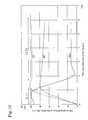
- FIG.3 An embodiment of cleaning the exhaust gas by this exhaust gas purifying system 1 is shown in Fig.3.
- the second exhaust gas purifying device 32 is provided with the NOx occlusion reduction type catalyst.
- Fig.3 illustrates the relation ship between the excess air factor ⁇ ent (full line A) at the entrance of the first exhaust gas purifying device 31 and the excess air factor ⁇ ext (dot-dash line B) at the exit of the first exhaust gas purifying device 31.
- Fig.3 illustrates the CO concentration (dot-dashed line C) at the downstream of the second exhaust gas purifying device 32 at that moment.
- Fig.3 also illustrates the excess air factor ⁇ ext (dashed line B') at the exit of the NOx occlusion reduction type catalyst 31 and the CO concentration (dashed line C') at the downstream of the NOx occlusion reduction type catalyst 31X, in the case that the second exhaust gas purifying device 32 is not arranged (the example for comparison).
Abstract
Description
- The present invention relates to an exhaust gas purifying system for an internal combustion engine, composed of a NOx occlusion reduction type catalyst which reduces NOx (nitrogen oxides) in the exhaust gas of the internal combustion engine. To be more concrete, the invention relates to the technique for preventing HC, CO from being exhausted into the atmospheric air during rich-condition control for restoring the catalytic function of the NOx occlusion reduction type catalyst.
- Various kinds of researches and proposals have been made concerning an NOx catalyst for reducing and purifying NOx in the exhaust gas of the internal combustion engines such as diesel engines and a part of gasoline engines, and various combustion systems.
- One of them is the exhaust gas purifying
system 1X where a NOx occlusionreduction type catalyst 31X is arranged in theexhaust gas passage 30 of theinternal combustion engine 10 as shown in Fig.4. This exhaust gas purifyingsystem 1X makes the NOx occlusionreduction type catalyst 31X absorb NOx when an air/fuel ratio of the inflow exhaust gas is lean. The regenerating operation is performed, when the NOx occlusion ability is almost saturated. In this regenerating operation, rich control for regenerating the NOx occlusion ability is performed to decrease the oxygen concentration of the inflow exhaust gas by making an air/fuel ratio of the exhaust gas to the theoretical air/fuel ratio or rich. The occluded NOx is discharged in the process. This discharged NOx is reduced by the catalytic function of an attached noble metal catalyst. - As shown in Fig. 5 to 7, this NOx occlusion reduction type catalyst, a noble metal catalyst 31Xb and a NOx occluding material (NOx occluding substance) 31Xc on a catalyst carrier 31Xa such as alumina. The noble metal catalyst 31Xb is composed of platinum (Pt), palladium (Pd), or the like. The NOx occluding material (NOx occluding substance) 31Xc is composed of alkaline-earth metal such as barium (Ba). As shown in Fig.5, in a lean (high oxygen concentration) atmosphere, NO in the exhaust gas is oxidized to NO2 by the catalytic action of the noble metal catalyst 31Xb. This NO2 is diffused in the catalyst in the form of NO3 -, and occluded in the NOx occluding material 31Xc in the form of a nitrate.
- When the air/fuel ratio become rich and the oxygen concentration is decreased as shown in Fig.6, NO3 - is discharged from the NOx occluding material 31Xc in the form of NO2. This NO2 is reduced to N2 with the reducer such as the unburned HC, CO, and H2 contained in the exhaust gas by the catalytic action of the noble metal catalyst 31Xb. This catalytic action prevents NOx from being discharged into the atmospheric air.
- Moreover, with this NOx occlusion reduction type catalyst, the sulfur contained in the fuel of a diesel engine is accumulated in the NOx occluding material, to be stabilized as a sulfate. Therefore, an occlusion quantity of NOx is reduced. The catalyst deterioration by sulfur poisoning develops, as the purifying rate of NOx is lowered and fuel cost is increased. For this reason, when the catalyst deterioration has developed to some extent, sulfur purge is carried to remove the sulfur.
- By this sulfur purge, the sulfur (S) occluded in the NOx occluding material as barium sulfate (Ba2PO4) is made into sulfur dioxide (SO2) by bringing the catalyst into a high temperature and oxygenless atmosphere, and also supplying carbon oxide (CO) thereto. Thus, the NOx occluding ability is restored.
- Hereafter, rich control is performed for both of the rich control for restoring the NOx occluding ability and the sulfur purge control. Therefore, both of them shall be summarized and called rich control hereafter.
- In this rich control, as shown in Fig.8, an excess air factor λ ext (dashed line B) at the catalyst exit is higher than an excess air factor λ ent (full line A) at the catalyst entrance during the first term R1 of the rich control but quickly decreases in the second term R2 to the same level as the excess air factor λ ent or lower.
- Therefore, for example, according to the Japanese Patent Laid-Open No. 10-121944 (121944/1998), an oxygen concentration difference before and after the catalyst is monitored, and when this oxygen concentration difference becomes small or the oxygen concentration at the catalyst exit falls lower than the oxygen concentration at the catalyst entrance, the discharge and reduction of NO2 in the catalyst is judged as completed and the rich control is ended at that point Re.
- However, at the same time as the change of the oxygen concentrations difference before and after the catalyst, an outflow of the reducers such as HC and CO is caused. Therefore, there is a problem that the reducers such as HC and CO throw out into the atmospheric air to some extent, if the rich control is ended after the changes in the oxygen concentrations are detected by the oxygen concentration sensors. Namely, as shown in Fig.9, the CO discharge (full line E') is increased at the same time as the rich control is ended.
- This reason is as follows. As shown in Fig.6, in the first term R1 of the rich control, O2 is supplied into the exhaust gas by the oxidation-reduction reaction of NO2 discharged from the occluding material 31Xc. However, as shown in Fig.7, in the second term R2 of the rich control, the supply of O2 into the exhaust gas is also ended at the same time as the discharge and reduction of NO2 are ended. Therefore, CO is also no longer oxidized and flows out into the atmosphere.
- In order to prevent this reducer from flowing out into the atmospheric air, for example, the exhaust gas purifying system for the internal combustion engine disclosed by the Japanese Patent NO.2658753 is provided with a secondary air-feeding device in the exhaust gas passage of the internal combustion engine. When the air/fuel ratio is changed from lean to rich, the secondary air is fed into the exhaust gas passage of the engine from the secondary air-feeding device so as to oxidize the excessive unburned components exhausted from the NOx occluding material.
- However, in order to arrange the secondary air-feeding device, an electric air pump, a secondary air-feeding pipe for feeding the secondary air from the secondary air-feeding device into the exhaust gas passage of the engine, an electromagnetic secondary air valve for controlling the supply of the secondary air, or the like are necessary. Therefore, the structure of such exhaust gas treating system is too complex and costly.
- The present invention has been made to resolved the above-mentioned problems, and the purpose thereof is to provide an exhaust gas purifying system for an internal combustion engine capable of preventing HC and CO from being discharged into the atmospheric air at the time of ending the rich control, by arranging a secondary exhaust gas purifying device composed of an oxidation catalyst or the like with an oxygen occluding function for purifying HC and CO at the downstream of an NOx occlusion reduction type catalyst, in an exhaust gas purifying system using a NOx occlusion reduction type catalyst for purifying NOx in the exhaust gas.
- The exhaust gas purifying system for an internal combustion engine to achieve the purposes as the above is the exhaust gas purifying system which comprises a first exhaust gas purifying device comprising an NOx occlusion reduction type catalyst in the exhaust gas passage of the internal combustion engine, and also comprises oxygen concentration detection sensors at the upstream and downstream of the first exhaust gas purifying device, respectively, and controls to end the rich control when a difference between the oxygen concentrations detected by both of the oxygen concentration sensors falls not higher than a predetermined judgment value during the rich control for restoring the catalytic ability of the first exhaust gas purifying system, and further comprises a second exhaust gas purifying device for purifying HC and CO at the downstream of the first exhaust gas purifying device.
- Further, in the above-mentioned exhaust gas purifying system for the internal combustion engine, the second exhaust gas purifying device is composed of any one of the NOx occlusion reduction type catalyst, a DPF (diesel particular filter) supporting the NOx occlusion reduction type catalyst, a three-way catalyst, and an oxidation catalyst with oxygen occluding function, or a combination of some of these.
- Moreover, the rich control for restoring the catalytic function of this first exhaust gas purifying device includes the rich control for restoring the NOx occluding ability and the rich control for purging sulfur for letting the catalyst restore from deterioration caused by sulfur poisoning. And also the expressions of the oxygen concentration sensors and the oxygen concentrations include the indications to be related with the oxygen concentrations such as an excess air factor sensor and an excess air factor even though the indication modes are different.
- According to the exhaust gas purifying system related to the present invention, the second exhaust gas purifying device for purifying HC and CO is arranged at the downstream of the first exhaust gas purifying device, therefore, the reducers such as HC and CO, which have been generated at the time of ending the rich control with the conventional technology, can be prevented from flowing out into the atmospheric air.
-
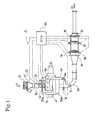
- Fig. 1 shows a construction of the exhaust gas purifying system in an embodiment according to the present invention.
- Fig. 2 shows an example of a control flow chart of the exhaust gas purifying system in an embodiment according to the present invention.
- Fig. 3 shows the excess air factors and carbon monoxide concentration of the exhaust gas in an embodiment and an example
- Fig. 4 shows a construction of the exhaust gas purifying system according to the conventional technology.
- Fig. 5 diagrammatically illustrates the configuration of the NOx occlusion reduction type catalyst and the purifying mechanism in the lean state of the lean control (the occlusion of NOx).
- Fig. 6 diagrammatically illustrates the configuration of the NOx occlusion reduction type catalyst and the purifying mechanism in the first term state of the rich control (R1: discharging and reducing).
- Fig. 7 diagrammatically illustrates the configuration of the NOx occlusion reduction type catalyst and the purifying mechanism in the second term state of the rich control (R2: after the discharge of the NOx).
- Fig. 8 is a chart showing the variations of the excess air factor λ ent at the catalyst entrance and the excess air factor λ ext at the catalyst exit during the rich control in the exhaust gas purifying system according to the conventional technology.
- Fig. 9 shows an outflow situation of carbon monoxide at the time of ending the rich control in the exhaust gas purifying system according to the conventional technology.
- Fig. 10 shows the relationships of the purifying factors of NOx, HC, and CO to oxygen concentrations with the NOx reduction type catalyst.
-
- In the following, the exhaust gas purifying system for an internal combustion engine in the embodiment according to the present invention will be explained referring to the drawings.
- As shown in Fig.1, this exhaust gas purifying
system 1 is comprised of the first exhaust gas purifyingdevice 31 for purifying NOx, and the second exhaust gas purifyingdevice 32 having a function of purifying the reducers such as HC and CO in the exhaust gas passage of theengine 10 from the upstream side. - This exhaust gas purifying
system 1 is provided with anair cleaner 21, anair flow meter 22, a MAF (mass air flow)sensor 23, and anintake throttle valve 24 from the upstream side in theintake passage 20 of theengine 10. - Moreover, in the
exhaust gas passage 30, the first exhaust gas purifyingdevice 31 and the second exhaust gas purifyingdevice 32 are arranged. This first exhaust gas purifyingdevice 31 is composed of the NOx occlusion reduction type catalyst. Moreover, the second exhaust gas purifyingdevice 32 is composed of any one of an NOx occlusion reduction type catalyst, a DPF supporting the NOx occlusion reduction type catalyst, an oxidation catalyst with an oxygen occluding function, and a three-way catalyst, or a combination of some of these. - Further, in the
exhaust gas passage 30, an exhaustgas temperature sensor 33, a catalyst entrance exhaustgas concentration sensor 34, a catalyst exit exhaustgas concentration sensor 35, a catalystentrance temperature sensor 36, and a catalystexit temperature sensor 37 are arranged. These exhaustgas concentration sensors - Moreover, an
EGR passage 40 is arranged, and in thisEGR passage 40, anEGR cooler 41 and anEGR valve 42 are arranged. - The
engine 10 with the exhaustgas purifying system 1 is provided with a common-rail injection system 50 for performing fuel injection, and an electronic control device (electronic control box) 60 called an ECU (engine control unit) to carry out the whole control for theengine 10. - In this exhaust
gas purifying system 1, the air A, passing through theair cleaner 21, theair flow meter 22, theMAF sensor 23, and theintake throttle valve 24, is fed into the cylinders through theintake manifold 20a of theengine 10. The flow rate of the air A is regulated by the control of theintake throttle valve 24 which is controlled by theelectronic control device 50. - Moreover, the exhaust gas G, coming out of the an
exhaust manifold 30a and sequentially passing through the first exhaustgas purifying device 31 and the second exhaustgas purifying device 32 in theexhaust gas passage 30, is exhausted from a tail pipe (not illustrated) through a muffler (not illustrated). This exhaust gas G is cleaned by the first exhaustgas purifying device 31 and the second exhaustgas purifying device 32 into cleaned exhaust gas Gc. - After passing through the
EGR passage 40 and being cooled through theEGR cooler 41, the EGR gas Ge, a part of the exhaust gas G is re-circulated into theintake manifold 20a through theEGR valve 42. TheEGR valve 42 regulates the flow rate of the EGR gas Ge and makes the EGR operation on or off. - As shown in Fig.5 - Fig.7, the NOx occlusion reduction type catalyst in the first exhaust
gas purifying device 31 is composed of a catalytic metal 31Xb and a NOx occluding material (NOx occluding substance) 31Xc which are carried on the surface of a carrier body 31Xa formed of monolithic honeycomb cells made of γ -alumina or the like. - This catalytic metal (noble metal catalyst) 31Xb can be composed of platinum (Pt), Palladium (Pd), or the like having oxidation activity in the temperature area higher than the activity start temperature. Moreover, the NOx occluding material (NOx absorbent) 31Xc can be composed of any one of an alkaline metal, an alkaline earth metal, and a rare earth metal, or a combination of them. The alkaline metals include potassium (K), sodium (Na), lithium (Li), cesium (Cs), or the like. The alkaline earth metals include barium (Ba), calcium (Ca), or the like. Moreover, the rare earth metals include lanthanum (La), yttrium (Y), or the like. This NOx occluding material 31Xc occludes NOx when the oxygen concentration in the gas is high, and discharges NOx when the oxygen concentration in the gas is low.
- As shown in Fig.5, NO in the exhaust gas is oxidized to NO2 by the catalytic action of the catalytic metal 31Xb in a high oxygen concentration atmosphere in which the exhaust gas is of the lean state (lean combustion). This NO2 diffuses in the catalyst in the form of NO3 -, and is absorbed in the NOx occluding material 31Xc in the form of a nitrate (Ba (NO3)2). Namely, NO2 is selectively occluded in the NOx occluding material 31Xc by changing from barium carbonate (BaCO3) into barium nitrate (Ba (NO3)2).
- As shown in Fig.6, NO3 - changes into NO2 when the exhaust gas is brought into the rich state and the oxygen concentration decreases, and NO2 is discharged from the NOx occluding material 31Xc. Namely, NO2 is discharged by changing from barium nitrate (Ba (NO3)2) into barium carbonate (BaCO3). This discharged NO2 is reduced to N2 with the reducers such as unburned HC and CO contained in the exhaust gas by the catalytic action of the catalytic metal 31Xb. This catalytic action is able to prevent NOx from being discharged into the atmospheric air.
- To make the exhaust gas rich-condition as described above does not always mean only rich combustion in the cylinder bores, but also means that a ratio of an air quantity to a fuel quantity (including the portion burned in the cylinder bores) which have been supplied into the exhaust gas flowing into the first exhaust
gas purifying device 31 with the NOx occlusion reduction type catalyst has only to be close to the theoretical air-fuel ratio or to be in a rich state in which the fuel quantity is more than that at the theoretical air-fuel ratio. - Moreover, the NOx occlusion reduction type catalyst carried in the second exhaust
gas purifying device 32 is a NOx occlusion reduction type catalyst similar to the catalyst in the first exhaustgas purifying device 31. Moreover, the DPF (diesel particulate filter) supporting the NOx occlusion reduction type catalyst is made to support a NOx occlusion reduction type catalyst similar to the catalyst in the first exhaustgas purifying device 31 on the DPF. - The three-way catalyst is the one used conventionally, and the oxidation catalyst with the oxygen occluding function is a conventional oxidation catalyst added with CeO2 (cerium oxide) or the like as an OSC agent (oxygen occluding material, oxygen absorbent).
- This exhaust
gas purifying system 1 is controlled by the method according to the control flow as shown in Fig.2 as an example. - This control flow in Fig.2 is shown repeatedly called and executed together with another control flow for the
engine 10 during operating theengine 10. - When this control flow starts, it is judged whether or not the rich control for restoring the NOx occluding ability or purging sulfur is required at the step S11. If it is not required (NO), normal lean mode operation that is normal lean-burn operation (lean combustion) is performed for a predetermined time (a time related to a judgment interval of rich control) at the step S14, and then the control flow returns.
- Moreover, if the rich control is required (YES) at the step S11, the rich control is performed at the step S12.
- This rich control brings the exhaust gas into the rich state in which the oxygen concentration is almost zero, by adjusting an injection quantity of multi-step injection and injection timing in the control of the fuel injection into the cylinders, EGR, the intake throttle valve, or the like. Namely, the multi-step injection is performed in the fuel injection control. At the same time, an excess air factor λ detected from the catalyst exit exhaust
gas concentration sensor 35 is monitored and controlled by feedback so as to be λ t as a target. Then, the EGR gas quantity and the intake throttle quantity are controlled by feedback while monitoring the output of theMAF sensor 23 for measuring the intake air quantity. - In this rich control, the controlled range of the rich atmosphere is controlled on the basis of an oxygen concentration. The oxygen concentration at the catalyst entrance needs to be controlled so as to be a concentration (for example 1%) or lower in which NO2 can be discharged from the NOx occluding material 31Xc. And also the oxygen concentration at the catalyst exit needs to be controlled so as to be a concentration (for example 1%) or higher in which HC and CO can be oxidized and are not caused to flow out into the atmospheric air.
- After having performed this rich control for a predetermined control time (a time related to an interval for judging to end the rich control), it is judged at the step S13 whether or not the difference (Δ λ = λ ext - λ ent) between the excess air factor λ ext at the catalyst exit and the excess air factor λ ent at the catalyst entrance is a predetermined judgment value Δ λ th or lower. Namely, it is judged whether or not the difference between the oxygen concentration at the catalyst exit and the oxygen concentration at the catalyst entrance is a predetermined concentration difference or smaller, namely, is not higher than the predetermined judgment value.
- If it is judged at the step S13 that the excess air factor difference Δ λ is larger than the predetermined judgment value Δ λ th, the control flow returns to the step S12 and the rich control is continued until the excess air factor difference Δ λ becomes the predetermined judgment value Δ λth or smaller. When the excess air factor difference Δ λ becomes the predetermined judgment value Δ λ th or smaller, the rich control is ended to be operated in the normal lean mode at the step S14, and then returns to the start.
- This control flow is repeatedly called for until the engine key is switched off.
- Namely, this control flow of starting, executing the steps S11 - S14 and returning to the start is repeatedly performed.
- Moreover, the above-mentioned flow is simplified for an easy understanding. Therefore, the descriptions of the data entry and data processing parts for judging the necessity for the rich control are omitted. And the descriptions of the difference in the rich control contents at the step S12 based on the difference between the rich control for restoring the NOx occluding ability and that for purging sulfur are omitted. Moreover, the descriptions of the process for writing the quantity of NOx, the quantity of sulfur and the lean-driving duration at the ending of engine operation into the memory, is also omitted.
- Next, the states of the exhaust gas during the first and second terms of the rich control and at the time of ending it in the exhaust
gas purifying system 1 of the above-mentioned configuration will be explained below. - During the first term (initial stage) of the rich control, the discharge and reduction of NO2 at the NOx occluding material 31Xc are not performed at the part Z1 in Fig. 10, unless the oxygen concentration in the atmosphere is at a certain level (about 1%) or lower. When the oxygen concentration is low, namely during Z1, NOx is reduced. Moreover, as shown in Fig.3, during the first term stage R1 of this rich control, the high oxygen concentration is measured at the catalyst exit, namely, the excess air factor λ ext is high. According to above-mentioned matter, it is presumed that the discharge and reduction of NO2 are started in the front part of the catalyst since the oxygen concentration at the catalyst entrance falls, and that the oxygen concentration in the rear part of the catalyst is increased due to the discharge and reduction of NO2 at the front part. And it is presumed that the oxidation-reduction function of CO and HC is stronger than the discharge function of NO2 at the part Z2 in Fig. 10. Practically, the outflows (slips) of HC, CO, and NOx from the catalyst exit are not caused. When the oxygen concentration is high, namely during Z2, the HC and CO are oxidized.
- Moreover, during the second term R2 of the rich control R, the discharge and reduction of NO2 are performed in the whole area of the catalyst, and when the reaction starts to end, the oxygen concentration in the rear side of the catalyst starts to fall, and falls to the same level as that in the front side of the catalyst or lower. Namely, as shown in Fig.3, the excess air factor λ ext starts to fall and approaches to the excess air factor λ ent. Since the oxygen concentration in the rear part of the catalyst is also lowered in this state during the part Z1 in Fig. 10, CO and HC begin to flow out to the downstream side of the catalyst without being oxidized.
- As described above, it is presumed that the discharge and reduction of NO2, and the oxidation of HC and CO are time-sequentially progressing from the front part to the rear part of the catalyst according to the change of the oxygen concentration inside of the NOx occlusion reduction type catalyst in the first exhaust gas purifying device.
- As the rich control progresses, the discharge and reduction of NO2 proceed in the catalyst, and the rich control approaches to an end, the oxygen concentration at the catalyst exit falls to the same level as that at the catalyst entrance or lower. Namely, the difference between the outputs of the oxygen concentration sensors approaches to a predetermined judgment value and exceeds this predetermined judgment value. Namely, the difference Δ λ between the excess air factors exceeds the predetermined judgment value Δ λ ent. The rich control is ended at this point Re.
- However, in the present invention, the second exhaust
gas purifying device 32 is located at the downstream of the first exhaustgas purifying device 31. Therefore, at this ending stage of the rich control R, the reducers such as HC and CO flowing out of the first exhaustgas purifying device 31 can be purified by the second exhaustgas purifying device 32. Therefore, these reducers can be prevented from flowing out into the atmospheric air. - Namely, in the case that the second exhaust
gas purifying device 32 is provided with the NOx occlusion reduction type catalyst or the DPF with the NOx occlusion reduction type catalyst, the discharge and reduction of NO2 is in progress in this second exhaustgas purifying device 32 and the oxygen is high in the concentration. The reducers such as HC and CO flowing out of the first exhaustgas purifying device 31 at the upstream are consumed for reducing NO2. Namely, since HC and CO are oxidized by this reduction, the reducers such as HC and CO can be prevented from flowing out into the atmospheric air. - Moreover, in the case that the second exhaust
gas purifying device 32 is provided with the three-way catalyst or the oxidation catalyst having the oxygen occluding function, HC and CO are reduced by O2 discharged from these catalysts, therefore, the reducers such as HC and CO can be prevented from flowing out into the atmospheric air in the similar way. - Therefore, the exhaust
gas purifying system 1 of the configuration described above performs the rich control when it is required, and purifies HC and CO which are not oxidized through at the time of ending the rich control on the basis of the difference between the oxygen concentrations before and after the first exhaustgas purifying device 31, by the second exhaustgas purifying device 32 at the downstream side. Accordingly HC and CO can be prevented from being discharged into the atmospheric air. - An embodiment of cleaning the exhaust gas by this exhaust
gas purifying system 1 is shown in Fig.3. In this embodiment, the second exhaustgas purifying device 32 is provided with the NOx occlusion reduction type catalyst. Fig.3 illustrates the relation ship between the excess air factor λ ent (full line A) at the entrance of the first exhaustgas purifying device 31 and the excess air factor λ ext (dot-dash line B) at the exit of the first exhaustgas purifying device 31. And Fig.3 illustrates the CO concentration (dot-dashed line C) at the downstream of the second exhaustgas purifying device 32 at that moment. Moreover, Fig.3 also illustrates the excess air factor λ ext (dashed line B') at the exit of the NOx occlusionreduction type catalyst 31 and the CO concentration (dashed line C') at the downstream of the NOx occlusionreduction type catalyst 31X, in the case that the second exhaustgas purifying device 32 is not arranged (the example for comparison). - Comparing the CO concentration (dot-dashed line C) of this embodiment with the CO concentration (dashed line C') of the example for comparison, the outflow of CO at the time of ending the rich control has disappeared in the embodiment. So, the effect of the present invention is apparent.
Claims (2)
- An exhaust gas purifying system for an internal combustion engine, comprising a first exhaust gas purifying device composed of a NOx occlusion reduction type catalyst arranged in the exhaust passage of an internal combustion engine, and also comprising the respective oxygen concentration sensors arranged at the upstream and downstream of the first exhaust gas purifying device, and which controls to end the rich control when a difference between the oxygen concentrations detected by both of said oxygen concentration sensors falls not higher than a predetermined judgment value during the rich control for restoring the catalytic ability of the first exhaust gas purging device, wherein a second exhaust gas purifying device for purifying HC and CO is arranged at the downstream of said first exhaust gas purifying device.
- An exhaust gas purifying system as claimed in claim 1, wherein said second exhaust gas purifying device is composed of any one of the NOx occlusion reduction type catalyst, a DPF supporting thereon the NOx occlusion reduction type catalyst, a three-way catalyst, and an oxidation catalyst with an oxygen occlusion function, or composed of a combination of some of these.
Applications Claiming Priority (2)
| Application Number | Priority Date | Filing Date | Title |
|---|---|---|---|
| JP2003031184 | 2003-02-07 | ||
| JP2003031184A JP4304428B2 (en) | 2003-02-07 | 2003-02-07 | Exhaust gas purification system for internal combustion engine |
Publications (2)
| Publication Number | Publication Date |
|---|---|
| EP1445441A1 true EP1445441A1 (en) | 2004-08-11 |
| EP1445441B1 EP1445441B1 (en) | 2006-07-26 |
Family
ID=32653019
Family Applications (1)
| Application Number | Title | Priority Date | Filing Date |
|---|---|---|---|
| EP04100354A Expired - Lifetime EP1445441B1 (en) | 2003-02-07 | 2004-02-02 | Exhaust gas purifying system for internal combustion engine |
Country Status (5)
| Country | Link |
|---|---|
| US (1) | US20040154285A1 (en) |
| EP (1) | EP1445441B1 (en) |
| JP (1) | JP4304428B2 (en) |
| CN (1) | CN1521390A (en) |
| DE (1) | DE602004001595T2 (en) |
Cited By (6)
| Publication number | Priority date | Publication date | Assignee | Title |
|---|---|---|---|---|
| FR2891584A1 (en) * | 2005-10-03 | 2007-04-06 | Renault Sas | Diesel engine controlling method for vehicle, involves introducing fuel in oxidation units of exhaust line of engine, and receiving measurement, of proportional probe, downstream of units |
| EP1788212A1 (en) * | 2004-09-09 | 2007-05-23 | Isuzu Motors Limited | Guide structure and exhaust emission control device |
| DE102005058858A1 (en) * | 2005-12-09 | 2007-06-14 | Volkswagen Ag | Method for exhaust gas aftertreatment in internal combustion engines, and apparatus for carrying out this method |
| EP1801379A1 (en) * | 2004-10-15 | 2007-06-27 | Toyota Jidosha Kabushiki Kaisha | Exhaust gas purification system for internal combustion engine |
| FR2956988A1 (en) * | 2010-03-05 | 2011-09-09 | Peugeot Citroen Automobiles Sa | Exhaust gas filtering device for e.g. natural gas engine of car, has particle filter impregnated with oxygen storage capacity material, where initial quantity of material is sufficient to store specific amount of oxygen per liter of filter |
| US10890092B2 (en) | 2017-02-10 | 2021-01-12 | Toyota Jidosha Kabushiki Kaisha | Internal combustion engine and method for controlling internal combustion engine |
Families Citing this family (20)
| Publication number | Priority date | Publication date | Assignee | Title |
|---|---|---|---|---|
| CN100420829C (en) * | 2003-12-01 | 2008-09-24 | 丰田自动车株式会社 | Exhaust emission purification apparatus of compression ignition type internal combustion engine |
| US7111451B2 (en) * | 2004-09-16 | 2006-09-26 | Delphi Technologies, Inc. | NOx adsorber diagnostics and automotive exhaust control system utilizing the same |
| DE102005033395B4 (en) * | 2005-07-16 | 2007-06-06 | Umicore Ag & Co. Kg | Process for the regeneration of nitrogen oxide storage catalysts |
| DE102005061872A1 (en) * | 2005-12-23 | 2007-07-05 | Robert Bosch Gmbh | Regeneration of motor vehicle internal combustion engine exhaust gas catalyst comprises use of two gas mixture sensors to control reduction agent mix |
| JP5003042B2 (en) * | 2006-07-14 | 2012-08-15 | いすゞ自動車株式会社 | Exhaust gas purification system |
| JP4327837B2 (en) | 2006-12-01 | 2009-09-09 | トヨタ自動車株式会社 | Exhaust gas purification device |
| US20080190099A1 (en) * | 2006-12-20 | 2008-08-14 | Aleksey Yezerets | System and method for inhibiting uncontrolled regeneration of a particulate filter for an internal combustion engine |
| JP4998714B2 (en) * | 2007-03-30 | 2012-08-15 | 三菱自動車工業株式会社 | Exhaust gas purification device for internal combustion engine |
| JP4973992B2 (en) * | 2007-07-11 | 2012-07-11 | トヨタ自動車株式会社 | Exhaust gas purification device for internal combustion engine |
| JP5590640B2 (en) * | 2007-08-01 | 2014-09-17 | 日産自動車株式会社 | Exhaust gas purification system |
| JP5067614B2 (en) * | 2007-08-21 | 2012-11-07 | 株式会社デンソー | Exhaust gas purification device for internal combustion engine |
| US8291695B2 (en) * | 2008-12-05 | 2012-10-23 | GM Global Technology Operations LLC | Method and apparatus for controlling exhaust emissions in a spark-ignition direct-injection engine |
| EP2434134B1 (en) * | 2009-05-21 | 2014-11-19 | Toyota Jidosha Kabushiki Kaisha | Air-fuel ratio control device for internal-combustion engine |
| DE102009022882A1 (en) | 2009-05-27 | 2010-12-02 | Bayerische Motoren Werke Aktiengesellschaft | A sensor for detecting the amount of a reducing agent and the amount of a pollutant in an exhaust gas |
| US8304366B2 (en) * | 2010-11-24 | 2012-11-06 | Ford Global Technologies, Llc | System for remediating emissions and method of use |
| JPWO2013175604A1 (en) * | 2012-05-24 | 2016-01-12 | トヨタ自動車株式会社 | Exhaust gas purification device for internal combustion engine |
| GB2512648B (en) * | 2013-04-05 | 2018-06-20 | Johnson Matthey Plc | Filter substrate comprising three-way catalyst |
| JP6544392B2 (en) * | 2017-07-20 | 2019-07-17 | トヨタ自動車株式会社 | Diagnosis system for exhaust purification system |
| CN108825345A (en) * | 2018-06-19 | 2018-11-16 | 贵州大学 | A kind of hazardous materials transportation vehicle exhaust pipe that shockproof effect is good |
| CN114674976B (en) * | 2022-02-23 | 2023-12-05 | 福建省永正生态科技有限公司 | Carbon monoxide concentration detector for occupational health detection |
Citations (5)
| Publication number | Priority date | Publication date | Assignee | Title |
|---|---|---|---|---|
| EP0735250A2 (en) * | 1995-03-28 | 1996-10-02 | Toyota Jidosha Kabushiki Kaisha | Device for detecting deterioration of NOx absorbent |
| US5743084A (en) * | 1996-10-16 | 1998-04-28 | Ford Global Technologies, Inc. | Method for monitoring the performance of a nox trap |
| EP1138898A2 (en) * | 2000-03-28 | 2001-10-04 | Volkswagen AG | Method and device for purification of exhaust gases |
| WO2002084086A1 (en) * | 2001-04-13 | 2002-10-24 | Yanmar Co., Ltd. | Exhaust gas cleaner for internal combustion engine |
| US6477834B1 (en) * | 1997-05-12 | 2002-11-12 | Toyota Jidosha Kabushiki Kaisha | Exhaust emission controlling apparatus of internal combustion engine |
Family Cites Families (6)
| Publication number | Priority date | Publication date | Assignee | Title |
|---|---|---|---|---|
| JP3266699B2 (en) * | 1993-06-22 | 2002-03-18 | 株式会社日立製作所 | Catalyst evaluation method, catalyst efficiency control method, and NOx purification catalyst evaluation apparatus |
| JP2858288B2 (en) * | 1993-09-02 | 1999-02-17 | 株式会社ユニシアジェックス | Self-diagnosis device in air-fuel ratio control device of internal combustion engine |
| JPH0886238A (en) * | 1994-09-16 | 1996-04-02 | Honda Motor Co Ltd | Air-fuel ratio controller of internal combustion engine |
| JP3709655B2 (en) * | 1997-06-09 | 2005-10-26 | 日産自動車株式会社 | Exhaust gas purification device for internal combustion engine |
| US6237330B1 (en) * | 1998-04-15 | 2001-05-29 | Nissan Motor Co., Ltd. | Exhaust purification device for internal combustion engine |
| JP3759578B2 (en) * | 2000-09-01 | 2006-03-29 | 株式会社デンソー | Deterioration detection device for exhaust gas purification catalyst |
-
2003
- 2003-02-07 JP JP2003031184A patent/JP4304428B2/en not_active Expired - Fee Related
-
2004
- 2004-02-02 DE DE602004001595T patent/DE602004001595T2/en not_active Expired - Lifetime
- 2004-02-02 EP EP04100354A patent/EP1445441B1/en not_active Expired - Lifetime
- 2004-02-04 US US10/770,393 patent/US20040154285A1/en not_active Abandoned
- 2004-02-06 CN CNA2004100038293A patent/CN1521390A/en active Pending
Patent Citations (6)
| Publication number | Priority date | Publication date | Assignee | Title |
|---|---|---|---|---|
| EP0735250A2 (en) * | 1995-03-28 | 1996-10-02 | Toyota Jidosha Kabushiki Kaisha | Device for detecting deterioration of NOx absorbent |
| US5743084A (en) * | 1996-10-16 | 1998-04-28 | Ford Global Technologies, Inc. | Method for monitoring the performance of a nox trap |
| US6477834B1 (en) * | 1997-05-12 | 2002-11-12 | Toyota Jidosha Kabushiki Kaisha | Exhaust emission controlling apparatus of internal combustion engine |
| EP1138898A2 (en) * | 2000-03-28 | 2001-10-04 | Volkswagen AG | Method and device for purification of exhaust gases |
| WO2002084086A1 (en) * | 2001-04-13 | 2002-10-24 | Yanmar Co., Ltd. | Exhaust gas cleaner for internal combustion engine |
| EP1384866A1 (en) * | 2001-04-13 | 2004-01-28 | Yanmar Co., Ltd. | Exhaust gas cleaner for internal combustion engine |
Cited By (10)
| Publication number | Priority date | Publication date | Assignee | Title |
|---|---|---|---|---|
| EP1788212A1 (en) * | 2004-09-09 | 2007-05-23 | Isuzu Motors Limited | Guide structure and exhaust emission control device |
| EP1788212A4 (en) * | 2004-09-09 | 2010-05-26 | Isuzu Motors Ltd | Guide structure and exhaust emission control device |
| US7963109B2 (en) | 2004-09-09 | 2011-06-21 | Isuzu Motors Limited | Guide structure and exhaust gas purification device |
| EP1801379A1 (en) * | 2004-10-15 | 2007-06-27 | Toyota Jidosha Kabushiki Kaisha | Exhaust gas purification system for internal combustion engine |
| EP1801379A4 (en) * | 2004-10-15 | 2010-06-02 | Toyota Motor Co Ltd | Exhaust gas purification system for internal combustion engine |
| US7832199B2 (en) | 2004-10-15 | 2010-11-16 | Toyota Jidosha Kabushiki Kaisha | Exhaust purification system for internal combustion engine |
| FR2891584A1 (en) * | 2005-10-03 | 2007-04-06 | Renault Sas | Diesel engine controlling method for vehicle, involves introducing fuel in oxidation units of exhaust line of engine, and receiving measurement, of proportional probe, downstream of units |
| DE102005058858A1 (en) * | 2005-12-09 | 2007-06-14 | Volkswagen Ag | Method for exhaust gas aftertreatment in internal combustion engines, and apparatus for carrying out this method |
| FR2956988A1 (en) * | 2010-03-05 | 2011-09-09 | Peugeot Citroen Automobiles Sa | Exhaust gas filtering device for e.g. natural gas engine of car, has particle filter impregnated with oxygen storage capacity material, where initial quantity of material is sufficient to store specific amount of oxygen per liter of filter |
| US10890092B2 (en) | 2017-02-10 | 2021-01-12 | Toyota Jidosha Kabushiki Kaisha | Internal combustion engine and method for controlling internal combustion engine |
Also Published As
| Publication number | Publication date |
|---|---|
| JP2004239218A (en) | 2004-08-26 |
| US20040154285A1 (en) | 2004-08-12 |
| DE602004001595T2 (en) | 2007-07-12 |
| CN1521390A (en) | 2004-08-18 |
| EP1445441B1 (en) | 2006-07-26 |
| DE602004001595D1 (en) | 2006-09-07 |
| JP4304428B2 (en) | 2009-07-29 |
Similar Documents
| Publication | Publication Date | Title |
|---|---|---|
| EP1445441B1 (en) | Exhaust gas purifying system for internal combustion engine | |
| JP4415648B2 (en) | Sulfur purge control method and exhaust gas purification system | |
| EP1793099B1 (en) | Method of exhaust gas purification and exhaust gas purification system | |
| JP4175427B1 (en) | NOx purification system control method and NOx purification system | |
| US20050109022A1 (en) | Exhaust gas purifying method and exhaust gas purifying system | |
| EP1491735A1 (en) | Exhaust gas decontamination system and method of controlling the same | |
| JP5217102B2 (en) | NOx purification system control method and NOx purification system | |
| JP5900728B2 (en) | Engine exhaust purification system | |
| EP1176298B1 (en) | Emission control system and method for internal combustion engine | |
| US7114328B2 (en) | Control method of exhaust gas purifying system | |
| JP3624815B2 (en) | Exhaust gas purification device for internal combustion engine | |
| JP4075641B2 (en) | Exhaust gas purification system for internal combustion engine | |
| JP4144584B2 (en) | Exhaust gas purification device for internal combustion engine | |
| JP2010127182A (en) | Exhaust emission control device for internal combustion engine | |
| JP4175031B2 (en) | Exhaust gas purification device for internal combustion engine | |
| JP2004036405A (en) | Exhaust emission control device | |
| JP2006161668A (en) | Exhaust emission control system and desulfurization control method for exhaust emission control system | |
| JP3480431B2 (en) | Exhaust gas purification device for internal combustion engine | |
| JP2002038929A (en) | Exhaust emission control device of internal combustion engine | |
| JP2006083746A (en) | Exhaust emission control method and exhaust emission control system |
Legal Events
| Date | Code | Title | Description |
|---|---|---|---|
| PUAI | Public reference made under article 153(3) epc to a published international application that has entered the european phase |
Free format text: ORIGINAL CODE: 0009012 |
|
| AK | Designated contracting states |
Kind code of ref document: A1 Designated state(s): AT BE BG CH CY CZ DE DK EE ES FI FR GB GR HU IE IT LI LU MC NL PT RO SE SI SK TR |
|
| AX | Request for extension of the european patent |
Extension state: AL LT LV MK |
|
| 17P | Request for examination filed |
Effective date: 20041105 |
|
| 17Q | First examination report despatched |
Effective date: 20041209 |
|
| AKX | Designation fees paid |
Designated state(s): DE FR GB IT |
|
| GRAP | Despatch of communication of intention to grant a patent |
Free format text: ORIGINAL CODE: EPIDOSNIGR1 |
|
| RIN1 | Information on inventor provided before grant (corrected) |
Inventor name: GABE, MASASHI Inventor name: SAKAMOTO, TAKAYUKI Inventor name: NAGAOKA, DAIJI |
|
| GRAS | Grant fee paid |
Free format text: ORIGINAL CODE: EPIDOSNIGR3 |
|
| GRAA | (expected) grant |
Free format text: ORIGINAL CODE: 0009210 |
|
| AK | Designated contracting states |
Kind code of ref document: B1 Designated state(s): DE FR GB IT |
|
| PG25 | Lapsed in a contracting state [announced via postgrant information from national office to epo] |
Ref country code: IT Free format text: LAPSE BECAUSE OF FAILURE TO SUBMIT A TRANSLATION OF THE DESCRIPTION OR TO PAY THE FEE WITHIN THE PRESCRIBED TIME-LIMIT;WARNING: LAPSES OF ITALIAN PATENTS WITH EFFECTIVE DATE BEFORE 2007 MAY HAVE OCCURRED AT ANY TIME BEFORE 2007. THE CORRECT EFFECTIVE DATE MAY BE DIFFERENT FROM THE ONE RECORDED. Effective date: 20060726 |
|
| REG | Reference to a national code |
Ref country code: GB Ref legal event code: FG4D |
|
| REF | Corresponds to: |
Ref document number: 602004001595 Country of ref document: DE Date of ref document: 20060907 Kind code of ref document: P |
|
| ET | Fr: translation filed | ||
| PLBE | No opposition filed within time limit |
Free format text: ORIGINAL CODE: 0009261 |
|
| STAA | Information on the status of an ep patent application or granted ep patent |
Free format text: STATUS: NO OPPOSITION FILED WITHIN TIME LIMIT |
|
| 26N | No opposition filed |
Effective date: 20070427 |
|
| PGFP | Annual fee paid to national office [announced via postgrant information from national office to epo] |
Ref country code: IT Payment date: 20080123 Year of fee payment: 5 |
|
| REG | Reference to a national code |
Ref country code: FR Ref legal event code: PLFP Year of fee payment: 13 |
|
| REG | Reference to a national code |
Ref country code: FR Ref legal event code: PLFP Year of fee payment: 14 |
|
| PGFP | Annual fee paid to national office [announced via postgrant information from national office to epo] |
Ref country code: FR Payment date: 20170112 Year of fee payment: 14 Ref country code: DE Payment date: 20170125 Year of fee payment: 14 |
|
| PGFP | Annual fee paid to national office [announced via postgrant information from national office to epo] |
Ref country code: GB Payment date: 20170201 Year of fee payment: 14 |
|
| REG | Reference to a national code |
Ref country code: DE Ref legal event code: R119 Ref document number: 602004001595 Country of ref document: DE |
|
| GBPC | Gb: european patent ceased through non-payment of renewal fee |
Effective date: 20180202 |
|
| REG | Reference to a national code |
Ref country code: FR Ref legal event code: ST Effective date: 20181031 |
|
| PG25 | Lapsed in a contracting state [announced via postgrant information from national office to epo] |
Ref country code: DE Free format text: LAPSE BECAUSE OF NON-PAYMENT OF DUE FEES Effective date: 20180901 |
|
| PG25 | Lapsed in a contracting state [announced via postgrant information from national office to epo] |
Ref country code: GB Free format text: LAPSE BECAUSE OF NON-PAYMENT OF DUE FEES Effective date: 20180202 Ref country code: FR Free format text: LAPSE BECAUSE OF NON-PAYMENT OF DUE FEES Effective date: 20180228 |