EP1445346B1 - Beschichtung aus Aluminid für Gasturbinenschaufel - Google Patents
Beschichtung aus Aluminid für Gasturbinenschaufel Download PDFInfo
- Publication number
- EP1445346B1 EP1445346B1 EP04250585A EP04250585A EP1445346B1 EP 1445346 B1 EP1445346 B1 EP 1445346B1 EP 04250585 A EP04250585 A EP 04250585A EP 04250585 A EP04250585 A EP 04250585A EP 1445346 B1 EP1445346 B1 EP 1445346B1
- Authority
- EP
- European Patent Office
- Prior art keywords
- coating
- gas
- aluminide coating
- blade
- aluminide
- Prior art date
- Legal status (The legal status is an assumption and is not a legal conclusion. Google has not performed a legal analysis and makes no representation as to the accuracy of the status listed.)
- Expired - Fee Related
Links
Images


Classifications
-
- C—CHEMISTRY; METALLURGY
- C23—COATING METALLIC MATERIAL; COATING MATERIAL WITH METALLIC MATERIAL; CHEMICAL SURFACE TREATMENT; DIFFUSION TREATMENT OF METALLIC MATERIAL; COATING BY VACUUM EVAPORATION, BY SPUTTERING, BY ION IMPLANTATION OR BY CHEMICAL VAPOUR DEPOSITION, IN GENERAL; INHIBITING CORROSION OF METALLIC MATERIAL OR INCRUSTATION IN GENERAL
- C23C—COATING METALLIC MATERIAL; COATING MATERIAL WITH METALLIC MATERIAL; SURFACE TREATMENT OF METALLIC MATERIAL BY DIFFUSION INTO THE SURFACE, BY CHEMICAL CONVERSION OR SUBSTITUTION; COATING BY VACUUM EVAPORATION, BY SPUTTERING, BY ION IMPLANTATION OR BY CHEMICAL VAPOUR DEPOSITION, IN GENERAL
- C23C10/00—Solid state diffusion of only metal elements or silicon into metallic material surfaces
- C23C10/06—Solid state diffusion of only metal elements or silicon into metallic material surfaces using gases
- C23C10/08—Solid state diffusion of only metal elements or silicon into metallic material surfaces using gases only one element being diffused
-
- F—MECHANICAL ENGINEERING; LIGHTING; HEATING; WEAPONS; BLASTING
- F01—MACHINES OR ENGINES IN GENERAL; ENGINE PLANTS IN GENERAL; STEAM ENGINES
- F01D—NON-POSITIVE DISPLACEMENT MACHINES OR ENGINES, e.g. STEAM TURBINES
- F01D5/00—Blades; Blade-carrying members; Heating, heat-insulating, cooling or antivibration means on the blades or the members
- F01D5/12—Blades
- F01D5/28—Selecting particular materials; Particular measures relating thereto; Measures against erosion or corrosion
- F01D5/288—Protective coatings for blades
-
- F—MECHANICAL ENGINEERING; LIGHTING; HEATING; WEAPONS; BLASTING
- F05—INDEXING SCHEMES RELATING TO ENGINES OR PUMPS IN VARIOUS SUBCLASSES OF CLASSES F01-F04
- F05D—INDEXING SCHEME FOR ASPECTS RELATING TO NON-POSITIVE-DISPLACEMENT MACHINES OR ENGINES, GAS-TURBINES OR JET-PROPULSION PLANTS
- F05D2230/00—Manufacture
- F05D2230/30—Manufacture with deposition of material
- F05D2230/31—Layer deposition
- F05D2230/313—Layer deposition by physical vapour deposition
-
- Y—GENERAL TAGGING OF NEW TECHNOLOGICAL DEVELOPMENTS; GENERAL TAGGING OF CROSS-SECTIONAL TECHNOLOGIES SPANNING OVER SEVERAL SECTIONS OF THE IPC; TECHNICAL SUBJECTS COVERED BY FORMER USPC CROSS-REFERENCE ART COLLECTIONS [XRACs] AND DIGESTS
- Y02—TECHNOLOGIES OR APPLICATIONS FOR MITIGATION OR ADAPTATION AGAINST CLIMATE CHANGE
- Y02T—CLIMATE CHANGE MITIGATION TECHNOLOGIES RELATED TO TRANSPORTATION
- Y02T50/00—Aeronautics or air transport
- Y02T50/60—Efficient propulsion technologies, e.g. for aircraft
Definitions
- the present invention relates to a method for applying a protective coating on a gas turbine engine blade having an internal cooling cavity. More particularly, the invention relates to the aluminide coating of the internal and external surfaces of such a gas turbine blade.
- the maximum temperature of the combustion gases is normally limited by the materials used to fabricate the turbine blades.
- the turbine blades are made of nickel-based superalloys, and can operate at metal temperatures of up to about 1900-2100°F (about 1038-1149°C).
- Turbine blades typically comprise cooling circuits that channel cooling air through the interior of the turbine airfoil to reduce temperatures encountered by the blade and improve part life.
- air is forced through the root portion of the blade, into the airfoil cooling chambers, and out openings at the external surface of the airfoil.
- the flow of the air removes heat from the interior of the airfoil and, in some cases, providing a boundary layer of cooler air at the surface of the airfoil.
- an abrupt transition extends between the root portion and the airfoil portion to increase the volume of cooling air entering the airfoil portion.
- Gas turbine blades frequently have metallic surface coatings that are capable of resisting the oxidation, corrosion and sulfidation conditions generated during high temperature operation. Such coatings facilitate the airfoil withstanding thermal stresses that may be induced within the higher operating temperature areas of the blade. However, if the coating is applied at too great a thickness on regions of the blade operating at lower temperatures, such as the root and shank region, the combination of the increased coating thickness and the abrupt transition within the dovetail may cause cracking in the root portion as higher stresses are induced into the transition area of the dovetail. Over time, continued operation may lead to a premature failure of the blade within the engine.
- the above coatings can be applied by depositing a vapor of one or more protective metals, for example aluminum or alloys of aluminum, on blade surfaces at high temperatures within a coating container or chamber commonly referred to as a "retort".
- a coating container or chamber commonly referred to as a "retort”.
- the blades to be coated are placed within the container, along with a source of the aluminide coating, typically in the form of metallic pellets retained in perforated baskets arranged in rows surrounding the blades.
- the coating container is then placed within a heater such as a furnace to generate an aluminide coating vapor.
- Generation of the coating vapor typically includes the use of halide "activators" such as fluorides, chlorides or bromides.
- the halide activator can be in the form of a gas that is introduced into the container to react with the source of the aluminide coating and form an aluminide-bearing gas, or it can be generated from a halide activator source within the container that forms a reactive halide gas upon heating.
- the aluminide-bearing gas is typically transported or moved within the coating container by a nonoxidizing or inert carrier gas (e.g., hydrogen, nitrogen, helium or argon).
- a nonoxidizing or inert carrier gas e.g., hydrogen, nitrogen, helium or argon
- this carrier gas is introduced through the bottom of the container and carries the aluminide-bearing gas upward to coat the blades.
- U.S. Patent 4,148,275 Benden et al), issued April 10, 1979; and U.S. Patent 5,928,725 (Howard et al), issued July 27, 1999.
- the carrier gas is introduced through the top of the coating container and diffuses throughout the container to carry the aluminide-bearing gas and coat the blades. See U.S. Patent 6,039,810 (Mantkowski et al), issued March 21, 2000.
- a controlled, relatively uniform aluminide coating be applied to the external and internal surfaces of the turbine blades. It is also desirable that the aluminide coating applied to internal surfaces of the blades, particularly in the root and shank region, be relatively thin (for example, having a thickness of from about 0.0005 to about 0.0015 inches) (from about 12.7 to about 38.1 ⁇ m (microns)) so as not to cause premature cracking in the root portion of the blade.
- this invention relates to a method for applying an aluminide coating on a gas turbine engine blade having an external surface and an internal cooling cavity defined by an internal surface that is connected to the external surface by cooling holes, the method being conducted in a vapor coating container having a hollow interior coating chamber, the method comprising the steps of:
- this invention relates to a method for applying an aluminide coating on a gas turbine engine blade having an external surface and an internal cooling cavity defined by an internal surface that is connected to the external surface by cooling holes, the method being conducted in a vapor coating container having a hollow interior coating chamber, the method comprising the steps of:
- FIG. 1 depicts a turbine blade 20 of a gas turbine engine.
- Turbine blade 20 may be formed of any operable material, but typically is a nickel-base superalloy.
- Blade 20 includes an airfoil 22 against which the flow of hot exhaust gas is directed.
- Blade 20 is mounted to a turbine disk (not shown) by a dovetail 24 that extends downwardly from the airfoil 22 and engages a slot on the turbine disk.
- a platform 26 extends longitudinally outwardly from the area where the airfoil 22 is joined to the dovetail 24.
- Airfoil 22 includes a first sidewall 28 and a second sidewall 30.
- First sidewall 28 is convex and defines a suction side of airfoil 22
- second sidewall 30 is concave and defines a pressure side of airfoil 22.
- Sidewalls 28 and 30 are joined at a leading edge 32 and at an axially-spaced trailing edge 34 of airfoil 22.
- Airfoil trailing edge 34 is spaced chordwise and downstream from airfoil leading edge 32.
- First and second sidewalls 28 and 30, respectively, extend longitudinally or radially outward in span from an airfoil root 36 positioned adjacent dovetail 24, to an oppositely disposed airfoil tip 38 remote from dovetail 24.
- Airfoil tip 38 defines a radially outer boundary of an internal cooling cavity (not shown in FIG. 1).
- the cooling cavity is bounded within airfoil 22 between sidewalls 28 and 30.
- blade 20 includes an internal surface (not shown in FIG. 1) and an external surface 40, and the cooling cavity is defined by the blade internal surface.
- a number of internal cooling chambers extend through the interior of airfoil 22, between airfoil first and second sidewalls 28 and 30, respectively, ending in a plurality of cooling holes 42 extending between the airfoil internal surface and airfoil external surface 40.
- a flow of cooling air is directed through the internal cooling chambers to reduce the temperature of the airfoil 22.
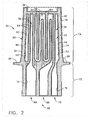
- FIG. 2 is an exemplary cross-sectional view of blade 20 including airfoil 22.
- Blade 20 includes a cooling cavity 50 defined by an internal surface 52 of blade 20.
- Cooling cavity 50 includes a plurality of inner walls 54 that separate cooling cavity 50 into a plurality of cooling chambers 56.
- inner walls 54 are cast integrally with airfoil 22.
- Cooling chambers 56 are supplied cooling air through a plurality of cooling circuits 58.
- airfoil 22 includes a forward cooling chamber 60, an aft cooling chamber 62, and a plurality of mid cooling chambers 64.
- Forward cooling chamber 60 extends longitudinally or radially through airfoil 22 to airfoil tip 38, and is bordered by airfoil first and second sidewalls 28 and 30, respectively (shown in FIG. 1), and by airfoil leading edge 32.
- Forward cooling chamber 60 is cooled with cooling air supplied by a forward cooling circuit 66, which cooling air is fed through cross-over holes (not shown) in the inner wall 54 on the trailing edge side of forward cooling chamber 60.
- Mid cooling chambers 64 are between forward cooling chamber 60 and aft cooling chamber 62, and are supplied cooling air by a mid cooling circuit 68. More specifically, mid cooling chambers 64 are in flow communication and form a serpentine cooling passageway. Mid cooling chambers 64 are bordered by airfoil first and second sidewalls 28 and 30, respectively (shown in FIG. 1), and by airfoil tip 38.
- Aft cooling chamber 62 extends longitudinally or radially through airfoil 22 to airfoil tip 38, and is bordered by airfoil first and second sidewalls 28 and 30, respectively (shown in FIG. 1), and by airfoil trailing edge 34.
- Aft cooling chamber 62 is cooled with cooling air supplied by an aft cooling circuit 70 that defines a radially outer boundary of aft cooling chamber 62.
- airfoil 22 includes a plurality of trailing edge openings (not shown) that extend between external surface 40 and internal surface 52.
- Blade 20 also includes a root portion 72 and an airfoil body portion 74.
- Root portion 72 is bounded by airfoil root 36 (shown in FIG. 1) and extends through a portion of dovetail 24 (shown in FIG. 1).
- Airfoil body portion 74 is in flow communication with root portion 72 and extends from root portion 72 to airfoil tip 38.
- portions of cooling cavity 50 extending through root portion 72 are known as root passages.
- Blade internal surface 52 is coated with a layer of an aluminide coating 76.
- the aluminide coating is applied by depositing aluminum onto the internal surface 52, so that a body of blade 20 serves as a substrate 80, by a vapor phase aluminide deposition process.
- the aluminide coating may be modified with elements such as hafnium, zirconium, yttrium, silicon, titanium, tantalum, cobalt, chromium, platinum, and palladium, and combinations thereof, to improve its corrosion resistance and other properties.
- the aluminum (and modifying elements, if any) is interdiffused with the material of the substrate 80 to form the aluminide coating 76 on the internal surface 52.
- the aluminide coating 76 has a composition with the aluminum concentration highest near the internal surface 52, and decreasing aluminum concentration with increasing distance into the substrate 80 from the internal surface 52. More specifically, the thickness of the aluminide coating 76 on internal surface 52 is less than about 0.003 inches (less than about 76.2 ⁇ m (microns)), typically from about 0.001 inches to about 0.0015 inches (from about 25.4 to about 38.1 ⁇ m (microns)), within airfoil body portion 74, and less than about 0.0015 inches (less than about 38.1 ⁇ m (microns)), typically from about 0.0005 to about 0.0015 inches (from about 12.7 to about 38.1 ⁇ m (microns)), within root portion 72, which operates at a lower temperature in comparison to airfoil body portion 74.
- the thickness of the aluminide coating 76 on internal surface 52 is less than about 0.003 inches (less than about 76.2 ⁇ m (microns)), typically from about 0.001 inches to about 0.0015 inches (from about 2
- the thickness of the aluminide coating 76 is less than about 0.001 inches (less than about 25.4 ⁇ m (microns)) within root portion 72.
- the aluminum-enriched layer at the internal surface 52 oxidizes to form an adherent aluminum oxide protective scale at the internal surface 52, inhibiting and slowing further oxidation damage.
- a layer of aluminide coating 78 is also present on the external surface 40 in the airfoil body portion 74.
- the aluminide coating is formed by depositing aluminum onto the external surface 40 in the airfoil body portion 74, so that a body of the airfoil 22 serves as a substrate 80, by a vapor phase aluminide deposition process.
- the aluminide coating may be modified with elements such as described above to improve corrosion resistance and other properties.
- the aluminum (and modifying elements, if any) is interdiffused with the material of the substrate 80 to form the aluminide coating 78 on the external surface 40.
- the aluminide coating 78 has a composition with the aluminum concentration highest near the external surface 40, and decreasing aluminum concentration with increasing distance into the substrate 80 from the external surface 40.
- the aluminide coating 78 is typically from about 0.0005 to about 0.004 inches (from about 12.7 to about 101.6 ⁇ m (microns)) thick, more typically from about 0.0015 to about 0.003 inches (from about 38.1 to about 76.2 ⁇ m (microns)) thick on external surface 40 in the airfoil body portion 74.
- the aluminum-enriched layer at the external surface 40 oxidizes to form an adherent aluminum oxide protective scale at the external surface 40, inhibiting and slowing further oxidation damage.
- An overlay protective coating may be deposited overlying and contacting the external surface 40 of the airfoil body portion 74.
- the protective coating may be of the MCrAIX type known in the art.
- the protective layer is usually from about 0.003 to about 0.007 inches (from about 76.2 to about 177.8 ⁇ m (microns)) thick, typically about 0.005 inches (about 127 ⁇ m (microns)) thick.
- the protective layer is deposited by any operable technique, such as physical vapor deposition (e.g., sputtering, cathodic arc, ion plasma, electron beam) or thermal spray.
- the overall protective coating optionally includes a ceramic layer deposited overlying and contacting the protective layer.
- the ceramic layer is usually from about 0.003 to about 0.010 inches (from about 76.2 to about 254 ⁇ m (microns)) thick, typically about 0.005 inches (about 127 ⁇ m (microns)) thick.
- the ceramic layer is usually yttria-stabilized zirconia, which is zirconium oxide comprising from about 2 to about 12 weight percent, typically from about 3 to about 8 weight percent, yttrium oxide. It may be deposited by any operable technique, such as physical vapor deposition or thermal spray. Other operable ceramic materials may be used as well.
- cooling air is supplied into airfoil 22 through cooling circuits 58.
- cooling air is supplied into airfoil 22 from a compressor. Cooling air entering root portion 72 is channeled into cooling chambers 56 and airfoil body portion 74. Because hot combustion gases impinge upon airfoil body portion 74, the operating temperature of airfoil body portion 74 typically increases to a higher temperature than that associated with root portion 72.
- the aluminide coating facilitates reducing oxidation of external surface 40 and internal surface 52 in the airfoil body portion 74 despite the increased operating temperature.
- root portion 72 stresses generated during engine operation may be induced into root portion 72.
- Limiting the thickness of the aluminide coating to less than about 0.0015 inches (about 38.1 ⁇ m (microns)) on internal surface 52 within root portion 72 facilitates preventing material degradation and cracking within root portion 72, thereby maintaining the fatigue life of blade 20. More specifically, limiting cracking of the aluminide coating within root portion 72 facilitates maintaining fatigue life within root portion 72, and thus extends the useful life of blade 20.
- FIG. 3 illustrates a typical vapor coating apparatus useful for applying an aluminide coating to gas turbine engine blades such as shown in FIG. 1.
- the vapor coating apparatus is indicated generally as 100, and includes a generally cylindrical coating container indicated as 110.
- a gas distributor 112 (including a pipe 116 for receiving inert gas from a source of supply, and a manifold 118) is sized to fit within container 110.
- Container 110 has a top or lid indicated as 114, a base indicated as 120 spaced from lid 114, and a generally cylindrical circumferential side wall indicated as 122 that connects lid 114 and base 120 and extends downwardly beyond base 120. Lid 114, base 120 and side wall 122 of container 110 define an interior coating chamber indicated as 124.
- pipe 116 of distributor 112 is inserted partially through a hole or aperture 126 at or proximate to the center of lid 114.
- Manifold 118 is positioned within chamber 124 at or proximate to the top thereof, i.e., proximate to lid 114.
- Apparatus 100 also has an article support or holder 128 attached to or otherwise associated with base 120 of container 110 that is provided with apertures, typically in the form of slots (not shown) or other suitable devices, for receiving and holding the turbine blades 132 to be coated. Prior to coating blades 132 with the aluminide coating, it may be desirable to mask those areas not requiring any coating. For example, all or part of the external surface in the root portion of the blade may be masked. Apparatus 100 also has holders in the form of perforated baskets indicated as 140 positioned within container 110 for receiving or holding pellets of the aluminum coating source material. As shown in FIG. 3, baskets 140 and blades 132 are below manifold 118 of distributor 112.
- the number and spacing of baskets 140 and blades 132 can be varied depending upon the internal dimensions and configuration of container 110, the size of blades 132 to be coated and like factors known to those skilled in the art.
- the blades 132 and baskets 140 may be arranged in alternating concentric rows or circles.
- the spacing of the blades 132 and baskets 140 should be such as to allow the free flow of gas therebetween.
- a powdered halide activator indicated generally as 146. This powdered halide activator is typically placed so as not to touch or be in contact with blades 132 or baskets 140.
- Pipe 116 typically is then connected to a source of a nonoxidizing or inert carrier gas such as hydrogen, nitrogen, helium, or argon.
- the loaded coating container 110 is then heated to a temperature in the range of from about 1000 to about 1125°C (from about 1832 to about 2057°F), typically from about 1050 to about 1110°C (from about 1922 to about 2030°F), more typically from about 1065 to about 1100°C (about 1949 to about 2012°F).
- the loaded coating chamber is maintained within the above temperature range for a period of time ranging from about 0.5 to about 4 hours, typically from about 1 to about 3 hours, more typically from about 1.5 to about 2.5 hours.
- the particular elevated temperature and time selected will depend on the coating application parameters desired (including the source of aluminide coating used) and other factors that would be understood by those skilled in the art.
- the powdered activator 146 will form a reactive halide gas.
- Suitable halide activators can be selected from aluminum chloride, aluminum fluoride, aluminum bromide, ammonium chloride, ammonium fluoride, ammonium bromide, and mixtures thereof.
- Hydrogen chloride (a gas in its standard state) may also be used as the halide activator herein.
- the reactive halide gas flows through the pellets in baskets 140 comprising the aluminide coating source (e.g., aluminum source) and reacts with the aluminum source to provide the aluminide coating gas, typically in the form of an aluminum halide gas.
- the aluminum source can be any aluminum or aluminum alloy, for example, cobalt aluminum alloys (CoAl), iron aluminum alloys (FeAl), or chromium aluminum alloys (CrAl), typically in powder or pelletized form.
- the reactive halide gas may be flowed into the loaded coating container through one or more pipes (such as pipe 116), instead of being generated within the coating container as described above.
- the aluminide coating gas may be generated in a reactor external to the coating container, and then flowed into the loaded coating container through one or more pipes.
- the reaction kinetics controlling the rate of formation of the aluminide coating gas will be dependent on the temperature, as well as the rate at which any carrier gas is introduced into chamber 124 by distributor 112, which is the driving force for moving the aluminide coating gas within chamber 124, as well as amongst, around and through blades 132.
- the aluminide coating on the external surface of blades 132 typically has a thickness of from about 0.0005 to about 0.004 inches (from about 12.7 to about 101.6 ⁇ m (microns)), more typically from about 0.0015 to about 0.003 inches (from about 38.1 to about 76.2 ⁇ m (microns)).
- the rate and uniformity of deposition is influenced by the uniformity of the aluminide coating gas environment in proximity to blades 132, as previously discussed.
- static coating techniques in which no inert carrier gas is introduced into coating chamber 124, are used to deposit an aluminide coating on the external surface of blades 132.
- an inert carrier gas may be introduced into coating chamber 124 through pipe 116 at a relatively low gas flow rate, for example, less than about 20 ft. 3 /hour (about 566 liters/hour), typically less than about 15 ft. 3 /hour (about 425 liters/hour), more typically less than about 10 ft. 3 /hour (about 283 liters/hour).
- interior chamber 124 is purged of air by introducing the nonoxidizing or inert carrier gas, such as argon or hydrogen, through pipe 116.
- This carrier gas then flows into manifold 118, which has a configuration similar to a "shower head” in that it comprises a plurality of gas outlet holes (not shown) spaced along the periphery of a cylindrical or disk-shaped head.
- the carrier gas exits through the outlet holes as gas streams 150 so as to provide an inert gas atmosphere.
- the rate at which the carrier gas flows into pipe 116 (and out of the outlet holes as gas streams 150) of manifold 118 is in the range of from about 20 to about 150 ft.
- each gas stream 150 is directed in a downward path so that the inert carrier gas swirls above the concentric rows of baskets 140 and blades 132, thus creating a relatively uniform and homogeneous atmosphere in chamber 124.
- the pressure of the gas flow forces the streams 150 of the carrier gas downwardly from distributor 112 and around and through the rows of baskets 140 and blades 132.
- the carrier gas applies a certain minimum pressure. This is typically achieved by having the carrier gas continue to flow into chamber 124 at the previously indicated flow rates through pipe 116.
- the carrier gas can be used to control the uniformity of the aluminide coating gas environment, and hence reduction of the aluminide coating gas at the surface (exterior and interior), and to provide the necessary pressure to move and force the aluminide coating gas through the rows of blades 132 and into the interior of blades 132, thereby coating them.
- the inert carrier gas commingles and mixes with the aluminide coating gas and acts to aid in the coating of external and internal surfaces of blades 132.
- the inert carrier gas is flowed into the loaded coating chamber at the above rates for a period of time ranging from about 0.5 to about 4 hours, typically from about 1 to about 3 hours, more typically from about 1.5 to about 2.5 hours, to move the aluminide coating gas through the cooling holes and the internal cooling cavity of the blades, while maintaining the loaded coating chamber at a temperature within the about 1000 to about 1125°C, to deposit an aluminide coating on the internal surface of the blades.
- the aluminide coating on the internal surface of the blades 132 has a thickness of less than about 0.003 inches (less than about 76.2 ⁇ m (microns)), typically from about 0.0005 to about 0.0015 inches (from about 12.7 to about 38.1 ⁇ m (microns)).
- the remaining aluminide coating gas is exhausted from chamber 124 through gas exhaust outlet indicated as 152 and into an open evacuation chamber or area indicated as 160 defined by the extension of side wall 122 beyond base 120.
- container 110 can be removed from the furnace and cooled or optionally furnace cooled, while maintaining an inert gas atmosphere if desired.
- test blades were high-pressure gas turbine engine blades made from a single crystal nickel-based superalloy, designated by the trade name René® N5.
- the blades had an external surface and an internal cooling cavity defined by an internal surface connected to the external surface by cooling holes in the airfoil body portion of the blade.
- a two-step process different from the present invention was used to apply an aluminide coating to sample blades in the coating container shown in FIG. 3.
- argon gas was flowed into the coating container to force aluminide coating vapors, formed by reacting aluminum fluoride activator with chromium aluminum alloy pellets as described regarding FIG. 3, to flow through the cooling holes and internal cooling cavities of the blades and out of the dovetail root holes of the blades.
- aluminide coating was deposited on internal surfaces of the blades. The thickness of the internal coating and the aluminum content were controlled by the temperature, gas flow, elapsed time of gas flow, and amount of activator in the coating container.
- the argon gas flow to the coating container was stopped, creating a static environment that primarily affected the external portions of the blades and resulted in the deposition of an aluminide coating on their internal surfaces.
- the thickness of the external coating and the aluminum content were controlled by the temperature, the dwell time at the temperature, and the amount of activator remaining in the coating container after the first step.
- the two-step process used 70 grams of aluminum fluoride activator, a coating temperature of about 1975°F (about 1079°C) during both steps, argon gas flowing at 120 ft. 3 /hour (about 3398 liters/hour) for 1 hour during first step, and 5 hours of static dwell during the second step.
- the aluminide coating deposited on the external surfaces in the airfoil body portion of the blades had a thickness of about 0.002-0.0025 inches (about 50.8-63.5 ⁇ m (microns)).
- the internal surfaces of the other airfoil body cavities and dovetail cavities were bare.
- Sample blades were coated in the coating container shown in FIG. 3 using a method of the invention.
- the order of the reverse flow and static steps of Example 1 was reversed, and coating parameters were altered to deposit a thin, controlled aluminide coating having a thickness of less than 0.0015 inches (about 38.1 ⁇ m (microns)) on the internal surfaces of all airfoil and dovetail cavities of the blades.
- Switching of the reverse flow and static steps allowed the formation of the external coating and internal coating to be more independent of each other.
- the first static step formed the external coating without significantly affecting the internal coating because there was no gas flowing into the coating container.
- argon gas flow was introduced into the container to deposit the internal coating with little influence on the external coating since most of the coating vapors were forced into and exhausted out of the blades.
- the internal coating thickness and the aluminum content were controlled by the amount of gas flow, the elapsed time of flow, and the temperature.
- This two-step process used 250 grams of aluminum fluoride activator, a coating temperature of about 1975°F (about 1079°C) during both steps, 2 hours of static dwell during the first step, and argon gas flowing at 90 ft. 3 /hour (about 2549 liters/hour) for 2 hours during the second step.
- the aluminide coating deposited on the external surfaces in the airfoil body portion of the blades had a thickness of about 0.002-0.0025 inches (about 50.8-63.5 ⁇ m (microns)).
- An aluminide coating having a thickness of from about 0.001-0.0015 inches (about 25.4-38.1 ⁇ m (microns)) was also formed on the internal airfoil body surfaces of the blades.
- An aluminide coating having a thickness of from about 0.0005-0.0015 inches (about 12.7-38.1 ⁇ m (microns)) was also formed on the internal surfaces of the dovetail cavities (i.e., the root portions) of the blades.
Landscapes
- Chemical & Material Sciences (AREA)
- Engineering & Computer Science (AREA)
- Materials Engineering (AREA)
- Mechanical Engineering (AREA)
- Chemical Kinetics & Catalysis (AREA)
- Metallurgy (AREA)
- Organic Chemistry (AREA)
- General Engineering & Computer Science (AREA)
- Turbine Rotor Nozzle Sealing (AREA)
Claims (10)
- Verfahren zum Aufbringen einer Aluminidbeschichtung (76, 78) auf eine Schaufel (20, 132) eines Gasturbinentriebwerks, die eine Außenfläche (40) und eine innere Kühlausnehmung (50) aufweist, die durch eine Innenfläche (52) definiert ist, die über Kühllöcher (42) mit der Außenfläche (40) verbunden ist, wobei das Verfahren in einem Dampfbeschichtungsbehälter (110) durchgeführt wird, der eine hohle innere Beschichtungskammer (124) aufweist, wobei das Verfahren die Schritte enthält:(a) Beschicken der Beschichtungskammer (124) mit der zu beschichtenden Schaufel (20, 132),(b) Bereitstellen eines Aluminidbeschichtungsgases in der beschickten Beschichtungskammer (124),(c) Aufrechterhalten einer Temperatur von 1000°C bis 1125°C in der beschickten Beschichtungskammer (124), die das Aluminidbeschichtungsgas enthält, für 0,5 bis 4 Stunden zur Ablagerung einer Aluminidbeschichtung (78) auf der Außenseite (40) der Schaufel (20, 132) und dann(d) Einleiten eines inerten Trägergases (150), das das Aluminidbeschichtungsgas enthält, in die beschickte Beschichtungskammer (124) mit einer Flussrate von 20 bis 150 Kubikfuß pro Stunde (566 bis 4.248 Liter/Stunde) für 0,5 bis 4 Stunden, um das Aluminidbeschichtungsgas durch die Kühlöffnungen (42) und die innere Kühlausnehmung (50) der Schaufel (20, 132) zu schaffen, während die beschickte Beschichtungskammer (124) bei einer Temperatur von 1000°C bis 1125°C gehalten wird, um auf der Innenfläche (42) der Schaufel (20, 132) eine Aluminidbeschichtung (76) abzulagern.
- Verfahren nach Anspruch 1 mit dem weiteren Schritt des Beschickens der Beschichtungskammer (124) mit einer Aluminiumquelle, die das Aluminidbeschichtungsgas des Schritts (b) in der Beschichtungskammer (124) erzeugt.
- Verfahren nach Anspruch 1 oder 2, bei dem das Aluminidbeschichtungsgas durch Reaktion einer Aluminiumquelle mit einem Halogenaktivator (146) gebildet wird.
- Verfahren nach Anspruch 3, bei dem der Halogenaktivator (146) aus einer Gruppe ausgewählt ist, zu der Aluminiumchlorid, Aluminiumfluorid, Aluminiumbromid, Ammoniumchlorid, Ammoniumfluorid, Ammoniumbromid, Chlorwasserstoff und Mischungen derselben, gehören.
- Verfahren nach einem der vorausgehenden Ansprüche, bei dem in Schritt (c) die beschickte, das Aluminiumbeschichtungsgas enthaltende Beschichtungskammer (124) für 1 bis 3 Stunden bei einer Temperatur von 1050°C bis 1110°C, vorzugsweise von 1065°C bis 1100°C gehalten wird.
- Verfahren nach einem der vorausgehenden Ansprüche, bei dem die Gasflussrate in Schritt (d) in dem Bereich von 60 bis 120 Kubikfuß pro Stunde (1699 bis 3398 Liter/Stunde), vorzugsweise von 80 bis 100 Kubikfuß pro Stunde (2265 bis 2832 Liter/Stunde) beträgt.
- Verfahren nach einem der vorhergehenden Ansprüche, bei dem das Trägergas (150) Argon oder Wasserstoff ist.
- Verfahren nach einem der vorausgehenden Ansprüche, bei dem die Temperatur in Schritt (d) von 1050°C bis 1110°C, vorzugsweise von 1065°C bis 1100°C beträgt.
- Verfahren nach einem der vorausgehenden Ansprüche, bei dem die Aluminidbeschichtung (76) an der Innenfläche in dem Schaufelkörperabschnitt (74) der Schaufel (20, 132) weniger als 0,003 Zoll (weniger als 76,2 µm (Mikron)) dick und in den Fußabschnitt (72) weniger als 0,0015 Zoll (weniger als 38,1 µm (Mikron)) dick ist.
- Verfahren nach einem der vorausgehenden Ansprüche, bei dem die Aluminidbeschichtung (78) an der Außenseite (40) der Schaufel (20, 132) in dem Schaufelkörperabschnitt (74) an der Außenseite (40) der Schaufel (20, 132) von 0,0015 bis 0,003 Zoll (von 38,1 bis 76,2 µm (Mikron)) dick ist.
Priority Applications (1)
| Application Number | Priority Date | Filing Date | Title |
|---|---|---|---|
| DE602004000818.4T DE602004000818T3 (de) | 2003-02-04 | 2004-02-04 | Beschichtung aus Aluminid für Gasturbinenschaufel |
Applications Claiming Priority (2)
| Application Number | Priority Date | Filing Date | Title |
|---|---|---|---|
| US10/357,972 US7026011B2 (en) | 2003-02-04 | 2003-02-04 | Aluminide coating of gas turbine engine blade |
| US357972 | 2003-02-04 |
Publications (3)
| Publication Number | Publication Date |
|---|---|
| EP1445346A1 EP1445346A1 (de) | 2004-08-11 |
| EP1445346B1 true EP1445346B1 (de) | 2006-05-10 |
| EP1445346B2 EP1445346B2 (de) | 2013-08-07 |
Family
ID=32655624
Family Applications (1)
| Application Number | Title | Priority Date | Filing Date |
|---|---|---|---|
| EP04250585.9A Expired - Fee Related EP1445346B2 (de) | 2003-02-04 | 2004-02-04 | Beschichtung aus Aluminid für Gasturbinenschaufel |
Country Status (4)
| Country | Link |
|---|---|
| US (1) | US7026011B2 (de) |
| EP (1) | EP1445346B2 (de) |
| DE (1) | DE602004000818T3 (de) |
| SG (1) | SG120972A1 (de) |
Families Citing this family (15)
| Publication number | Priority date | Publication date | Assignee | Title |
|---|---|---|---|---|
| US7700154B2 (en) * | 2005-11-22 | 2010-04-20 | United Technologies Corporation | Selective aluminide coating process |
| US20070190245A1 (en) * | 2006-02-15 | 2007-08-16 | General Electric Company | Method of coating gas turbine components |
| KR100702257B1 (ko) | 2006-03-02 | 2007-04-03 | 허민 | 스크루 펌프의 회전날개 제조방법 |
| US20080232424A1 (en) * | 2007-03-23 | 2008-09-25 | Honeywell International Inc. | Hearth plate including side walls defining a processing volume |
| FR2921939B1 (fr) * | 2007-10-03 | 2009-12-04 | Snecma | Procede d'aluminisation en phase vapeur sur pieces metalliques creuses de turbomachine |
| US8545185B2 (en) * | 2007-12-19 | 2013-10-01 | General Electric Company | Turbine engine components with environmental protection for interior passages |
| FR2992977B1 (fr) | 2012-07-03 | 2017-03-10 | Snecma | Procede et outillage pour le depot d'un revetement metallique en phase vapeur sur des pieces en super alliages |
| CA2882788C (en) | 2014-02-26 | 2019-01-22 | Endurance Technologies, Inc. | Coating compositions, methods and articles produced thereby |
| US9909202B2 (en) * | 2014-05-02 | 2018-03-06 | General Electric Company | Apparatus and methods for slurry aluminide coating repair |
| US9844799B2 (en) | 2015-12-16 | 2017-12-19 | General Electric Company | Coating methods |
| FR3047255B1 (fr) * | 2016-01-28 | 2018-01-12 | Snecma Mexico, S.A. De C.V. | Outillage pour la mise en oeuvre d'un procede de depot d'un revetement metallique en phase vapeur sur des pieces de turbomachine |
| US11383910B2 (en) | 2017-09-13 | 2022-07-12 | Liqui-Box Corporation | Process for preventing organoleptic degradation in flexibly-packaged sensitive foods and packaged products thereof |
| US20190284941A1 (en) | 2018-03-16 | 2019-09-19 | United Technologies Corporation | Location-specific slurry based coatings for internally-cooled component and process therefor |
| DE102018221579A1 (de) * | 2018-12-13 | 2020-06-18 | MTU Aero Engines AG | Vorrichtung und Verfahren zum Gasphasenbeschichten von Werkstücken |
| CN112430802B (zh) * | 2020-10-09 | 2022-02-08 | 北京航空航天大学 | 复杂内腔叶片氟离子清洗及铝化物涂层制备的方法及装置 |
Family Cites Families (33)
| Publication number | Priority date | Publication date | Assignee | Title |
|---|---|---|---|---|
| FR1433497A (fr) † | 1965-02-16 | 1966-04-01 | Snecma | Procédé de dépôt d'une couche protectrice sur une pièce métallique par une méthode en phase vapeur |
| US4132816A (en) | 1976-02-25 | 1979-01-02 | United Technologies Corporation | Gas phase deposition of aluminum using a complex aluminum halide of an alkali metal or an alkaline earth metal as an activator |
| US4332843A (en) | 1981-03-23 | 1982-06-01 | General Electric Company | Metallic internal coating method |
| US4714624A (en) | 1986-02-21 | 1987-12-22 | Textron/Avco Corp. | High temperature oxidation/corrosion resistant coatings |
| US5071678A (en) | 1990-10-09 | 1991-12-10 | United Technologies Corporation | Process for applying gas phase diffusion aluminide coatings |
| DE4119967C1 (de) † | 1991-06-18 | 1992-09-17 | Mtu Muenchen Gmbh | |
| US5221354A (en) | 1991-11-04 | 1993-06-22 | General Electric Company | Apparatus and method for gas phase coating of hollow articles |
| US5264245A (en) | 1991-12-04 | 1993-11-23 | Howmet Corporation | CVD method for forming uniform coatings |
| US5261963A (en) | 1991-12-04 | 1993-11-16 | Howmet Corporation | CVD apparatus comprising exhaust gas condensation means |
| EP0731187A1 (de) | 1995-03-07 | 1996-09-11 | Turbine Components Corporation | Verfahren zur Erzeugung einer Schutzdiffusionsschicht auf Legierungen auf Nickel-, Kobalt- und Eisenbasis |
| DE19607625C1 (de) † | 1996-02-29 | 1996-12-12 | Mtu Muenchen Gmbh | Vorrichtung und Verfahren zur Präparation und/oder Beschichtung der Oberflächen von Hohlbauteilen |
| US5910219A (en) | 1997-06-06 | 1999-06-08 | United Technologies Corporation | Can coating system |
| US5928725A (en) | 1997-07-18 | 1999-07-27 | Chromalloy Gas Turbine Corporation | Method and apparatus for gas phase coating complex internal surfaces of hollow articles |
| DE19803740C2 (de) | 1998-01-30 | 2001-05-31 | Mtu Aero Engines Gmbh | Gasphasenbeschichtungsverfahren und Vorrichtung zur Gasphasenbeschichtung von Werkstücken |
| JPH11230212A (ja) * | 1998-02-10 | 1999-08-27 | Akebono Brake Ind Co Ltd | エアディスクブレーキ |
| US6110262A (en) | 1998-08-31 | 2000-08-29 | Sermatech International, Inc. | Slurry compositions for diffusion coatings |
| US6039810A (en) | 1998-11-13 | 2000-03-21 | General Electric Company | High temperature vapor coating container |
| US6224941B1 (en) * | 1998-12-22 | 2001-05-01 | General Electric Company | Pulsed-vapor phase aluminide process for high temperature oxidation-resistant coating applications |
| US6334907B1 (en) † | 1999-06-30 | 2002-01-01 | General Electric Company | Method of controlling thickness and aluminum content of a diffusion aluminide coating |
| US6254756B1 (en) | 1999-08-11 | 2001-07-03 | General Electric Company | Preparation of components having a partial platinum coating thereon |
| US6273678B1 (en) * | 1999-08-11 | 2001-08-14 | General Electric Company | Modified diffusion aluminide coating for internal surfaces of gas turbine components |
| US6283714B1 (en) | 1999-08-11 | 2001-09-04 | General Electric Company | Protection of internal and external surfaces of gas turbine airfoils |
| US6332926B1 (en) | 1999-08-11 | 2001-12-25 | General Electric Company | Apparatus and method for selectively coating internal and external surfaces of an airfoil |
| US6296447B1 (en) | 1999-08-11 | 2001-10-02 | General Electric Company | Gas turbine component having location-dependent protective coatings thereon |
| US6383306B1 (en) | 2000-02-28 | 2002-05-07 | General Electric Company | Preparation of a nickel-base superalloy article having a decarburized coating containing aluminum and a reactive element |
| US6589668B1 (en) | 2000-06-21 | 2003-07-08 | Howmet Research Corporation | Graded platinum diffusion aluminide coating |
| US6497920B1 (en) | 2000-09-06 | 2002-12-24 | General Electric Company | Process for applying an aluminum-containing coating using an inorganic slurry mix |
| US6434876B1 (en) | 2000-09-26 | 2002-08-20 | General Electric Company | Method of applying a particle-embedded coating to a substrate |
| US6533875B1 (en) | 2000-10-20 | 2003-03-18 | General Electric Co. | Protecting a surface of a nickel-based article with a corrosion-resistant aluminum-alloy layer |
| DE10101070C1 (de) † | 2001-01-11 | 2002-10-02 | Mtu Aero Engines Gmbh | Verfahren zum Gasphasendiffusionsbeschichten von metallischen Bauteilen |
| US6485262B1 (en) | 2001-07-06 | 2002-11-26 | General Electric Company | Methods and apparatus for extending gas turbine engine airfoils useful life |
| US6881439B2 (en) * | 2002-12-04 | 2005-04-19 | General Electric Company | Aluminide coating process |
| US6929825B2 (en) * | 2003-02-04 | 2005-08-16 | General Electric Company | Method for aluminide coating of gas turbine engine blade |
-
2003
- 2003-02-04 US US10/357,972 patent/US7026011B2/en not_active Expired - Fee Related
-
2004
- 2004-01-28 SG SG200400369A patent/SG120972A1/en unknown
- 2004-02-04 DE DE602004000818.4T patent/DE602004000818T3/de not_active Expired - Lifetime
- 2004-02-04 EP EP04250585.9A patent/EP1445346B2/de not_active Expired - Fee Related
Also Published As
| Publication number | Publication date |
|---|---|
| SG120972A1 (en) | 2006-04-26 |
| DE602004000818T2 (de) | 2006-12-21 |
| EP1445346B2 (de) | 2013-08-07 |
| US7026011B2 (en) | 2006-04-11 |
| US20040151834A1 (en) | 2004-08-05 |
| EP1445346A1 (de) | 2004-08-11 |
| DE602004000818D1 (de) | 2006-06-14 |
| DE602004000818T3 (de) | 2014-01-02 |
Similar Documents
| Publication | Publication Date | Title |
|---|---|---|
| EP1445345B1 (de) | Beschichtung aus Aluminid für Gasturbinenschaufel | |
| EP1079073B1 (de) | Diffusionsbeschichtung aus modifiziertem Aluminid für die Innenfläche von Gasturbinenbauteilen | |
| US6905730B2 (en) | Aluminide coating of turbine engine component | |
| EP1209247B1 (de) | CVD Aluminisierungsverfahren zur Herstellung einer modifizierten Platin-Aluminidbeschichtung für verbesserte Hochtemperaturleistung | |
| US6440496B1 (en) | Method of forming a diffusion aluminide coating | |
| US6332926B1 (en) | Apparatus and method for selectively coating internal and external surfaces of an airfoil | |
| EP0844368B2 (de) | Teilbeschichtung von Gasturbinenschaufeln zur Erhöhung der Dauerfestigkeit | |
| EP1790753B1 (de) | Duplex Gasbeschichten | |
| EP1445346B1 (de) | Beschichtung aus Aluminid für Gasturbinenschaufel | |
| JP5997432B2 (ja) | 構成部品、ならびに、構成部品の製造および被覆方法 | |
| EP0987347B1 (de) | Wärmedämmschicht-System und Verfahren dazu | |
| EP0897996B1 (de) | Aluminid/MCrAlY Beschichtungssystem | |
| EP0979881B1 (de) | Wärmedämmendes Beschichtungssystem und Überzug mit einer Metall/Metalloxyd-Haftbeschichtigung | |
| EP0886685B1 (de) | Verbesserte wärmeschutz-beschichtung und verfahren zu ihrer herstellung | |
| EP1927672B1 (de) | Diffusionsaluminidbeschichtungsvorgang | |
| JPS6339663B2 (de) | ||
| EP1895019B1 (de) | Verfahren und Vorrichtung zur Steuerung der Diffusionsbeschichtung interner Bereiche | |
| EP3470543A1 (de) | Beschichtetes bauteil und verfahren zur herstellung eines beschichteten bauteils |
Legal Events
| Date | Code | Title | Description |
|---|---|---|---|
| PUAI | Public reference made under article 153(3) epc to a published international application that has entered the european phase |
Free format text: ORIGINAL CODE: 0009012 |
|
| AK | Designated contracting states |
Kind code of ref document: A1 Designated state(s): AT BE BG CH CY CZ DE DK EE ES FI FR GB GR HU IE IT LI LU MC NL PT RO SE SI SK TR |
|
| AX | Request for extension of the european patent |
Extension state: AL LT LV MK |
|
| 17P | Request for examination filed |
Effective date: 20050211 |
|
| AKX | Designation fees paid |
Designated state(s): DE FR GB |
|
| RBV | Designated contracting states (corrected) |
Designated state(s): DE FR GB |
|
| GRAP | Despatch of communication of intention to grant a patent |
Free format text: ORIGINAL CODE: EPIDOSNIGR1 |
|
| GRAS | Grant fee paid |
Free format text: ORIGINAL CODE: EPIDOSNIGR3 |
|
| GRAA | (expected) grant |
Free format text: ORIGINAL CODE: 0009210 |
|
| AK | Designated contracting states |
Kind code of ref document: B1 Designated state(s): DE FR GB |
|
| REG | Reference to a national code |
Ref country code: GB Ref legal event code: FG4D |
|
| REF | Corresponds to: |
Ref document number: 602004000818 Country of ref document: DE Date of ref document: 20060614 Kind code of ref document: P |
|
| ET | Fr: translation filed | ||
| PLBI | Opposition filed |
Free format text: ORIGINAL CODE: 0009260 |
|
| PLAX | Notice of opposition and request to file observation + time limit sent |
Free format text: ORIGINAL CODE: EPIDOSNOBS2 |
|
| 26 | Opposition filed |
Opponent name: MTU AERO ENGINES GMBH Effective date: 20070212 |
|
| PLAF | Information modified related to communication of a notice of opposition and request to file observations + time limit |
Free format text: ORIGINAL CODE: EPIDOSCOBS2 |
|
| PLBB | Reply of patent proprietor to notice(s) of opposition received |
Free format text: ORIGINAL CODE: EPIDOSNOBS3 |
|
| PLBP | Opposition withdrawn |
Free format text: ORIGINAL CODE: 0009264 |
|
| PGFP | Annual fee paid to national office [announced via postgrant information from national office to epo] |
Ref country code: FR Payment date: 20130311 Year of fee payment: 10 Ref country code: DE Payment date: 20130227 Year of fee payment: 10 Ref country code: GB Payment date: 20130227 Year of fee payment: 10 |
|
| PUAH | Patent maintained in amended form |
Free format text: ORIGINAL CODE: 0009272 |
|
| STAA | Information on the status of an ep patent application or granted ep patent |
Free format text: STATUS: PATENT MAINTAINED AS AMENDED |
|
| 27A | Patent maintained in amended form |
Effective date: 20130807 |
|
| AK | Designated contracting states |
Kind code of ref document: B2 Designated state(s): DE FR GB |
|
| REG | Reference to a national code |
Ref country code: DE Ref legal event code: R102 Ref document number: 602004000818 Country of ref document: DE Effective date: 20130807 |
|
| REG | Reference to a national code |
Ref country code: DE Ref legal event code: R119 Ref document number: 602004000818 Country of ref document: DE |
|
| GBPC | Gb: european patent ceased through non-payment of renewal fee |
Effective date: 20140204 |
|
| REG | Reference to a national code |
Ref country code: FR Ref legal event code: ST Effective date: 20141031 |
|
| REG | Reference to a national code |
Ref country code: DE Ref legal event code: R119 Ref document number: 602004000818 Country of ref document: DE Effective date: 20140902 |
|
| PG25 | Lapsed in a contracting state [announced via postgrant information from national office to epo] |
Ref country code: DE Free format text: LAPSE BECAUSE OF NON-PAYMENT OF DUE FEES Effective date: 20140902 Ref country code: GB Free format text: LAPSE BECAUSE OF NON-PAYMENT OF DUE FEES Effective date: 20140204 Ref country code: FR Free format text: LAPSE BECAUSE OF NON-PAYMENT OF DUE FEES Effective date: 20140228 |