EP1445175A2 - Torsionelastisch Rahmen, insbesondere für den Einsatz in Fahrzeugen von Antriebseinheiten - Google Patents
Torsionelastisch Rahmen, insbesondere für den Einsatz in Fahrzeugen von Antriebseinheiten Download PDFInfo
- Publication number
- EP1445175A2 EP1445175A2 EP04000213A EP04000213A EP1445175A2 EP 1445175 A2 EP1445175 A2 EP 1445175A2 EP 04000213 A EP04000213 A EP 04000213A EP 04000213 A EP04000213 A EP 04000213A EP 1445175 A2 EP1445175 A2 EP 1445175A2
- Authority
- EP
- European Patent Office
- Prior art keywords
- frame
- cross member
- longitudinal
- main
- secondary cross
- Prior art date
- Legal status (The legal status is an assumption and is not a legal conclusion. Google has not performed a legal analysis and makes no representation as to the accuracy of the status listed.)
- Granted
Links
Images

Classifications
-
- B—PERFORMING OPERATIONS; TRANSPORTING
- B62—LAND VEHICLES FOR TRAVELLING OTHERWISE THAN ON RAILS
- B62D—MOTOR VEHICLES; TRAILERS
- B62D21/00—Understructures, i.e. chassis frame on which a vehicle body may be mounted
- B62D21/11—Understructures, i.e. chassis frame on which a vehicle body may be mounted with resilient means for suspension, e.g. of wheels or engine; sub-frames for mounting engine or suspensions
Definitions
- the invention relates to a frame, in detail with the features from Preamble of claim 1.
- Drive units for use in vehicles, in particular Rail vehicles are known in a variety of designs. This comprise at least one drive machine and possibly one with it coupled gear unit as well as other ancillary units, which thereby in specially designed frame units are articulated.
- the variety of types and Design of the drive components, their arrangement and the spatial Conditions of the individual vehicle, especially when used in Rail vehicles of the individual railcar type require a high level Variety of variants that are also designed with regard to resilience.
- From the Document DE 100 61 127 A1 discloses a frame series in which the single frame consists of a main and a secondary cross member, which over a longitudinal member are connected to each other.
- the frame is flexible and Torsionally elastic. This offers the possibility of an optimal recording and initiation of forces.
- connection of the side members takes place stiffly on the cross beams. Deformations of the frame, especially the Side members are prevented by the rigid connections, which means that Overall system is exposed to high voltages, which when designing the Framework must be taken into account. However, these burdens are not always definable.
- the invention is therefore based on the object, a framework of the beginning to further develop the type mentioned in such a way that the disadvantages mentioned are avoided become.
- an optimal introduction of the engine-gear unit due to the longitudinal load in the main cross member, also a load due to the twisting or bending of the Car body does not lead to undefined loads in the frame structure should.
- the drive unit is better to decouple from the environment in order to do this To keep noise behavior as low as possible during operation.
- the frame comprises a main frame, the main frame in Mainly serves to link to a chassis or car body.
- the main frame comprises at least one main cross member for receiving and transmission of the main load in all directions, a secondary cross member Recording the supporting forces of the drive unit, in particular a motor-gear unit as well as the majority of the mass forces from auxiliary or Additional units and one between the main and secondary cross members in Longitudinal truss.
- This serves as the connection between the main cross and secondary cross beams and realizes an arrangement and Assembly level for the main mass, especially a motor-gear unit and possibly an arrangement and assembly level for auxiliary units, each offset in the vertical direction to the main cross member and / or secondary cross member are arranged.
- connection of the side member with the Secondary cross members are made with low rigidity or an adapted Stiffness jump related to the bending stiffness of the side member. It's going on no rigid connection of the side member to the secondary cross member.
- Main crossmember and secondary crossmember can be made according to the circumstances in a vertical plane or in a vertical plane Plane arranged offset to one another. At least is, however, an offset between the side member and the secondary cross member intended. This is via support beams and their coupling with the Compensated side members and / or the secondary cross member.
- To realize the Soft design of the side member is at least indirectly elastic connected to the secondary girders via the support girders. This can be done through the special design of the connection between the longitudinal beam and the support beam take place, the coupling between the support beam and secondary cross beam is rigid. This configuration can be done by the two Fasteners are made or by special intermediate elements.
- a another possibility is the coupling between the support beam and To design the longitudinal beams to be rigid, the connection of the support beams to the Secondary cross member then takes place elastically.
- the side member or the individual side member elements are defined curved, so that a connection to the main cross member preferably directly in a plane which is determined by the main cross member, can be done.
- the connection to the secondary cross member is made indirectly via Support beams.
- the side member is thus characterized by a bend, the one Connection directly to the main crossmember enables, the course in Longitudinal direction to the secondary cross member through a course in the vertical direction considered characterized downwards. According to the dimensioning of the Bending the side member, the elasticity of which can be adjusted in the consequence of which are the main loads on the main cross member and the low loads be transferred to the secondary cross member.
- the frame may also include a separate subframe to accommodate the drive unit and support it on the main frame. This is hinged to the main frame and serves to support the main mass, especially a motor-gear unit on the frame.
- the subframe is in in this case releasably connectable to the main frame.
- Another possibility consists of the main mass not specifically over a subframe, but directly in the intended arrangement and assembly level on To link or store the main frame.
- the solution according to the invention is in particular for supporting and storing Drive components suitable.
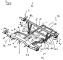
- FIG. 1 illustrates in a schematically simplified representation the basic structure of a frame 1 designed according to the invention in a flexible and torsionally elastic design, which is particularly advantageously suitable for use in rail vehicles, regardless of the type of drive system, for example railcars with diesel-hydraulic drive systems.
- the frame 1 comprises a main frame 2, which is composed of longitudinal members and cross members, and a subframe 3, which can be assigned to the main frame 2 and on which the drive units provided for different vehicles, in particular railcars, are stored, for example in the form of diesel engines.
- the auxiliary frame 3 can be detachably connected to the main frame 2 or can be arranged as an independent frame element in the main frame 2.
- the main frame 2 comprises at least two cross members, a main cross member 4 and a secondary cross member 5 and a side member 6, comprising two side member elements 7.1 and 7.2.
- the main cross member 4 serves to absorb and transmit the main loads in all directions
- the secondary cross member 5 serves to absorb the supporting forces of the drive unit-gear unit mounted in the subframe 3 and the main part of the mass forces from auxiliary or additional units.
- the longitudinal beam 6, viewed in the installed position in the vehicle, runs essentially in the direction of travel and connects the main cross beam 4 to the secondary cross beam 5. When viewed in a plane, the longitudinal beam 6 is oriented essentially perpendicular to the alignment of the theoretical connecting lines A H and A N the bearings of the main cross member 4 and secondary cross member 5.
- the longitudinal member 6, in particular the individual longitudinal member elements 7.1, 7.2 are continuous in the direction of extension, that is to say free of an interruption. Free of interruptions means that the carrier consists of one part from one element and the shape of the carrier is not created by joining several individual parts at an angle or on the same plane. Thus, no stresses are to be expected for the individual longitudinal members due to the rigid connection caused by the joining in accordance with the design from the prior art.
- the longitudinal member 6 is preferably formed by a tubular element. Versions with oval, rectangular or any, in particular profiled cross section are also conceivable.
- the longitudinal beam 6, in particular the longitudinal beam elements 7.1 and 7.2 connect the main cross beam 4 to the supporting frame 8 below the secondary cross beam 5 via support beams 10.
- the longitudinal beam 6 is designed in such a way that it runs from the main cross beam 4 connected above to the secondary cross beam 5 and thereby the transition forms on an assembly and assembly level 28 for the auxiliary units.
- the connection between the longitudinal beam 6 and the secondary cross beam 5 is supplemented by support beams 10, here 10.1 to 10.4. These are primarily oriented in the vertical direction when viewed in the installation position in the vehicle.
- the main cross member 4 and the secondary cross member 5 are preferably arranged parallel to one another with regard to the theoretical connecting axes A H and A N , which is characterized by the orientation of the supports or the arrangement of the bearing axes for them, the main cross member 4 and the secondary cross member 5 in one Can be arranged level or in different levels in the vertical direction.
- connection between the longitudinal member 6 and the main cross member 4 is preferably direct, that is to say free of further intermediate transmission elements. This is rigid.
- the connection is designated here in each case with 11.1 and 11.2.
- one longitudinal member 7.1 or 7.2 is connected to the main cross member 4.
- the connection is made symmetrically with respect to an axis of symmetry S R for the frame 1 that extends in the installation position in the direction of travel or corresponding to the vehicle's longitudinal axis the secondary cross member 5 realized.
- the connection to the secondary cross member 5 is elastic.
- connection in the connection area 12 with the secondary cross member 5 takes place via the support beams 10 thereby by the design of a soft transition from the longitudinal member 6 to the support profiles or constructions of the secondary cross member 5.
- This transition is referred to here as 13.1 or 13.2, 13.1 denoting the transition between the longitudinal member 7.1 and the secondary cross member 5, in particular the support members 10.1 connected thereto , while the transition 13.2 denotes the connection between the longitudinal beam element 7.2 and the corresponding support beams 10.2 for coupling to the secondary cross member 5.
- the longitudinal beam elements 7.1 and 7.2 are stored in the main cross member 4, for example, as shown in FIG.
- the longitudinal beam 6 is designed in terms of its geometric design in order to reach the assembly and assembly level 9 for the motor-gear unit.
- the longitudinal beam 6 in particular the two longitudinal beam elements 7.1 and 7.2, is bent downward in the vertical direction with respect to the position of the main cross beam 4.
- the longitudinal beam 6 can be subdivided in its longitudinal direction by essentially three sections, a first section 15, a second section 16 and a third section 17.
- connection 11.1 or 11.2 to the main cross member 5 is made a connection plane 18.
- This connection plane 18 is through the projection of the theoretical connection axis A H between the bearing points of the main cross member 4 in the region of the axis characterizing the course of the first section 15, preferably axis of symmetry S 15 for the longitudinal member 7.1 or 7.2 in a common plane characterized.
- the axis of symmetry S 15 preferably runs perpendicular to the theoretical connection axis A H of the main cross member 4.
- the third section 17 characterizes the position of the arrangement and assembly level 9 or takes over the carrier function for this. For this purpose, the third section 17 is arranged offset in the vertical direction with respect to the first section 15 and thereby the connecting plane 18.
- the connection between the two takes place via the second section 16.
- the transitions between the first section 15 and the second section 16 or the second section 16 and the third section 17 are realized via curvature areas 19 and 20. These are characterized by a predetermined, defined curvature. These are created by a defined bend.
- the longitudinal member elements 7.1 and 7.2, viewed in cross section, are preferably formed with round profiles, preferably round hollow profiles.
- the individual bearing elements for mounting the frame 1 in relation to the vehicle, in particular on the car body, can also be seen in FIG.
- the individual bearings are designated D1 and D2 for the main crossmember and D3 and D4 for the secondary crossmember. These are used for suspension in the vehicle.
- These bearings D1 and D2 or D3 and D4 each define the theoretical connecting axes A H for the main cross member 4 and A N for the secondary cross member 5.
- These are designed according to a particularly advantageous embodiment as a rubber-metal bearing.
- the main mass M for example the motor-gear unit, is primarily supported in the frame 1 by means of rubber-metal elements defined in rigidity and damping via the auxiliary frame 3. These are labeled A, B and C.
- the arrangement on the main cross member 4 takes place at a short distance from the connection of the longitudinal member elements 7.1 and 7.2 to this.
- the bearing C is carried out centrally between the two longitudinal beam elements 7.1 and 7.2 on the cross strut 23, in particular the configuration of this as a rocker. This creates a two-stage bearing concept that enables optimal decoupling of individual forces and loads. It should be noted that the individual rubber-metal elements are matched to the longitudinal or vertical elasticity of the frame.
- Stiffness ratios that is to say the ratio between the rigidity of the entire frame 1 in relation to a bearing point to the rigidity of the individual associated rubber-metal elements in a range of at least 3 to 5 inclusive, are regarded as particularly advantageous, in particular in the case of two-stage storage.
- the secondary suspension points for the subframe 3 is not directly connected, that is to say quasi supported. Instead of this can result in a bending deformation due to the bending of the longitudinal beam 6 of the total free length, which is therefore at least on the amount Span W between the main and the secondary cross member 4 and 5 acts.
- the practical result is a decoupling of the load and the forces between the main cross member 4 and the secondary cross member 5 are realized, For example, to the secondary warehouse on the car body, as the one for transmission the force necessary storage path through the flexible longitudinal beam elements 7.1 and 7.2 can be partially taken over or compensated for. Kick it for example, a load in the longitudinal direction, i.e.
- the main load is the main cross member 4th Taken over, because this with its design according to the invention Longitudinal load from the subframe 3, in particular the motor-gear unit mounted there takes over. In the opposite case, however, there is also a burden not to become undefined due to the twisting or bending of the car body Loads in the structure of the frame 1, as these are statically indefinite in the Secondary bearings D1 to D4 is stored.
- the car body and the Drive unit, in particular the motor-gear unit, which is in the subframe 3 are better decoupled from each other.
- the inventive design the advantage of a better vibration and Acoustic behavior of the frame structure, since the stored masses on both sides of the Side member 6 or between the individual side member elements 7.1 and 7.2 are decoupled from each other and the natural frequencies such as nor do the eigenmodes affect the entire frame or between main and secondary cross members 4 and 5 no longer influence each other.
- the subframe 3 according to Figure 1 is essentially by the individual Longitudinal members 7.1 and 7.2 connecting cross strut 23 and Longitudinal struts 21 and 22 described. These are preferably insoluble, for example via welded connections to the longitudinal beam elements 7.1, 7.2 coupled, their orientation perpendicular to the course of the two Longitudinal beam elements 7.1 and 7.2, which are aligned parallel to one another, he follows.
- the cross strut 23 serves to support and support the motor gear unit, which is not shown in detail here, the one to be stored Main mass, however, is indicated by M with regard to the bearings. This is preferably not rigidly coupled to the longitudinal beam elements 7.1 and 7.2, but also elastic.
- the cross strut 23 assumes the function a seesaw.
- connection plates 26 are used, which are connected at right angles to the axis A 6 of the side member or an individual side member element 7.1 and at the same time form the connection supports to the secondary cross member.
- the connecting plates 26 thus also take over the function of the support beams 10.
- the orientation of the connecting plates 26 according to FIG. 2 takes place at right angles to the longitudinal direction, that is to say the axis of symmetry of the frame or perpendicular to the running direction of the individual longitudinal beam elements 7.1 or 7.2.
- FIG. 2 illustrates a section of connection 27 between the longitudinal member 7.1 and the support beam 10, the function of Support bracket 10 can be taken from the connecting plate 26.
- the connection plates can be stiffness depending on the goal be taken up. This ensures that the load transfer from the Drive machine gear mass M primarily via the support beams 10 in the Secondary cross member 5 is carried out and not by loading the longitudinal members 6 or the longitudinal beam elements 7.1, 7.2.
- the connecting plates 26 are carried out with a small wall thickness b. This is, for example approx. 10 mm. As a result, the jump in stiffness is comparable to that in Longitudinal stiffening connection very low.
- the longitudinal beam 6 can bend sufficiently due to the construction of the connecting plates 26.
- FIG. 1 Another possibility is shown schematically in FIG. 1 in a simplified representation played.
- the coupling between the support beams 10 and the longitudinal beam elements 7.1 and 7.2 by a flexible connection 29 is shown schematically in FIG. 1 in a simplified representation played.
- the coupling of the support beam 10 to the secondary cross member 5 is rigid. However, it is theoretically also conceivable to couple the longitudinal beam 6 and the longitudinal beam elements 7.1 and 7.2 with the support beams 10 are rigid To design, but then the connection of the support bracket 10 to the Secondary cross member 5 must be elastic, at least in the vertical direction.
Landscapes
- Engineering & Computer Science (AREA)
- Chemical & Material Sciences (AREA)
- Combustion & Propulsion (AREA)
- Transportation (AREA)
- Mechanical Engineering (AREA)
- Body Structure For Vehicles (AREA)
- Springs (AREA)
- Combined Devices Of Dampers And Springs (AREA)
- Arrangement Or Mounting Of Propulsion Units For Vehicles (AREA)
- Vehicle Body Suspensions (AREA)
Abstract
Description
- Figur 1
- verdeutlicht in schematisch vereinfachter Darstellung den Grundaufbau eines erfindungsgemäß gestalteten Rahmens;
- Figur 2
- verdeutlicht anhand eines Ausschnittes aus einem Rahmen gemäß Figur 1 eine Möglichkeit der Verbindung zwischen dem Längsträger und dem Stützträger.
- 1
- Rahmen
- 2
- Hauptrahmen
- 3
- Hilfsrahmen
- 4
- Hauptquerträger
- 5
- Nebenquerträger
- 6
- Längsträger
- 7.1
- Längsträgerelement
- 7.2
- Längsträgerelement
- 8
- Traggestell
- 9
- Montageebene
- 10
- Stützträger
- 11
- Verbindung von Hauptquerträger und Längsträger
- 11.1, 11.2
- Verbindung zwischen Hauptquerträger und Längsträger
- 12
- Verbindungsbereich
- 13.1
- Übergang
- 13.2
- Übergang
- 14.1
- Lagerung
- 14.2
- Lagerung
- 15
- erster Abschnitt
- 16
- zweiter Abschnitt
- 17
- dritter Abschnitt
- 18
- Verbindungsebene
- 19
- Verbindungsbereich
- 20
- Krümmungsbereich
- 21
- Querstrebe
- 22
- Querstrebe
- 23
- Querstrebe
- 24
- stoffschlüssige Verbindung
- 25
- stoffschlüssige Verbindung
- 26
- Anschlussblech
- 27
- Verbindung
- 28
- Anordnungs- und Montageebene
- 29
- elastische Verbindung
- AH
- theoretische Verbindungsachse zwischen den Lagern zur Aufhängung des Hauptquerträgers
- AN
- theoretische Verbindungsachse zwischen den Lagerpunkten zur Aufhängung des Nebenquerträgers
- SR
- Symmetrieachse des Rahmens
- W
- Stützweite
- A6
- Längsträgerachse
- h
- Abstand zwischen dem Längsträger und dem Nebenquerträger in vertikaler Richtung
- b
- Wandstärke des Anschlussbleches
- s15
- Symmetrieachse des Längsträgers
Claims (15)
- Rahmen (1)1.1 mit einem Hauptrahmen (2), umfassend mindestens einen Hauptquerträger (4) und einen Nebenquerträger (5), die über einen Längsträger (6) miteinander verbunden sind;1.2 der Rahmen ist biegeweich und torsionselastisch; gekennzeichnet durch die folgenden Merkmale:1.3 der Längsträger (6) umfasst wenigstens zwei Längsträgerelemente (7.1, 7.2), die in Längsrichtung zwischen Haupt- und Nebenquerträger (4,5) durchgehend und frei von Unterbrechungen ausgebildet sind;1.4 die Verbindung des Längsträgers (6) mit dem Nebenquerträger (5) erfolgt wenigstens mittelbar mit geringer Biegesteifigkeit bzw. einem an die Biegesteifigkeit des Längsträgers (6) angepassten Steifigkeitssprung;1.5 der Längsträger (6) ist definiert gebogen.
- Rahmen (1) nach Anspruch 1, gekennzeichnet durch das folgende Merkmal:der Längsträger (6) verbindet den Hauptquerträger (4) mit dem Nebenquerträger (5) unter Bildung einer Anordnungs- und Montageebene (9) für Nebenaggregate und/oder eine Antriebsmaschinen-Getriebeeinheit mit dem Nebenquerträger (5) , welche in vertikaler Richtung gegenüber den Anschlussebenen an den Hauptquerträger (4) und den Nebenquerträger (5) versetzt angeordnet ist.
- Rahmen (1) nach Anspruch 2, gekennzeichnet durch die folgenden Merkmale:3.1 mit einem, dem Hauptrahmen (2) zuordenbaren Hilfsrahmen (3);3.2 der Hilfsrahmen (3) ist in der Anordnungs- und Montageebene (9) am Hauptrahmen (2) gelagert.
- Rahmen (1) nach Anspruch 3, dadurch gekennzeichnet, dass der Hilfsrahmen (2) im Bereich der Verbindungsebene zwischen Längsträger (6) und Nebenquerträger (5) am Längsträger (6) angelenkt ist.
- Rahmen (1) nach Anspruch 4, dadurch gekennzeichnet, dass der Hilfsrahmen (2) am Hauptquerträger (4) gelagert ist.
- Rahmen (1) nach einem der Ansprüche 1 bis 5, dadurch gekennzeichnet, dass die Längsträgerelemente (7.1, 7.2) bezüglich der in Einbaulage im Fahrzeug theoretischen Fahrtrichtungsachse symmetrisch angeordnet und über Querstreben (21, 22, 23) miteinander verbunden sind.
- Rahmen (1) nach einem der Ansprüche 1 bis 6, dadurch gekennzeichnet, dass der Längsträger (6) biegesteif mit dem Hauptquerträger (4) verbunden ist.
- Rahmen (1) nach einem der Ansprüche 1 bis 7, dadurch gekennzeichnet, dass der Längsträger (6) in einer durch den Hauptquerträger (4) beschreibbaren Ebene mit dem Hauptquerträger (4) verbunden ist.
- Rahmen (1) nach einem der Ansprüche 1 bis 8, dadurch gekennzeichnet, dass der Längsträger (6) über wenigstens einen Stützträger (10) mit dem Nebenquerträger (5) verbunden ist.
- Rahmen (1) nach Anspruch 9, dadurch gekennzeichnet, dass der Stützträger (10) biegesteif mit dem Nebenquerträger (5) verbunden ist und elastisch mit dem Längsträger (6).
- Rahmen (1) nach Anspruch 9, dadurch gekennzeichnet, dass der Längsträger (6) biegesteif mit dem Stützträger (10)verbunden ist und der Stützträger (10) elastisch am Nebenquerträger (5) angelenkt ist.
- Rahmen (1) nach Anspruch 11, dadurch gekennzeichnet, dass die Anbindung der Stützträger (10) am Längsträger (6) über Anschlussbleche (26) mit geringer Wandstärke (b) erfolgt, wobei die Anschlussbleche rechtwinklig zur Achse des Längsträgers (6) angeordnet werden.
- Rahmen (1) nach Anspruch 11, dadurch gekennzeichnet, dass die elastische Verbindung durch eine biegeelastische Verbindung realisiert wird.
- Rahmen (1) nach Anspruch 11, dadurch gekennzeichnet, dass zwischen dem Längsträger (6) und dem Stützträger (10) ein Gummi-Metall-Element vorgesehen ist.
- Rahmen (1) nach einem der Ansprüche 1 bis 14, dadurch gekennzeichnet, dass der einzelne Längsträger (6) als Rohr oder rohrförmiges Profilelement mit kreisrundem,ovalem, rechteckigem oder beliebigemQuerschnitt ausgeführt ist.
Applications Claiming Priority (2)
| Application Number | Priority Date | Filing Date | Title |
|---|---|---|---|
| DE10301914A DE10301914A1 (de) | 2003-01-17 | 2003-01-17 | Rahmen |
| DE10301914 | 2003-01-17 |
Publications (3)
| Publication Number | Publication Date |
|---|---|
| EP1445175A2 true EP1445175A2 (de) | 2004-08-11 |
| EP1445175A3 EP1445175A3 (de) | 2004-08-18 |
| EP1445175B1 EP1445175B1 (de) | 2005-10-12 |
Family
ID=32602750
Family Applications (1)
| Application Number | Title | Priority Date | Filing Date |
|---|---|---|---|
| EP04000213A Expired - Lifetime EP1445175B1 (de) | 2003-01-17 | 2004-01-08 | Torsionelastisch Rahmen, insbesondere für den Einsatz in Fahrzeugen von Antriebseinheiten |
Country Status (4)
| Country | Link |
|---|---|
| EP (1) | EP1445175B1 (de) |
| AT (1) | ATE306414T1 (de) |
| DE (2) | DE10301914A1 (de) |
| ES (1) | ES2248777T3 (de) |
Cited By (1)
| Publication number | Priority date | Publication date | Assignee | Title |
|---|---|---|---|---|
| US9393972B2 (en) | 2012-05-09 | 2016-07-19 | Wabtec Holding Corp. | Modular support frame for railway vehicle equipment |
Family Cites Families (4)
| Publication number | Priority date | Publication date | Assignee | Title |
|---|---|---|---|---|
| US3557894A (en) * | 1969-03-13 | 1971-01-26 | Donald E Hanley | Resilient frame for racing gocart |
| US3918850A (en) * | 1974-12-23 | 1975-11-11 | Westinghouse Air Brake Co | Vibration-absorbing support frame for railway vehicle motor-compressor unit |
| DE3048754C2 (de) * | 1980-12-23 | 1988-07-07 | Daimler-Benz Ag, 7000 Stuttgart | Achsträger für Kraftfahrzeuge |
| DE10061127A1 (de) * | 2000-12-07 | 2002-06-27 | Voith Turbo Kg | Rahmenbaureihe |
-
2003
- 2003-01-17 DE DE10301914A patent/DE10301914A1/de not_active Withdrawn
-
2004
- 2004-01-08 ES ES04000213T patent/ES2248777T3/es not_active Expired - Lifetime
- 2004-01-08 DE DE502004000091T patent/DE502004000091D1/de not_active Expired - Lifetime
- 2004-01-08 EP EP04000213A patent/EP1445175B1/de not_active Expired - Lifetime
- 2004-01-08 AT AT04000213T patent/ATE306414T1/de not_active IP Right Cessation
Cited By (1)
| Publication number | Priority date | Publication date | Assignee | Title |
|---|---|---|---|---|
| US9393972B2 (en) | 2012-05-09 | 2016-07-19 | Wabtec Holding Corp. | Modular support frame for railway vehicle equipment |
Also Published As
| Publication number | Publication date |
|---|---|
| ATE306414T1 (de) | 2005-10-15 |
| ES2248777T3 (es) | 2006-03-16 |
| DE10301914A1 (de) | 2004-08-05 |
| EP1445175B1 (de) | 2005-10-12 |
| EP1445175A3 (de) | 2004-08-18 |
| DE502004000091D1 (de) | 2006-02-23 |
Similar Documents
| Publication | Publication Date | Title |
|---|---|---|
| EP1925534B1 (de) | Federbeinaufnahme eines Kraftfahrzeugs | |
| DE1780251A1 (de) | Kraftfahrzeugaufhaengung | |
| EP2555971A1 (de) | Luftfahrzeug und befestigungsanordnung für eine fussbodenstruktur in einem luftfahrzeug | |
| EP1826100B1 (de) | Querträgerverbund für ein luftgefedertes Nutzfahrzeug | |
| EP2159135A1 (de) | Nutzfahrzeugrahmen mit modularem Multifunktionslagerblock | |
| DE102020129504A1 (de) | Fahrgestellkonstruktion für ein Nutzfahrzeug | |
| DE10336800B4 (de) | Verbundlenkerachse für ein Kraftfahrzeug | |
| DE102005028309B4 (de) | Lenkergeführtes Doppelachsaggregat | |
| EP2167362B1 (de) | Fahrzeug mit gelenkig verbundenen wagenkästen | |
| EP1057716B1 (de) | Achskonstruktion für Nutzfahrzeuge, Nutzfahrzeuganhänger und -auflieger | |
| DE68902009T2 (de) | Montagevorrichtung fuer die elastische aufhaengung einer kraftfahrzeugachse. | |
| EP1445175B1 (de) | Torsionelastisch Rahmen, insbesondere für den Einsatz in Fahrzeugen von Antriebseinheiten | |
| EP1712443A1 (de) | Mehrgliedriges Gelenkfahrzeug, insbesondere Schienenfahrzeug. | |
| DE102007002676B4 (de) | Fahrzeugrahmenanordnung mit diagonalen Abstandshaltern | |
| DE10301910B3 (de) | Rahmen | |
| EP0417398B1 (de) | Drehgestell für ein Schienenfahrzeug | |
| EP1928722B1 (de) | Fahrzeug mit nickgelenk | |
| DE102020115740A1 (de) | Militärisches Nutzfahrzeug | |
| AT528407B1 (de) | Schienenfahrzeugwagenkasten | |
| DE10211955A1 (de) | Festlager zur Aufhängung eines dynamisch beanspruchten Funktionsteils | |
| DE19932449C2 (de) | Lokomotivkastenaufbau mit Querschnittsversteifung | |
| DE10061127A1 (de) | Rahmenbaureihe | |
| EP0274585B1 (de) | Verwindungsweiches, zweiachsiges Drehgestell | |
| DE102022123967A1 (de) | Lokomotivrahmen | |
| DE102005003936A1 (de) | Fahrgestellrahmen für ein Nutzfahrzeug |
Legal Events
| Date | Code | Title | Description |
|---|---|---|---|
| PUAI | Public reference made under article 153(3) epc to a published international application that has entered the european phase |
Free format text: ORIGINAL CODE: 0009012 |
|
| PUAL | Search report despatched |
Free format text: ORIGINAL CODE: 0009013 |
|
| AK | Designated contracting states |
Kind code of ref document: A2 Designated state(s): AT BE BG CH CY CZ DE DK EE ES FI FR GB GR HU IE IT LI LU MC NL PT RO SE SI SK TR |
|
| AX | Request for extension of the european patent |
Extension state: AL LT LV MK |
|
| AK | Designated contracting states |
Kind code of ref document: A3 Designated state(s): AT BE BG CH CY CZ DE DK EE ES FI FR GB GR HU IE IT LI LU MC NL PT RO SE SI SK TR |
|
| AX | Request for extension of the european patent |
Extension state: AL LT LV MK |
|
| 17P | Request for examination filed |
Effective date: 20050203 |
|
| GRAP | Despatch of communication of intention to grant a patent |
Free format text: ORIGINAL CODE: EPIDOSNIGR1 |
|
| AKX | Designation fees paid |
Designated state(s): AT BE BG CH CY CZ DE DK EE ES FI FR GB GR HU IE IT LI LU MC NL PT RO SE SI SK TR |
|
| GRAS | Grant fee paid |
Free format text: ORIGINAL CODE: EPIDOSNIGR3 |
|
| GRAA | (expected) grant |
Free format text: ORIGINAL CODE: 0009210 |
|
| AK | Designated contracting states |
Kind code of ref document: B1 Designated state(s): AT BE BG CH CY CZ DE DK EE ES FI FR GB GR HU IE IT LI LU MC NL PT RO SE SI SK TR |
|
| PG25 | Lapsed in a contracting state [announced via postgrant information from national office to epo] |
Ref country code: NL Free format text: LAPSE BECAUSE OF FAILURE TO SUBMIT A TRANSLATION OF THE DESCRIPTION OR TO PAY THE FEE WITHIN THE PRESCRIBED TIME-LIMIT Effective date: 20051012 Ref country code: SK Free format text: LAPSE BECAUSE OF FAILURE TO SUBMIT A TRANSLATION OF THE DESCRIPTION OR TO PAY THE FEE WITHIN THE PRESCRIBED TIME-LIMIT Effective date: 20051012 Ref country code: RO Free format text: LAPSE BECAUSE OF FAILURE TO SUBMIT A TRANSLATION OF THE DESCRIPTION OR TO PAY THE FEE WITHIN THE PRESCRIBED TIME-LIMIT Effective date: 20051012 Ref country code: IE Free format text: LAPSE BECAUSE OF FAILURE TO SUBMIT A TRANSLATION OF THE DESCRIPTION OR TO PAY THE FEE WITHIN THE PRESCRIBED TIME-LIMIT Effective date: 20051012 Ref country code: SI Free format text: LAPSE BECAUSE OF FAILURE TO SUBMIT A TRANSLATION OF THE DESCRIPTION OR TO PAY THE FEE WITHIN THE PRESCRIBED TIME-LIMIT Effective date: 20051012 Ref country code: FI Free format text: LAPSE BECAUSE OF FAILURE TO SUBMIT A TRANSLATION OF THE DESCRIPTION OR TO PAY THE FEE WITHIN THE PRESCRIBED TIME-LIMIT Effective date: 20051012 |
|
| REG | Reference to a national code |
Ref country code: GB Ref legal event code: FG4D Free format text: NOT ENGLISH |
|
| REG | Reference to a national code |
Ref country code: CH Ref legal event code: EP |
|
| REG | Reference to a national code |
Ref country code: IE Ref legal event code: FG4D Free format text: LANGUAGE OF EP DOCUMENT: GERMAN |
|
| GBT | Gb: translation of ep patent filed (gb section 77(6)(a)/1977) | ||
| PG25 | Lapsed in a contracting state [announced via postgrant information from national office to epo] |
Ref country code: AT Free format text: LAPSE BECAUSE OF NON-PAYMENT OF DUE FEES Effective date: 20060108 |
|
| PG25 | Lapsed in a contracting state [announced via postgrant information from national office to epo] |
Ref country code: GR Free format text: LAPSE BECAUSE OF FAILURE TO SUBMIT A TRANSLATION OF THE DESCRIPTION OR TO PAY THE FEE WITHIN THE PRESCRIBED TIME-LIMIT Effective date: 20060112 Ref country code: DK Free format text: LAPSE BECAUSE OF FAILURE TO SUBMIT A TRANSLATION OF THE DESCRIPTION OR TO PAY THE FEE WITHIN THE PRESCRIBED TIME-LIMIT Effective date: 20060112 Ref country code: BG Free format text: LAPSE BECAUSE OF FAILURE TO SUBMIT A TRANSLATION OF THE DESCRIPTION OR TO PAY THE FEE WITHIN THE PRESCRIBED TIME-LIMIT Effective date: 20060112 Ref country code: SE Free format text: LAPSE BECAUSE OF FAILURE TO SUBMIT A TRANSLATION OF THE DESCRIPTION OR TO PAY THE FEE WITHIN THE PRESCRIBED TIME-LIMIT Effective date: 20060112 |
|
| PG25 | Lapsed in a contracting state [announced via postgrant information from national office to epo] |
Ref country code: MC Free format text: LAPSE BECAUSE OF NON-PAYMENT OF DUE FEES Effective date: 20060131 Ref country code: BE Free format text: LAPSE BECAUSE OF NON-PAYMENT OF DUE FEES Effective date: 20060131 Ref country code: LU Free format text: LAPSE BECAUSE OF NON-PAYMENT OF DUE FEES Effective date: 20060131 |
|
| REF | Corresponds to: |
Ref document number: 502004000091 Country of ref document: DE Date of ref document: 20060223 Kind code of ref document: P |
|
| PG25 | Lapsed in a contracting state [announced via postgrant information from national office to epo] |
Ref country code: PT Free format text: LAPSE BECAUSE OF FAILURE TO SUBMIT A TRANSLATION OF THE DESCRIPTION OR TO PAY THE FEE WITHIN THE PRESCRIBED TIME-LIMIT Effective date: 20060313 |
|
| REG | Reference to a national code |
Ref country code: ES Ref legal event code: FG2A Ref document number: 2248777 Country of ref document: ES Kind code of ref document: T3 |
|
| NLV1 | Nl: lapsed or annulled due to failure to fulfill the requirements of art. 29p and 29m of the patents act | ||
| PG25 | Lapsed in a contracting state [announced via postgrant information from national office to epo] |
Ref country code: HU Free format text: LAPSE BECAUSE OF FAILURE TO SUBMIT A TRANSLATION OF THE DESCRIPTION OR TO PAY THE FEE WITHIN THE PRESCRIBED TIME-LIMIT Effective date: 20060413 |
|
| ET | Fr: translation filed | ||
| REG | Reference to a national code |
Ref country code: IE Ref legal event code: FD4D |
|
| PLBE | No opposition filed within time limit |
Free format text: ORIGINAL CODE: 0009261 |
|
| STAA | Information on the status of an ep patent application or granted ep patent |
Free format text: STATUS: NO OPPOSITION FILED WITHIN TIME LIMIT |
|
| 26N | No opposition filed |
Effective date: 20060713 |
|
| BERE | Be: lapsed |
Owner name: VOITH TURBO G.M.B.H. & CO. KG Effective date: 20060131 |
|
| PG25 | Lapsed in a contracting state [announced via postgrant information from national office to epo] |
Ref country code: EE Free format text: LAPSE BECAUSE OF FAILURE TO SUBMIT A TRANSLATION OF THE DESCRIPTION OR TO PAY THE FEE WITHIN THE PRESCRIBED TIME-LIMIT Effective date: 20051012 |
|
| PG25 | Lapsed in a contracting state [announced via postgrant information from national office to epo] |
Ref country code: TR Free format text: LAPSE BECAUSE OF FAILURE TO SUBMIT A TRANSLATION OF THE DESCRIPTION OR TO PAY THE FEE WITHIN THE PRESCRIBED TIME-LIMIT Effective date: 20051012 |
|
| REG | Reference to a national code |
Ref country code: CH Ref legal event code: PL |
|
| PG25 | Lapsed in a contracting state [announced via postgrant information from national office to epo] |
Ref country code: LI Free format text: LAPSE BECAUSE OF NON-PAYMENT OF DUE FEES Effective date: 20080131 Ref country code: CH Free format text: LAPSE BECAUSE OF NON-PAYMENT OF DUE FEES Effective date: 20080131 |
|
| PG25 | Lapsed in a contracting state [announced via postgrant information from national office to epo] |
Ref country code: CY Free format text: LAPSE BECAUSE OF FAILURE TO SUBMIT A TRANSLATION OF THE DESCRIPTION OR TO PAY THE FEE WITHIN THE PRESCRIBED TIME-LIMIT Effective date: 20051012 |
|
| PGFP | Annual fee paid to national office [announced via postgrant information from national office to epo] |
Ref country code: CZ Payment date: 20091228 Year of fee payment: 7 |
|
| PGFP | Annual fee paid to national office [announced via postgrant information from national office to epo] |
Ref country code: ES Payment date: 20100121 Year of fee payment: 7 |
|
| PGFP | Annual fee paid to national office [announced via postgrant information from national office to epo] |
Ref country code: FR Payment date: 20100210 Year of fee payment: 7 Ref country code: IT Payment date: 20100128 Year of fee payment: 7 |
|
| PGFP | Annual fee paid to national office [announced via postgrant information from national office to epo] |
Ref country code: DE Payment date: 20100212 Year of fee payment: 7 Ref country code: GB Payment date: 20100121 Year of fee payment: 7 |
|
| GBPC | Gb: european patent ceased through non-payment of renewal fee |
Effective date: 20110108 |
|
| REG | Reference to a national code |
Ref country code: FR Ref legal event code: ST Effective date: 20110930 |
|
| PG25 | Lapsed in a contracting state [announced via postgrant information from national office to epo] |
Ref country code: FR Free format text: LAPSE BECAUSE OF NON-PAYMENT OF DUE FEES Effective date: 20110131 |
|
| PG25 | Lapsed in a contracting state [announced via postgrant information from national office to epo] |
Ref country code: CZ Free format text: LAPSE BECAUSE OF NON-PAYMENT OF DUE FEES Effective date: 20110108 Ref country code: GB Free format text: LAPSE BECAUSE OF NON-PAYMENT OF DUE FEES Effective date: 20110108 |
|
| REG | Reference to a national code |
Ref country code: DE Ref legal event code: R119 Ref document number: 502004000091 Country of ref document: DE Effective date: 20110802 |
|
| PG25 | Lapsed in a contracting state [announced via postgrant information from national office to epo] |
Ref country code: IT Free format text: LAPSE BECAUSE OF NON-PAYMENT OF DUE FEES Effective date: 20110108 |
|
| REG | Reference to a national code |
Ref country code: ES Ref legal event code: FD2A Effective date: 20120220 |
|
| PG25 | Lapsed in a contracting state [announced via postgrant information from national office to epo] |
Ref country code: ES Free format text: LAPSE BECAUSE OF NON-PAYMENT OF DUE FEES Effective date: 20110109 |
|
| PG25 | Lapsed in a contracting state [announced via postgrant information from national office to epo] |
Ref country code: DE Free format text: LAPSE BECAUSE OF NON-PAYMENT OF DUE FEES Effective date: 20110802 |