EP1444056B1 - Sifting screen - Google Patents
Sifting screen Download PDFInfo
- Publication number
- EP1444056B1 EP1444056B1 EP02774984A EP02774984A EP1444056B1 EP 1444056 B1 EP1444056 B1 EP 1444056B1 EP 02774984 A EP02774984 A EP 02774984A EP 02774984 A EP02774984 A EP 02774984A EP 1444056 B1 EP1444056 B1 EP 1444056B1
- Authority
- EP
- European Patent Office
- Prior art keywords
- cloth
- frame
- cloths
- screen
- bonded
- Prior art date
- Legal status (The legal status is an assumption and is not a legal conclusion. Google has not performed a legal analysis and makes no representation as to the accuracy of the status listed.)
- Expired - Lifetime
Links
Images


Classifications
-
- B—PERFORMING OPERATIONS; TRANSPORTING
- B07—SEPARATING SOLIDS FROM SOLIDS; SORTING
- B07B—SEPARATING SOLIDS FROM SOLIDS BY SIEVING, SCREENING, SIFTING OR BY USING GAS CURRENTS; SEPARATING BY OTHER DRY METHODS APPLICABLE TO BULK MATERIAL, e.g. LOOSE ARTICLES FIT TO BE HANDLED LIKE BULK MATERIAL
- B07B1/00—Sieving, screening, sifting, or sorting solid materials using networks, gratings, grids, or the like
- B07B1/46—Constructional details of screens in general; Cleaning or heating of screens
- B07B1/4609—Constructional details of screens in general; Cleaning or heating of screens constructional details of screening surfaces or meshes
- B07B1/4618—Manufacturing of screening surfaces
-
- B—PERFORMING OPERATIONS; TRANSPORTING
- B01—PHYSICAL OR CHEMICAL PROCESSES OR APPARATUS IN GENERAL
- B01D—SEPARATION
- B01D29/00—Filters with filtering elements stationary during filtration, e.g. pressure or suction filters, not covered by groups B01D24/00 - B01D27/00; Filtering elements therefor
- B01D29/01—Filters with filtering elements stationary during filtration, e.g. pressure or suction filters, not covered by groups B01D24/00 - B01D27/00; Filtering elements therefor with flat filtering elements
- B01D29/012—Making filtering elements
-
- B—PERFORMING OPERATIONS; TRANSPORTING
- B07—SEPARATING SOLIDS FROM SOLIDS; SORTING
- B07B—SEPARATING SOLIDS FROM SOLIDS BY SIEVING, SCREENING, SIFTING OR BY USING GAS CURRENTS; SEPARATING BY OTHER DRY METHODS APPLICABLE TO BULK MATERIAL, e.g. LOOSE ARTICLES FIT TO BE HANDLED LIKE BULK MATERIAL
- B07B1/00—Sieving, screening, sifting, or sorting solid materials using networks, gratings, grids, or the like
- B07B1/46—Constructional details of screens in general; Cleaning or heating of screens
- B07B1/4609—Constructional details of screens in general; Cleaning or heating of screens constructional details of screening surfaces or meshes
- B07B1/4663—Multi-layer screening surfaces
-
- B—PERFORMING OPERATIONS; TRANSPORTING
- B07—SEPARATING SOLIDS FROM SOLIDS; SORTING
- B07B—SEPARATING SOLIDS FROM SOLIDS BY SIEVING, SCREENING, SIFTING OR BY USING GAS CURRENTS; SEPARATING BY OTHER DRY METHODS APPLICABLE TO BULK MATERIAL, e.g. LOOSE ARTICLES FIT TO BE HANDLED LIKE BULK MATERIAL
- B07B1/00—Sieving, screening, sifting, or sorting solid materials using networks, gratings, grids, or the like
- B07B1/46—Constructional details of screens in general; Cleaning or heating of screens
- B07B1/48—Stretching devices for screens
-
- B—PERFORMING OPERATIONS; TRANSPORTING
- B07—SEPARATING SOLIDS FROM SOLIDS; SORTING
- B07B—SEPARATING SOLIDS FROM SOLIDS BY SIEVING, SCREENING, SIFTING OR BY USING GAS CURRENTS; SEPARATING BY OTHER DRY METHODS APPLICABLE TO BULK MATERIAL, e.g. LOOSE ARTICLES FIT TO BE HANDLED LIKE BULK MATERIAL
- B07B2201/00—Details applicable to machines for screening using sieves or gratings
- B07B2201/02—Fastening means for fastening screens to their frames which do not stretch or sag the screening surfaces
Definitions
- This invention concerns screens such as are fitted to vibrating screening machines, sometimes known as shale shakers used to separate solids from fluids. Such machines are of particular application in the oil well drilling industry to separate drilling mud from base fluid after recovery from down-hole during drilling.
- US Patent Specification 5944197 describes woven wire screencloth having a plurality of parallel warp filaments intersected by a plurality of parallel weft filaments configured with a greater number of warp filaments than weft filaments per given area so as to form rectangular openings in the weave. Each opening therefore has a length and width dimension and cloth having such rectangular openings has been found to possess certain desirable properties in relation to the filtering of certain muds.
- each rectangular opening is optimally in the range 2.7 to 2.8 and an optimal ratio of the length of each opening to the diameter of the weft filaments has been found to lie in the range 5.5 to 5.7.
- This US Patent also teaches that in order to take advantage of the rectangular openings in the mesh, the interstices must be locked to prevent the warp and weft wires from slipping during operation. Therefore by calendering the wire cloth between a set of rollers, the filaments are compressed at the intersections of the warp and weft and this assists to resist movement between the warp and weft filaments. Combining optimal wire diameter ratio and calendering, permitted an increased length to width ratio to be employed in the cloth.
- screen conductance is optimised and in general this occurs when wire diameters for the warp and weft filaments are as small as is practical.
- the desire for increased conductance can have a negative impact on the quality of the screen and its effectiveness and using smaller diameter warp and weft filaments can result in the warp and weft not remaining perpendicular.
- reducing wire diameter can reduce useful screen life due to wear and tear and breakage of the small diameter wires.
- Correct calendering of the cloth assists in preserving the orthogonality of the warp and weft filaments and maintaining the high ratio of length to width in each of the rectangular openings in the weave.
- insufficient calendering pressure fails to lock the warp and weft wires so that the orthogonality is compromised and the desirable opening ratios altered.
- Too much calendering pressure excessively deforms the wires resulting in shortened operational life. Consequently manufacture of the cloth described in US Patent 5944197 has to be the subject of tight tolerances and close control. Even correctly calendering the wire cloth deforms the warp and weft filaments which when other screen life-shortening conditions are present can result in earlier failure than otherwise might be the case.
- the present invention seeks to provide a woven wire cloth screen in which the openings between warp and weft filaments are rectangular and the length to width ratios are maintained, thereby retaining the good conductance characteristics of such a cloth, but which does not require the cloth to be calendered.
- a method of making a screen for use in a vibratory machine for separating particulate material from liquid material comprising laying over a rigid rectangular support frame, which has flanges along all four edges, a wire cloth having a greater number of warp wires than weft wires per given area, so as to define a plurality of rectangular apertures each having a length to width ratio of between approximately 2.7 to 2.8, the ratio of said length to the diameter of the wire being approximately 5.5 to 5.7, characterised by the steps of providing the frame with an array of orthogonal rigid interstices defining a plurality of similar sized rectangular openings within the area defined by the four flanges; arranging the wire cloth so that the longer dimensions of the rectangular apertures in the cloth are parallel to the longer length of the rectangular frame; tensioning the cloth in both warp and weft directions; bonding the tensioned cloth to the flanges to secure the cloth to the frame so as to maintain the tension in the areas of the cloth bounded by the
- the invention also provides a screen for use in a vibratory machine when made in accordance with the foregoing method comprising a rigid rectangular support frame having flanges along all four edges to which the wire cloth is bonded with the longer dimension of the rectangular apertures defined by the warp and weft wires of the cloth parallel to the longer dimension of the frame, and wherein the frame includes within the four flanges an array of orthogonal rigid interstices defining a plurality of similar sized rectangular openings, and the cloth being bonded to the interstices for the purpose of maintaining the length to width ratio of the apertures in the cloths defined by the warp and weft wires thereof, and wherein the warp and weft wires of the cloths are tensioned before being bonded to the flanges and interstices.
- At least one further woven wire cloth is laid over the first cloth and both wire cloths are tensioned and thereafter bonded to the flanges and the interstices under pressure in a single step.
- the present invention represents a surprising departure from the invention claimed in US Patent 5944197, since the applicants have discovered that the calendering step can be omitted without loss of orthogonal integrity of the warp and weft wires in the cloth, if the cloth is bonded to a frame of the type described, in the manner disclosed herein.
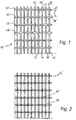
- Figs 1 and 2 correspond to Figs 2 and 6 of US patent 5,944,197
- Fig 1 illustrates an enlarged view of part of a piece of wirecloth which is to form a screen which includes a plurality of parallel warp wires, such as at 12', 14', 16' and 18' which are crossed by and interwoven with a plurality of parallel weft wires such as at 22', 24', 26' and 28' at their intersections.
- Fig 1 shows the rectangular openings between the warp and weft wires which are maintained in the untensioned cloth making up the screen described in US 5,944,197 by calendering the wirecloth after weaving and before it is secured to a support as described elsewhere in US 5,944,197.
- warp wires 12', 14', 16' and 18' there are a greater number of warp wires 12', 14', 16' and 18' than weft wires 22', 24', 26' and 28' per unit or given area.
- the woven warp and weft wires form a plurality of intersections which, in turn, form rectangular openings, such as openings 32' 34' and 36'.
- the rectangular openings have a length dimension L and a width dimension W.
- the length of the rectangular openings L to the width of the rectangular openings W may be expressed as a ratio.
- the length to width ratio which is optimal for each opening has been found to be between approximately 2.7 to 2.8.
- the method of making the screen involves calendering the top or uppermost screen cloth between a set of rollers. Calendering the screen cloth compresses the cloth at the warp and weft intersections. This serves to discourage movement between the warp and weft wires and assist in locking the intersections of the warp and weft wires in place.
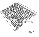
- Fig 2 shows a top view of a screen cloth 74' after completion of the calendering process.
- the intersections, or knuckles, such as 76' and 78' are flattened by the rollers. Additionally, although not visible, where the warp and weft wires intersect and touch each other, the wires indent or conform slightly to each other.
- the length of each opening to the diameter of the weft wires may be expressed as a ratio.
- the optimal ration of the length of each opening to the diameter of the wires is a ratio of between approximately 5.5 to 5.7.
- Fig 2 shows how the calendering step flattens and, with the indentation on the crossing surfaces, weakens the wires where one crosses another at points of intersection, which is avoided by the present invention
- Fig 1 illustrates the relationship of the length of the openings L to the diameter of the weft wires d.
- the filter screen can be used as a filter in vibrating filtration equipment such as shakers which are used in the oil drilling industry for separating solids from the liquid phase of oil and water based muds retrieved from drilling operations.
- vibrating filtration equipment such as shakers which are used in the oil drilling industry for separating solids from the liquid phase of oil and water based muds retrieved from drilling operations.
- Such a screen is described in Patent Specification No WO95/23655.
- This screen has upper and lower wire mesh cloths of differing qualities stretched over a metal rod reinforced frame of plastics material to which the cloths, after tensioning, are bonded by adhesive. Later Patent Specification No.
- WO98/37988 describes a frame to which the tensioned cloths can be bonded by heat softening the surface of the frame and pressing relevant parts of the cloths into the softened plastics material, the bond being completed by then allowing the plastics material to cool and cure.
- the method and apparatus described herein provides a method of manufacturing a filtering screen according to which a frame of plastics coated metal or reinforced plastics material is located in a jig, at least one wire cloth is placed over the frame and its edges are gripped by pneumatically operated clamps carried by the jig, the clamps are pneumatically driven outwardly of the frame to tension the cloth in orthogonal directions, the tensioned cloth is pressed against the frame by a heated platen in order to bond the cloth to the frame and after completion of the bonding step the clamps are released, the frame is removed from the jig and where necessary the cloth trimmed back to the edges of the frame.
- the apparatus comprises a jig for locating at least one such frame of plastics coated metal or reinforced plastics material, pneumatically operated clamps carried by the jig for gripping the edges of a metal wire cloth placed over the at least one frame, pneumatically driven tensioning means on the jig for driving the clamps outwardly from the frame to tension the cloth in orthogonal directions, a platen, means for heating the platen, means for driving the heated platen and/or the jig to press the cloth against the frame in order to locally melt the plastics material and allow the cloth to become embedded therein, and then to retract the platen and/or jig to allow the at least one frame and cloth to cool in order to bond the cloth to the frame, and to allow the frame then to be removed from the jig after release of the clamps.
- Two or three layers of wire mesh cloth can be bonded to the frame.
- a lower cloth of coarser mesh is located below at least one finer mesh cloth, and preferably two finer mesh cloths having slightly differing mesh sizes are laid over the coarser mesh cloth, and all three are bonded to the frame.
- the plastics material of the frame is typically polypropylene.
- the frame itself has a rectangular periphery with a lattice of orthogonal intersecting bars.
- the plastics material forming the upper surface of the frame is softened and the tensioned cloths are pressed into the softened plastics material and become embedded therein.
- the bond is completed by allowing the frame to cool and the plastics material to cure. It is possible for the upper surface of the frame to be ridged to aid the bonding step, in that it is then only necessary for the heated platen used to press the cloths against the frame, to soften the ridges which then accept the wire mesh to form the bond.
- a heat resistant non-stick fabric such as PTFE glass fabric, is preferably laid over the cloths prior to the bonding step. The fabric is removed on completion of the bonding step.
- a separate set of pneumatically operated clamps is provided for each cloth.
- a cloth tensioning mechanism is provided for the clamps along at least two adjacent sides, and preferably all four sides, of each cloth. The cloths can thus be individually and differentially tensioned as appropriate for the use to which the screen is to be put, prior to being collectively bonded to the frame.
- Each clamp comprises a fixed pair of jaws and an inflatable envelope between them for use in gripping the edge of the wire cloth.
- a thin aluminium plate separates the envelope from the cloth.
- the envelope presses the aluminium plate towards one of the jaws, which is preferably lined with a rubber (or like material) strip, typically 3cm wide, to improve the grip on the edge of the cloth sandwiched between the plate and the jaw.
- a control panel is provided to enable a jig operator to activate the pneumatic clamps and the pneumatic tensioning means.
- Preferably four control panels are provided, so that the operator can feed the cloth into the clamps along one side of the frame and activate these clamps to clamp that edge of the cloth using one control panel, before moving to another side of the fame and repeating the procedure for that side of the frame, and so on.
- there are two or more levels of clamps and tensioning mechanisms one level for each layer of cloth, the first cloth is individually clamped and tensioned on all four sides, and then the next, in a similar manner until all the cloths have been clamped and tensioned as appropriate.
- the clamping and tensioning of the cloths is performed at a first station remote from a second station at which the bonding occurs.
- Pneumatic power for the clamps and tensioning mechanisms is therefore supplied to the jig through a flexible supply cable, in order to allow for the movement of the jig between the stations.
- the at least one frame is loaded into a jig carried by a cradle which, after the cloths have been clamped and tensioned, is conveyed to the second station containing the heated platen.
- the cradle preferably has wheels running on rails along which the cradle is driven between the first and second stations by a linear drive, conveniently a Festo® linear pneumatic drive.
- the platen is preferably pre-heated and when in position, the jig cradle is raised up to the platen by a hydraulic ram, to commence the bonding step.
- the ram may act against the underside of the cradle to lift it off the rails on which the cradle is driven between the first and second stations.
- the fabric may be placed on the cloth at the first or second station, or in transit.
- the platen is typically pre-heated to a temperature in the range 200 to 300 degrees C, preferably about 250 degrees C.
- the hydraulic pressure to the ram is adjustable in the range 500 to 2000 psi (3.45 ⁇ 10 6 - 1.38 ⁇ 10 7 Pa) to suit the screen materials, and in particular the cloth or cloth combinations used.
- the hydraulic pressure to effect the squeeze and heating and bonding step is typically applied for a period of time in the range 30 seconds to 2 minutes.
- the jig cradle and platen are separated to allow the material to cool and cure, and finally the jig cradle is conveyed back from the second station to the clamping and tensioning station, to allow the operator to release the clamps, remove the protective fabric, remove the frame or frames from the jig cradle, and trim the cloths extending beyond the edges of the frame(s).
- two frames are covered at a time, arranged side-by-side, and large area pieces of wire cloth, one for each layer, are stretched over both frames. After the bonding step the large area(s) of cloth are cut along a line between the two side-by-side frames.
- the clamps of any one layer are preferably movable outwardly of the frame individually and independently of each other, i.e. each clamp has a spearate associated tensioning mechanism, so that any localised slack in the cloth can be taken up.
- a breaker bar may be located immediately in front of each line of clamps each of the sides of the frame, and the cloth(s) move over it as the cloth(s) are tensioned, thereby to remove any ripples in the cloth.
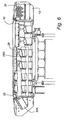
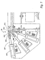
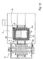
- the illustrated apparatus comprises a supporting framework 10 which at one end supports a cradle 12 forming a jig for enabling assembly of screen frames at an assembly station 14, and which at the other end is integrated with a heating platen support unit 16 constituting a bonding station 18.
- the cradle 12 has wheels which run on parallel spaced apart rails 22, 22A to enable the cradle to be moved between the two stations by a drive 23 (see Fig 10). At least one rail and the wheels corresponding therewith are designed to ensure that the cradle moves in a straight path.
- the drive includes a pin 25 which engages in a groove 27 in plate 29, which latter is secured to and extends from the cradle (see Fig 10).
- the drive 23 is a Festo® linear pneumatic drive.
- a flexible services umbilical cord 24 conveys electrics and pneumatics to the cradle.
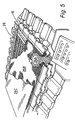
- FIG. 1 At the screen assembly station, two GRP screen support frames 26, one of which is shown in Fig 3, are laid side by side in the jig cradle 12.
- Fig 4 shows one of the frames 26 located in the cradle 12, with the space for a second frame 26 beside it.
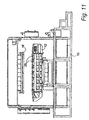
- the plan view of the apparatus (Fig 12) also shows one frame located in the jig.
- Each frame 26 comprises a rectilinear grid of orthogonally intersecting, wire reinforced glass fibre reinforced polypropylene bars as described in Patent Specifications WO95/23655 and WO98/37988. In known manner, the upper surfaces of the peripheral edges and intersecting bars of the frame are moulded with upstanding ridges.
- woven wire filter cloths are laid in turn over the frames, and the edges of each cloth inserted into and gripped by pneumatic clamp units 28 carried by the jig before the next cloth is applied.
- the pneumatic clamp units are shown in more detail in Fig 7.
- the warps and wefts of the cloths define rectangular openings and the cloths are laid over the frames with the longer dimensions of the rectangular openings in the cloth parallel to the longer edges of each frame.
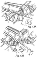
- Each clamp comprises fixed upper and lower jaws 28A, 28B the lower of which carries on its upwardly facing surface an inflatable envelope 28C over which, lies a protective aluminium plate 28D.
- a cloth edge is inserted between 28D and a rubber strip 28E on the underside surface of the upper jaw, so that when 28C is inflated the cloth is clamped between plate 28D and the upper jaw, the rubber strip 28E reducing the risk of slip occurring when the cloth is tensioned.
- the edge of a wire cloth is pulled over the breaker bar 31 and inserted between the jaws 28A, 28B between the rubber strip and the aluminium plate.
- the envelope is then inflated to grip the cloth between the rubber strip and the plate with a pressure sufficient to withstand the tensioning forces subsequently to be applied to the cloth.
- each aluminium plate 28D is upturned to form a lip which engages in a groove in the underside of the upper jaw 28A near the rear edge thereof.
- jaws 28A, 28B are joined at their rear to form a single assembly carried by the piston 28F of a double acting pneumatic cylinder 28G.
- the double acting pneumatic cylinder and piston 28G, 28F constitute a tensioning device and there is one such device for each clamp unit.
- Supplying air to the forward end of the cylinder 28G forces the piston rearwardly, and thereby the jaw assembly, back away from the jig to stretch the gripped cloth over a breaker bar 32 (see Fig. 6) at the periphery of the jig.
- Supplying air to the rear end of the cylinder moves the jaw assembly forward to its rest position nearer the jig as shown in Fig 13A. This is effected after the cloth has been bonded to the frame and the jaws released, as later described.
- the breaker bar 32 prevents any local rippling of the wire cloth during tensioning.
- Three layers of clamp units 28 are provided, to allow up to three cloths to be laid over and secured to the frames.
- Three lines of clamp units 28 are provided on all four sides of the cradle, and a master control panel 30 (see Figs 6 & 12) is provided at one corner, and three slave control panels 30A, 30B and 30C are located at the other corners, so that an operator can control the clamps and tensioning devices along successive sides of the cradle individually, by simply moving from one side to the next therearound.
- each tensioning device constituted by the aforesaid double acting pneumatic cylinder and piston, is operable independently, to stretch the cloth over the breaker bars 32 extending along the four edges of the jig cradle, whereby to ensure that the cloth is uniformly tensioned without ripples or creases.
- the process is repeated for each cloth, a first coarse mesh cloth being located between the jaws of the lowest line of clamps 28, a finer mesh cloth in the next line of clamps, and another fine mesh cloth in the third line of clamps, the mesh size of the two fine mesh cloths being similar but not identical.
- a heat resistant non-stick fabric e.g. PTFE glass fabric
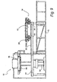
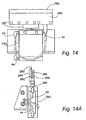
- Fig 5 shows the jig 12 with the two frames 26 located therein, upper and lower wire mesh cloths 26A and 26B cut away in part, stretched over the frame, and the release fabric 26C, also cut away in part, laid over the cloths.
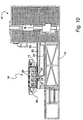
- the jig is raised and lowered by a platform 31 acted on by a hydraulic ram 34, the platform 31 engaging the underside of the jig 12 to lift it, and in so doing lifting the wheels 33, 35 off the rails 22, 22A.
- the cloth on the screens is brought into contact with the platen 36, which is pre-heated by an electric heating element (not shown).
- the heated platen softens the ridges on the upper edges of the interstices and the side flanges of the plastics frames, and the warp and weft wires of the tensioned cloths are pressed into the softened material.
- the ridging of the side flanges, and interstices aids the bonding process, as described in the aforementioned published International Patent Specification No. WO 98/37988.
- the screen assembly is then lowered and moved back to the assembly station.
- the PTFE release fabric is stripped off, the tension on the cloths is released, the screen cloths are cut between the two frames, each frame is removed from the jig, and the protruding edges of the wireloth are trimmed back to the edges of the frames by for example using an angle grinder.
- Manufacture of the screens is then complete, and the jig is now ready to receive the next two frames and layers of cloth to make the next two screens.
- the bonding of the cloths to the interstices as well as to the edges of each frame serves to maintain the shape and length to width ratios of the warp and weft defining openings in the cloths.
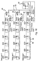
- FIGs 14 and 14A show the air supply lines to the clamp units. Air for inflating the envelope 28C in the jaws 28A, 28B is supplied through air line 40. Complete evacuation of the envelope is required fully to open the space between the jaws prior to insertion of the edges of a fresh wire mesh cloth and this is achieved by applying vacuum to line 40.
- Air for operation of the double acting cylinder 28G is supplied through air lines 42, 44.
- Supplying air through line 42 drives the piston 28F, and thus the clamp, outwardly of the jig in order to tension a wire mesh cloth clamped between the jaws.
- Supplying air through line 44 drives the clamp back towards the jig at the end of the operational sequence, so that the clamps are back in the positions shown in Fig 13A ready to receive the next screen cloths for bonding to the next pair of frames.
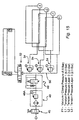
- the pneumatic control circuit for the clamps and tensioning devices is shown in Fig 15.
- Air under pressure is supplied via an on/off valve 46 to a pressure adjustable valve 48 and associated pressure meter 48A and thence through a filter and valve unit 49 to a pressure line 50 from which air can be supplied via a pneumatic switching circuit 52 to operate the clamps and tensioning devices.
- the switching circuit is controlled by buttons on the control panels at the corners of the jog, those buttons being respectively labelled L3, L2, L1 and P1 in the drawing.
- Each line pressure for the clamp and tensioning devices is adjustable by means of pressure adjusters and associated meters 54.
- a typical line pressure P1 for operating the clamps may be 5.5 bar, and typical tensioning pressures may be 4.8 bar (L3) for the uppermost layer of tensioning devices, 3.0 bar (L2) for the intermediate layer and 2.0 bar (L1) for the bottom layer.
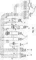
- Figs 16 and 17 show the set up of the pneumatics for the clamp units.
- the frames to which the wire mesh cloths are to be bonded are rectangular, with two shorter sides A and B and two longer sides C and D.
- the two frames are located in the jig with their shorter sides A and B in line, thus requiring six clamp units along each of the aligned edges, (twelve in all) for a cloth laid over both frames.
- Four clamp units are provided along each longer side of the frames at opposite ends of the jig (eight in all).
- Fig 16 shows the set up for six clamp units along one side of the jig; this set up is repeated for the other side.
- Fig 17 shows the set up for the four clamp units along the longer ends of the jig.
- the set up of Fig 17 is also repeated at the opposite end. In both figures, the set up is shown for the clamp units in all three layers.
- valves 56 control the inflation and collapse of the envelopes in the clamps through lines 58 and 60. Venting the envelopes to atmosphere via 60 releases the cloths to allow their edges to be removed. Applying vacuum to 60 by using 62, collapses the envelopes to facilitate the insertion of new cloth between the clamping jaws.
- Valve units 64 control the supply of air to the pneumatic cylinder tensioning devices through lines 65, 66, line 65 for tensioning and line 66 for untensioning.
- reference 68 indicates the fused electrical power input terminals
- reference 69 indicates the power supply to the motor driving an oil pump for supplying hydraulic oil under pressure to the ram which lifts and lowers the cradle at the bonding station
- reference 70 indicates the power supply to a photoelectric safety circuit which is provided to stop and reverse the hydraulic drive if a light beam in the path of the cradle across the entrance to the bonding station is interrupted for any reason while the cradle is being lifted towards the heating platen
- reference 71 indicates the power supply enabling computer control of the sequence of the operating procedure of the apparatus
- reference 72 indicates the power supply for all AC solenoid valves employed in the pneumatic circuits
- reference 74 is the power supply for all DC solenoid valves
- reference 76 indicates the power supply to the heater used in heating the platen at the bonding station.
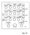
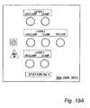
- Figs 19 and 19A respectively show the master control panel 30 at one corner of the jig, and one of the secondary (or slave) control panels 30A, 30B, 30C at one of the other corners of the jig.
- the buttons are marked with their functions.
- the main panel 30 and each secondary panel 30A, 30B, 30C provides for clamping, unclamping and evacuation of the clamp envelops, along the first, second, third and fourth sides of the jig respectively, if appropriate for all three layers of cloth.
- the main control panel 30 additionally provides for tensioning and untensioning along all four sides of the jig, including the first side, which is where the operator starts the loading of the jig.
- the operator having first located the edge of a cloth in the clamps along the first side of the jig, uses the main control panel 30 to operate those clamps to clamp that edge, and then moves round the jig to clamp the edges of the cloth in sequence on the second, third and fourth sides. This brings the operator back to the main control panel, at which the appropriate tensioning button can be pressed to operate all the pneumatic cylinder tensioning devices simultaneously so all the clamps for one layer are moved outwardly at the same time, thus tensioning the cloth appertaining to that layer.
- the operator can use the main control panel 30 first to apply pressure to reverse all the tensioning pneumatic cylinders of all the cloth layers. All the clamping can be released by evacuating all the inflated envelopes to atmosphere, and the latter can be flattened to assist in inserting more wire cloth edges, by applying vacuum to all the envelopes.
Landscapes
- Engineering & Computer Science (AREA)
- Manufacturing & Machinery (AREA)
- Chemical & Material Sciences (AREA)
- Chemical Kinetics & Catalysis (AREA)
- Treatment Of Fiber Materials (AREA)
- Separation Of Solids By Using Liquids Or Pneumatic Power (AREA)
- Photoreceptors In Electrophotography (AREA)
- Glass Compositions (AREA)
- Overhead Projectors And Projection Screens (AREA)
- Combined Means For Separation Of Solids (AREA)
- Treatment Of Sludge (AREA)
- Filtering Materials (AREA)
- Processing And Handling Of Plastics And Other Materials For Molding In General (AREA)
- Stabilization Of Oscillater, Synchronisation, Frequency Synthesizers (AREA)
- Control Of Motors That Do Not Use Commutators (AREA)
- Valve Device For Special Equipments (AREA)
- Separation Of Suspended Particles By Flocculating Agents (AREA)
Priority Applications (2)
| Application Number | Priority Date | Filing Date | Title |
|---|---|---|---|
| DK02774984T DK1444056T3 (da) | 2001-11-10 | 2002-11-05 | Sigtesi |
| EP04029422A EP1518610A3 (en) | 2001-11-10 | 2002-11-05 | Sifting screen |
Applications Claiming Priority (3)
| Application Number | Priority Date | Filing Date | Title |
|---|---|---|---|
| GBGB0127085.9A GB0127085D0 (en) | 2001-11-10 | 2001-11-10 | Improved screen for separating solids from liquids |
| GB0127085 | 2001-11-10 | ||
| PCT/GB2002/005018 WO2003041878A1 (en) | 2001-11-10 | 2002-11-05 | Sifting screen |
Related Child Applications (1)
| Application Number | Title | Priority Date | Filing Date |
|---|---|---|---|
| EP04029422A Division EP1518610A3 (en) | 2001-11-10 | 2002-11-05 | Sifting screen |
Publications (2)
| Publication Number | Publication Date |
|---|---|
| EP1444056A1 EP1444056A1 (en) | 2004-08-11 |
| EP1444056B1 true EP1444056B1 (en) | 2005-06-08 |
Family
ID=9925582
Family Applications (2)
| Application Number | Title | Priority Date | Filing Date |
|---|---|---|---|
| EP02774984A Expired - Lifetime EP1444056B1 (en) | 2001-11-10 | 2002-11-05 | Sifting screen |
| EP04029422A Withdrawn EP1518610A3 (en) | 2001-11-10 | 2002-11-05 | Sifting screen |
Family Applications After (1)
| Application Number | Title | Priority Date | Filing Date |
|---|---|---|---|
| EP04029422A Withdrawn EP1518610A3 (en) | 2001-11-10 | 2002-11-05 | Sifting screen |
Country Status (11)
| Country | Link |
|---|---|
| US (1) | US7316321B2 (enExample) |
| EP (2) | EP1444056B1 (enExample) |
| JP (1) | JP4237060B2 (enExample) |
| AT (1) | ATE297264T1 (enExample) |
| BR (1) | BR0214012B1 (enExample) |
| CA (1) | CA2465437C (enExample) |
| DE (2) | DE04029422T1 (enExample) |
| GB (2) | GB0127085D0 (enExample) |
| NO (1) | NO330229B1 (enExample) |
| WO (1) | WO2003041878A1 (enExample) |
| ZA (1) | ZA200208892B (enExample) |
Cited By (1)
| Publication number | Priority date | Publication date | Assignee | Title |
|---|---|---|---|---|
| CN102264483A (zh) * | 2008-12-23 | 2011-11-30 | 联合电线有限公司 | 改进的细分筛 |
Families Citing this family (26)
| Publication number | Priority date | Publication date | Assignee | Title |
|---|---|---|---|---|
| US20050242003A1 (en) | 2004-04-29 | 2005-11-03 | Eric Scott | Automatic vibratory separator |
| BR0208744B1 (pt) * | 2002-05-08 | 2011-05-31 | método de fabricar uma peneira de filtragem e aparelho para executar o mesmo. | |
| US8312995B2 (en) | 2002-11-06 | 2012-11-20 | National Oilwell Varco, L.P. | Magnetic vibratory screen clamping |
| US8172740B2 (en) * | 2002-11-06 | 2012-05-08 | National Oilwell Varco L.P. | Controlled centrifuge systems |
| GB0308475D0 (en) | 2003-04-12 | 2003-05-21 | United Wire Ltd | Filtering screen |
| US8118172B2 (en) * | 2005-11-16 | 2012-02-21 | National Oilwell Varco L.P. | Shale shakers with cartridge screen assemblies |
| US8201693B2 (en) | 2006-05-26 | 2012-06-19 | National Oilwell Varco, L.P. | Apparatus and method for separating solids from a solids laden liquid |
| US20080083566A1 (en) | 2006-10-04 | 2008-04-10 | George Alexander Burnett | Reclamation of components of wellbore cuttings material |
| US8231010B2 (en) | 2006-12-12 | 2012-07-31 | Varco I/P, Inc. | Screen assemblies and vibratory separators |
| US20080190822A1 (en) * | 2007-02-09 | 2008-08-14 | Lumsden Corporation | Screen for a Vibratory Separator Having Tension Reduction Feature |
| US8622220B2 (en) * | 2007-08-31 | 2014-01-07 | Varco I/P | Vibratory separators and screens |
| US7980392B2 (en) * | 2007-08-31 | 2011-07-19 | Varco I/P | Shale shaker screens with aligned wires |
| US20090145836A1 (en) * | 2007-12-11 | 2009-06-11 | Paul William Dufilho | Vibratory separator screens & seals |
| US8133164B2 (en) * | 2008-01-14 | 2012-03-13 | National Oilwell Varco L.P. | Transportable systems for treating drilling fluid |
| US9415420B2 (en) * | 2008-06-16 | 2016-08-16 | M-I L.L.C. | Laminated screens |
| US20100038143A1 (en) * | 2008-08-14 | 2010-02-18 | George Alexander Burnett | Drill cuttings treatment systems |
| US9073104B2 (en) | 2008-08-14 | 2015-07-07 | National Oilwell Varco, L.P. | Drill cuttings treatment systems |
| US9079222B2 (en) * | 2008-10-10 | 2015-07-14 | National Oilwell Varco, L.P. | Shale shaker |
| US8556083B2 (en) | 2008-10-10 | 2013-10-15 | National Oilwell Varco L.P. | Shale shakers with selective series/parallel flow path conversion |
| US8113356B2 (en) * | 2008-10-10 | 2012-02-14 | National Oilwell Varco L.P. | Systems and methods for the recovery of lost circulation and similar material |
| US20100181265A1 (en) * | 2009-01-20 | 2010-07-22 | Schulte Jr David L | Shale shaker with vertical screens |
| US20110198269A1 (en) * | 2010-02-16 | 2011-08-18 | Grant Young | Vibratory screen device |
| KR101296333B1 (ko) * | 2011-07-04 | 2013-08-14 | 이민철 | 골재 선별용 스크린 |
| US9643111B2 (en) | 2013-03-08 | 2017-05-09 | National Oilwell Varco, L.P. | Vector maximizing screen |
| CN105562565B (zh) * | 2016-02-21 | 2023-09-26 | 江苏巨能机械有限公司 | 滤网安装设备 |
| NL2034261B1 (en) * | 2023-03-03 | 2024-09-09 | Rollman Holding B V | A screen assembly for use in a shale shaker |
Family Cites Families (14)
| Publication number | Priority date | Publication date | Assignee | Title |
|---|---|---|---|---|
| US2723032A (en) * | 1950-12-18 | 1955-11-08 | Mining Process & Patent Co | Vibrating screens |
| US4120785A (en) * | 1976-02-23 | 1978-10-17 | Mitsuboshi Belting Limited | Rubber screens for vibratory screening apparatus |
| US4575421A (en) * | 1984-03-08 | 1986-03-11 | Derrick Manufacturing Corporation | Non-clogging wear-reducing screen assembly for vibrating screening machine |
| GB8418658D0 (en) * | 1984-07-21 | 1984-08-22 | Thule United Ltd | Filtering screens |
| GB2175222B (en) * | 1984-07-21 | 1989-04-26 | Thule United Ltd | Improvements in filtering screens |
| US5615776A (en) * | 1992-04-21 | 1997-04-01 | Alfa Laval Separation Ab | Mounting & tensioning arrangements for screens |
| CA2152602C (en) * | 1993-01-13 | 1999-06-29 | John James Bakula | Undulating screen for vibratory screening machine and method of fabrication thereof |
| US5851393A (en) * | 1995-11-14 | 1998-12-22 | Emerson Electric Co. | Screen assembly |
| DE19706601C1 (de) * | 1997-02-20 | 1998-11-12 | Buehler Ag | Siebrahmen für Plansichter und Verfahren zu dessen Herstellung |
| AU724886B2 (en) * | 1997-03-01 | 2000-10-05 | United Wire Limited | Improved filtering screen and support frame therefor |
| US5944197A (en) * | 1997-04-24 | 1999-08-31 | Southwestern Wire Cloth, Inc. | Rectangular opening woven screen mesh for filtering solid particles |
| US5950841A (en) * | 1998-07-22 | 1999-09-14 | Emerson Electric Co. | Screen assembly for a vibratory separator |
| US6932883B2 (en) * | 1998-10-30 | 2005-08-23 | Varco I/P, Inc. | Screens for vibratory separators |
| US6237780B1 (en) * | 1999-11-03 | 2001-05-29 | Tuboscope I/P, Inc. | Vibratory separator screens |
-
2001
- 2001-11-10 GB GBGB0127085.9A patent/GB0127085D0/en not_active Ceased
-
2002
- 2002-11-01 ZA ZA200208892A patent/ZA200208892B/xx unknown
- 2002-11-05 JP JP2003543753A patent/JP4237060B2/ja not_active Expired - Fee Related
- 2002-11-05 EP EP02774984A patent/EP1444056B1/en not_active Expired - Lifetime
- 2002-11-05 AT AT02774984T patent/ATE297264T1/de not_active IP Right Cessation
- 2002-11-05 GB GB0225724A patent/GB2382037B/en not_active Expired - Fee Related
- 2002-11-05 CA CA002465437A patent/CA2465437C/en not_active Expired - Fee Related
- 2002-11-05 BR BRPI0214012-8A patent/BR0214012B1/pt not_active IP Right Cessation
- 2002-11-05 DE DE04029422T patent/DE04029422T1/de active Pending
- 2002-11-05 US US10/493,750 patent/US7316321B2/en not_active Expired - Lifetime
- 2002-11-05 WO PCT/GB2002/005018 patent/WO2003041878A1/en not_active Ceased
- 2002-11-05 DE DE60204585T patent/DE60204585T2/de not_active Expired - Lifetime
- 2002-11-05 EP EP04029422A patent/EP1518610A3/en not_active Withdrawn
-
2004
- 2004-06-10 NO NO20042405A patent/NO330229B1/no not_active IP Right Cessation
Cited By (3)
| Publication number | Priority date | Publication date | Assignee | Title |
|---|---|---|---|---|
| CN102264483A (zh) * | 2008-12-23 | 2011-11-30 | 联合电线有限公司 | 改进的细分筛 |
| US8789707B2 (en) | 2008-12-23 | 2014-07-29 | United Wire Limited | Sifting screen |
| CN102264483B (zh) * | 2008-12-23 | 2015-06-17 | 联合电线有限公司 | 改进的细分筛 |
Also Published As
| Publication number | Publication date |
|---|---|
| WO2003041878A1 (en) | 2003-05-22 |
| BR0214012A (pt) | 2004-10-13 |
| EP1518610A3 (en) | 2005-04-06 |
| JP2005508747A (ja) | 2005-04-07 |
| CA2465437A1 (en) | 2003-05-22 |
| DE04029422T1 (de) | 2005-09-01 |
| GB0127085D0 (en) | 2002-01-02 |
| DE60204585T2 (de) | 2006-03-16 |
| ZA200208892B (en) | 2003-05-05 |
| EP1444056A1 (en) | 2004-08-11 |
| US20050150821A1 (en) | 2005-07-14 |
| ATE297264T1 (de) | 2005-06-15 |
| CA2465437C (en) | 2007-10-02 |
| US7316321B2 (en) | 2008-01-08 |
| EP1518610A2 (en) | 2005-03-30 |
| JP4237060B2 (ja) | 2009-03-11 |
| NO20042405L (no) | 2004-06-10 |
| GB2382037A (en) | 2003-05-21 |
| DE60204585D1 (de) | 2005-07-14 |
| GB0225724D0 (en) | 2002-12-11 |
| BR0214012B1 (pt) | 2011-06-28 |
| GB2382037B (en) | 2003-10-22 |
| NO330229B1 (no) | 2011-03-07 |
Similar Documents
| Publication | Publication Date | Title |
|---|---|---|
| EP1444056B1 (en) | Sifting screen | |
| JP2005508747A5 (enExample) | ||
| US8898905B2 (en) | Manufacture of a filter screen | |
| AU690096B2 (en) | Undulating screen for vibratory screening machine and methodof fabrication thereof | |
| EP1501642B1 (en) | Manufacture of a filtering screen | |
| US7938926B2 (en) | Manufacture of a filtering system | |
| DE60313011T2 (de) | Sieb aus drahtgewebe |
Legal Events
| Date | Code | Title | Description |
|---|---|---|---|
| PUAI | Public reference made under article 153(3) epc to a published international application that has entered the european phase |
Free format text: ORIGINAL CODE: 0009012 |
|
| 17P | Request for examination filed |
Effective date: 20040430 |
|
| AK | Designated contracting states |
Kind code of ref document: A1 Designated state(s): AT BE BG CH CY CZ DE DK EE ES FI FR GB GR IE IT LI LU MC NL PT SE SK TR |
|
| AX | Request for extension of the european patent |
Extension state: AL LT LV MK RO SI |
|
| 17Q | First examination report despatched |
Effective date: 20040920 |
|
| GRAP | Despatch of communication of intention to grant a patent |
Free format text: ORIGINAL CODE: EPIDOSNIGR1 |
|
| GRAS | Grant fee paid |
Free format text: ORIGINAL CODE: EPIDOSNIGR3 |
|
| GRAA | (expected) grant |
Free format text: ORIGINAL CODE: 0009210 |
|
| AK | Designated contracting states |
Kind code of ref document: B1 Designated state(s): AT BE BG CH CY CZ DE DK EE ES FI FR GB GR IE IT LI LU MC NL PT SE SK TR |
|
| PG25 | Lapsed in a contracting state [announced via postgrant information from national office to epo] |
Ref country code: IT Free format text: LAPSE BECAUSE OF FAILURE TO SUBMIT A TRANSLATION OF THE DESCRIPTION OR TO PAY THE FEE WITHIN THE PRESCRIBED TIME-LIMIT;WARNING: LAPSES OF ITALIAN PATENTS WITH EFFECTIVE DATE BEFORE 2007 MAY HAVE OCCURRED AT ANY TIME BEFORE 2007. THE CORRECT EFFECTIVE DATE MAY BE DIFFERENT FROM THE ONE RECORDED. Effective date: 20050608 Ref country code: AT Free format text: LAPSE BECAUSE OF FAILURE TO SUBMIT A TRANSLATION OF THE DESCRIPTION OR TO PAY THE FEE WITHIN THE PRESCRIBED TIME-LIMIT Effective date: 20050608 Ref country code: FI Free format text: LAPSE BECAUSE OF FAILURE TO SUBMIT A TRANSLATION OF THE DESCRIPTION OR TO PAY THE FEE WITHIN THE PRESCRIBED TIME-LIMIT Effective date: 20050608 Ref country code: SK Free format text: LAPSE BECAUSE OF FAILURE TO SUBMIT A TRANSLATION OF THE DESCRIPTION OR TO PAY THE FEE WITHIN THE PRESCRIBED TIME-LIMIT Effective date: 20050608 Ref country code: EE Free format text: LAPSE BECAUSE OF FAILURE TO SUBMIT A TRANSLATION OF THE DESCRIPTION OR TO PAY THE FEE WITHIN THE PRESCRIBED TIME-LIMIT Effective date: 20050608 Ref country code: CZ Free format text: LAPSE BECAUSE OF FAILURE TO SUBMIT A TRANSLATION OF THE DESCRIPTION OR TO PAY THE FEE WITHIN THE PRESCRIBED TIME-LIMIT Effective date: 20050608 Ref country code: TR Free format text: LAPSE BECAUSE OF FAILURE TO SUBMIT A TRANSLATION OF THE DESCRIPTION OR TO PAY THE FEE WITHIN THE PRESCRIBED TIME-LIMIT Effective date: 20050608 |
|
| REG | Reference to a national code |
Ref country code: GB Ref legal event code: FG4D |
|
| REG | Reference to a national code |
Ref country code: CH Ref legal event code: NV Representative=s name: SCHNEIDER FELDMANN AG PATENT- UND MARKENANWAELTE Ref country code: CH Ref legal event code: EP |
|
| REG | Reference to a national code |
Ref country code: DK Ref legal event code: T3 |
|
| REF | Corresponds to: |
Ref document number: 60204585 Country of ref document: DE Date of ref document: 20050714 Kind code of ref document: P |
|
| REG | Reference to a national code |
Ref country code: IE Ref legal event code: FG4D |
|
| PG25 | Lapsed in a contracting state [announced via postgrant information from national office to epo] |
Ref country code: BG Free format text: LAPSE BECAUSE OF FAILURE TO SUBMIT A TRANSLATION OF THE DESCRIPTION OR TO PAY THE FEE WITHIN THE PRESCRIBED TIME-LIMIT Effective date: 20050908 Ref country code: GR Free format text: LAPSE BECAUSE OF FAILURE TO SUBMIT A TRANSLATION OF THE DESCRIPTION OR TO PAY THE FEE WITHIN THE PRESCRIBED TIME-LIMIT Effective date: 20050908 |
|
| PG25 | Lapsed in a contracting state [announced via postgrant information from national office to epo] |
Ref country code: ES Free format text: LAPSE BECAUSE OF FAILURE TO SUBMIT A TRANSLATION OF THE DESCRIPTION OR TO PAY THE FEE WITHIN THE PRESCRIBED TIME-LIMIT Effective date: 20050919 |
|
| REG | Reference to a national code |
Ref country code: SE Ref legal event code: TRGR |
|
| PG25 | Lapsed in a contracting state [announced via postgrant information from national office to epo] |
Ref country code: CY Free format text: LAPSE BECAUSE OF FAILURE TO SUBMIT A TRANSLATION OF THE DESCRIPTION OR TO PAY THE FEE WITHIN THE PRESCRIBED TIME-LIMIT Effective date: 20051105 |
|
| PG25 | Lapsed in a contracting state [announced via postgrant information from national office to epo] |
Ref country code: IE Free format text: LAPSE BECAUSE OF NON-PAYMENT OF DUE FEES Effective date: 20051107 |
|
| PG25 | Lapsed in a contracting state [announced via postgrant information from national office to epo] |
Ref country code: PT Free format text: LAPSE BECAUSE OF FAILURE TO SUBMIT A TRANSLATION OF THE DESCRIPTION OR TO PAY THE FEE WITHIN THE PRESCRIBED TIME-LIMIT Effective date: 20051114 |
|
| PG25 | Lapsed in a contracting state [announced via postgrant information from national office to epo] |
Ref country code: LU Free format text: LAPSE BECAUSE OF NON-PAYMENT OF DUE FEES Effective date: 20051130 Ref country code: MC Free format text: LAPSE BECAUSE OF NON-PAYMENT OF DUE FEES Effective date: 20051130 |
|
| ET | Fr: translation filed | ||
| PLBE | No opposition filed within time limit |
Free format text: ORIGINAL CODE: 0009261 |
|
| STAA | Information on the status of an ep patent application or granted ep patent |
Free format text: STATUS: NO OPPOSITION FILED WITHIN TIME LIMIT |
|
| 26N | No opposition filed |
Effective date: 20060309 |
|
| REG | Reference to a national code |
Ref country code: IE Ref legal event code: MM4A |
|
| REG | Reference to a national code |
Ref country code: FR Ref legal event code: PLFP Year of fee payment: 14 |
|
| REG | Reference to a national code |
Ref country code: FR Ref legal event code: PLFP Year of fee payment: 15 |
|
| REG | Reference to a national code |
Ref country code: FR Ref legal event code: PLFP Year of fee payment: 16 |
|
| PGFP | Annual fee paid to national office [announced via postgrant information from national office to epo] |
Ref country code: BE Payment date: 20190917 Year of fee payment: 18 |
|
| PGFP | Annual fee paid to national office [announced via postgrant information from national office to epo] |
Ref country code: SE Payment date: 20191111 Year of fee payment: 18 Ref country code: DE Payment date: 20191022 Year of fee payment: 18 Ref country code: NL Payment date: 20191114 Year of fee payment: 18 |
|
| PGFP | Annual fee paid to national office [announced via postgrant information from national office to epo] |
Ref country code: FR Payment date: 20191014 Year of fee payment: 18 Ref country code: DK Payment date: 20191112 Year of fee payment: 18 |
|
| PGFP | Annual fee paid to national office [announced via postgrant information from national office to epo] |
Ref country code: CH Payment date: 20191116 Year of fee payment: 18 |
|
| REG | Reference to a national code |
Ref country code: CH Ref legal event code: PFA Owner name: UNITED WIRE LIMITED, GB Free format text: FORMER OWNER: UNITED WIRE LIMITED, GB |
|
| PGFP | Annual fee paid to national office [announced via postgrant information from national office to epo] |
Ref country code: GB Payment date: 20201028 Year of fee payment: 19 |
|
| REG | Reference to a national code |
Ref country code: DE Ref legal event code: R119 Ref document number: 60204585 Country of ref document: DE |
|
| REG | Reference to a national code |
Ref country code: DK Ref legal event code: EBP Effective date: 20201130 |
|
| REG | Reference to a national code |
Ref country code: SE Ref legal event code: EUG |
|
| REG | Reference to a national code |
Ref country code: CH Ref legal event code: PL |
|
| REG | Reference to a national code |
Ref country code: NL Ref legal event code: MM Effective date: 20201201 |
|
| REG | Reference to a national code |
Ref country code: BE Ref legal event code: MM Effective date: 20201130 |
|
| PG25 | Lapsed in a contracting state [announced via postgrant information from national office to epo] |
Ref country code: CH Free format text: LAPSE BECAUSE OF NON-PAYMENT OF DUE FEES Effective date: 20201130 Ref country code: NL Free format text: LAPSE BECAUSE OF NON-PAYMENT OF DUE FEES Effective date: 20201201 Ref country code: LI Free format text: LAPSE BECAUSE OF NON-PAYMENT OF DUE FEES Effective date: 20201130 Ref country code: SE Free format text: LAPSE BECAUSE OF NON-PAYMENT OF DUE FEES Effective date: 20201106 |
|
| PG25 | Lapsed in a contracting state [announced via postgrant information from national office to epo] |
Ref country code: FR Free format text: LAPSE BECAUSE OF NON-PAYMENT OF DUE FEES Effective date: 20201130 |
|
| PG25 | Lapsed in a contracting state [announced via postgrant information from national office to epo] |
Ref country code: DE Free format text: LAPSE BECAUSE OF NON-PAYMENT OF DUE FEES Effective date: 20210601 Ref country code: DK Free format text: LAPSE BECAUSE OF NON-PAYMENT OF DUE FEES Effective date: 20201130 |
|
| GBPC | Gb: european patent ceased through non-payment of renewal fee |
Effective date: 20211105 |
|
| PG25 | Lapsed in a contracting state [announced via postgrant information from national office to epo] |
Ref country code: BE Free format text: LAPSE BECAUSE OF NON-PAYMENT OF DUE FEES Effective date: 20201130 |
|
| PG25 | Lapsed in a contracting state [announced via postgrant information from national office to epo] |
Ref country code: GB Free format text: LAPSE BECAUSE OF NON-PAYMENT OF DUE FEES Effective date: 20211105 |