EP1443618A1 - Appareil de commutation multifonction moyenne tension pour panneau de commande moyenne tension - Google Patents
Appareil de commutation multifonction moyenne tension pour panneau de commande moyenne tension Download PDFInfo
- Publication number
- EP1443618A1 EP1443618A1 EP04001311A EP04001311A EP1443618A1 EP 1443618 A1 EP1443618 A1 EP 1443618A1 EP 04001311 A EP04001311 A EP 04001311A EP 04001311 A EP04001311 A EP 04001311A EP 1443618 A1 EP1443618 A1 EP 1443618A1
- Authority
- EP
- European Patent Office
- Prior art keywords
- knife switch
- combined apparatus
- middle voltage
- driving
- combined
- Prior art date
- Legal status (The legal status is an assumption and is not a legal conclusion. Google has not performed a legal analysis and makes no representation as to the accuracy of the status listed.)
- Withdrawn
Links
Images


Classifications
-
- H—ELECTRICITY
- H02—GENERATION; CONVERSION OR DISTRIBUTION OF ELECTRIC POWER
- H02B—BOARDS, SUBSTATIONS OR SWITCHING ARRANGEMENTS FOR THE SUPPLY OR DISTRIBUTION OF ELECTRIC POWER
- H02B13/00—Arrangement of switchgear in which switches are enclosed in, or structurally associated with, a casing, e.g. cubicle
- H02B13/02—Arrangement of switchgear in which switches are enclosed in, or structurally associated with, a casing, e.g. cubicle with metal casing
- H02B13/025—Safety arrangements, e.g. in case of excessive pressure or fire due to electrical defect
-
- H—ELECTRICITY
- H01—ELECTRIC ELEMENTS
- H01H—ELECTRIC SWITCHES; RELAYS; SELECTORS; EMERGENCY PROTECTIVE DEVICES
- H01H31/00—Air-break switches for high tension without arc-extinguishing or arc-preventing means
- H01H31/003—Earthing switches
Definitions
- the present invention relates to a combined multifunctional middle voltage apparatus for middle voltage electric control panels.
- the automatic breaker is coupled to the line knife switch, the earth knife switch and current transformers which must necessarily have the required mechanical interlocking means for providing an interlocking between the operation of the breaker and that of the knife switches, to prevent false actuations from occurring; the mentioned mechanic interlocking means are conventionally used by interlocking key elements.
- the aim of the present invention is to overcome the above mentioned drawbacks, by providing a combined multifunctional middle voltage apparatus for middle voltage electric control panels, allowing to make a very compact element which can be arranged in a single drive casing or box, together with the related mechanic interlocking means, which are made without using key interlocking devices.
- a main object of the present invention is to provide such a multifunctional middle voltage apparatus for metal enclosed control panels which is specifically designed for providing a IP20 protection between the top and bottom portion thereof, thereby providing a very practical and operatively flexible assembly.
- Another object of the present invention is to provide such a combined apparatus allowing to easily see from the outside of the control panel, the opening and closing positions of the line knife switch blades, thereby providing a visible displaying of the switching function.
- Another object of the present invention is to provide such a middle voltage apparatus which can be constructed with rated middle voltages of 12, 24 and 36 KV.
- Another object of the present invention is to provide such an apparatus allowing to apply, in its insulating housing, toroidal current transformers of a low voltage type, or electronic current transformers.
- Yet another object of the present invention is to provide such a middle voltage apparatus which includes a built-in mechanical system for locking the access door to the cell, which door can be opened only with an open line knife switch and a closed earth knife switch.
- Yet another object of the present invention is to provide such a middle voltage apparatus allowing to make a cell including an automatic breaker having a size smaller than that of the automatic breakers which are at present commercially available, which can be easily associated with other cells of a switching type, and this with a very small building cost, since all the functional parts, such as the related drivers and locking means are already built-in in the apparatus.
- a combined multifunctional middle voltage apparatus for middle voltage electric control panels characterized in that said apparatus comprises a supporting element for supporting insulated poles coupled to a drive casing including a drive shaft for driving an automatic breaker and a drive shaft for driving a line knife switch, in said drive casing being moreover provided mechanical interlocking means between said automatic breaker and line knife switch.
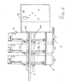
- the combined multifunctional middle voltage apparatus for middle voltage electric control panels comprises a supporting element 1, which is made of a metal material, and has substantially a plate-like shape, and being provided for operating as a supporting element for insulated poles, generally provided in a number of three, and which has been generally indicated by the reference number 2.
- the supporting element 1 is coupled to a drive casing or box 3, of substantially parallelepipedal shape.
- the metal supporting element 1 is designed for operating as a segregating element between the bus bar region and the breaker cell region.
- a drive shaft 10 for driving the earth knife switch operating on the earthing blades 11 is provided.
- the assembly further comprises, under the plate 1, on a side opposite to the drive shaft 10, a further drive shaft for opening and closing the breaker 30, which is coupled to the linkage elements 31 providing a connection with the poles 2.
- Each pole 2 as clearly shown in figure 3, comprises a supporting element 40 operating as a support for the connection of the coupling bars of the head bars and as a plug-in arrangement for the line knife switch.
- a window arrangement 41 For knife switches of a knee lever or pantograph type, is provided a window arrangement 41, allowing to visually monitor the closure condition of the line knife switch blades, thereby rendering visible the sectioning operation.
- each pole 2 can comprise a current reducing unit, of a low voltage type, generally indicated by the reference number 50 and applied to the central pole of figure 4.
- the current reducing unit 50 in particular, can be omitted, as is shown on the right pole of figure 4, and being housed inside an insulating covering 51, as is shown for the left pole.
- the drive casing or box as is clearly shown in figure 6, comprises a drive for the line knife switch, indicated by 60, a breaker drive, indicated by 61, and an earth knife switch drive, indicated by 62.
- Said drive casing or box comprises all the indicating or signalling elements as conventionally included in available breakers.
- the actuating and disactuating operations will be interlocked with one another, to provide a set fixed drive sequence of the cell; in fact, to operate the cell, it is necessary to perform at first the opening of the earth knife switch, then perform the closing of the line knife switch and, finally, the closing or closure of the automatic breaker.
- That same mechanical locking means would not allow to open the earth knife switch with the cell door in an open condition.
- the automatic breaker drive will comprise moreover all the components of commercially available automatic breakers, and would provide all the performance operations as those provided by conventional automatic breakers.
- the drive will be also provided with opening and closing status indicating elements, related to the two knife switches.
- the terminal block including the auxiliary connections (of low voltage) and, in particular, but not limitatedly, for automatically or power driving the breaker, for tele-controlling it, by opening and closing coils, auxiliary contacts for said breaker and two knife switches, in addition to the other connections and toroidal or electronic current transformer to be optionally installed on the poles of the apparatus.
- the invention provides a combined middle or intermediate voltage apparatus, which is very practical and functional and which, moreover, can greatly simplify all the assembling operations, in addition to increasing the operating safety.
- the used materials, as well as the contingent size and shapes can be any, according to requirements.
Applications Claiming Priority (2)
| Application Number | Priority Date | Filing Date | Title |
|---|---|---|---|
| ITMI20030117 | 2003-01-24 | ||
| ITMI20030117 ITMI20030117A1 (it) | 2003-01-24 | 2003-01-24 | Apparecchio combinato di media tensione a piu' funzioni, in particolare per quadri elettrici di media tensione. |
Publications (1)
| Publication Number | Publication Date |
|---|---|
| EP1443618A1 true EP1443618A1 (fr) | 2004-08-04 |
Family
ID=32652451
Family Applications (1)
| Application Number | Title | Priority Date | Filing Date |
|---|---|---|---|
| EP04001311A Withdrawn EP1443618A1 (fr) | 2003-01-24 | 2004-01-22 | Appareil de commutation multifonction moyenne tension pour panneau de commande moyenne tension |
Country Status (2)
| Country | Link |
|---|---|
| EP (1) | EP1443618A1 (fr) |
| IT (1) | ITMI20030117A1 (fr) |
Cited By (2)
| Publication number | Priority date | Publication date | Assignee | Title |
|---|---|---|---|---|
| CN103311812A (zh) * | 2013-06-28 | 2013-09-18 | 浙江天润电力科技有限公司 | 一种带有隔离开关、真空断路器、接地开关的组合电器 |
| CN106409564A (zh) * | 2016-10-21 | 2017-02-15 | 国家电网公司 | 利用刀闸位置与操作机构箱同时闭锁防误操作装置及方法 |
Citations (3)
| Publication number | Priority date | Publication date | Assignee | Title |
|---|---|---|---|---|
| GB1287301A (en) * | 1968-10-07 | 1972-08-31 | Alsthom Cgee | Cubicle switchgear |
| DE3417299A1 (de) * | 1984-02-14 | 1985-10-10 | BBC Aktiengesellschaft Brown, Boveri & Cie., Baden, Aargau | Metallgekapselte, gasisolierte schaltanlage |
| FR2586868A1 (fr) * | 1985-08-29 | 1987-03-06 | Merlin Gerin | Armoire de raccordement interruptible en derivation. |
-
2003
- 2003-01-24 IT ITMI20030117 patent/ITMI20030117A1/it unknown
-
2004
- 2004-01-22 EP EP04001311A patent/EP1443618A1/fr not_active Withdrawn
Patent Citations (3)
| Publication number | Priority date | Publication date | Assignee | Title |
|---|---|---|---|---|
| GB1287301A (en) * | 1968-10-07 | 1972-08-31 | Alsthom Cgee | Cubicle switchgear |
| DE3417299A1 (de) * | 1984-02-14 | 1985-10-10 | BBC Aktiengesellschaft Brown, Boveri & Cie., Baden, Aargau | Metallgekapselte, gasisolierte schaltanlage |
| FR2586868A1 (fr) * | 1985-08-29 | 1987-03-06 | Merlin Gerin | Armoire de raccordement interruptible en derivation. |
Cited By (4)
| Publication number | Priority date | Publication date | Assignee | Title |
|---|---|---|---|---|
| CN103311812A (zh) * | 2013-06-28 | 2013-09-18 | 浙江天润电力科技有限公司 | 一种带有隔离开关、真空断路器、接地开关的组合电器 |
| CN103311812B (zh) * | 2013-06-28 | 2015-07-15 | 浙江天润电力科技有限公司 | 一种带有隔离开关、真空断路器、接地开关的组合电器 |
| CN106409564A (zh) * | 2016-10-21 | 2017-02-15 | 国家电网公司 | 利用刀闸位置与操作机构箱同时闭锁防误操作装置及方法 |
| CN106409564B (zh) * | 2016-10-21 | 2018-06-19 | 国家电网公司 | 利用刀闸位置与操作机构箱同时闭锁防误操作装置及方法 |
Also Published As
| Publication number | Publication date |
|---|---|
| ITMI20030117A1 (it) | 2004-07-25 |
Similar Documents
| Publication | Publication Date | Title |
|---|---|---|
| JP4268991B2 (ja) | 真空絶縁スイッチギヤ | |
| JP4197702B2 (ja) | 真空絶縁スイッチギヤ | |
| EP2645395B1 (fr) | Dispositif de commutation électrique et appareil électrique s'y rapportant | |
| TWI435355B (zh) | Vacuum insulated switch drive | |
| US8462486B2 (en) | Gas-insulated medium-voltage switchgear assembly | |
| JP4841875B2 (ja) | 真空絶縁スイッチギヤ | |
| JP4848018B2 (ja) | 電力用閉鎖配電盤 | |
| EP2431988B1 (fr) | Appareil de commutation électrique et son ensemble de levier | |
| EP3259769B1 (fr) | Appareil de commutation électrique, un ensemble d'interface et dispositif d'affichage correspondant | |
| JP2007014087A (ja) | 真空絶縁スイッチギヤ | |
| EP1226596B1 (fr) | Appareil tripolaire a structure compacte pour stations electriques | |
| US7544907B1 (en) | Special provisions for network protector retrofits | |
| JPH04298934A (ja) | 配線用遮断器の作動ハンドルガード | |
| EP1443618A1 (fr) | Appareil de commutation multifonction moyenne tension pour panneau de commande moyenne tension | |
| KR101168257B1 (ko) | 전자석 엑츄레이터를 탑재한 전자식 배선용 차단기 | |
| CN108074774B (zh) | 用于接地开关的凸轮选择器 | |
| CN113196603B (zh) | 三相开关机构或控制机构 | |
| EP1724804B1 (fr) | Module de réarmement pour un dispositif électrique de sécurité | |
| EP2513658B1 (fr) | Installation de test de câbles pour appareils de commutation | |
| KR101960058B1 (ko) | 가스절연 개폐장치의 구동부와 보조 접점의 원거리 분리 동작 구조 | |
| KR101925408B1 (ko) | 배전반 | |
| JPH0584122B2 (fr) | ||
| CN106921121B (zh) | 一种sf6全绝缘双电源柜 | |
| JP2002354617A (ja) | 複合型ガス絶縁開閉装置 | |
| CN110620347A (zh) | 空气绝缘固定柜 |
Legal Events
| Date | Code | Title | Description |
|---|---|---|---|
| PUAI | Public reference made under article 153(3) epc to a published international application that has entered the european phase |
Free format text: ORIGINAL CODE: 0009012 |
|
| AK | Designated contracting states |
Kind code of ref document: A1 Designated state(s): AT BE BG CH CY CZ DE DK EE ES FI FR GB GR HU IE IT LI LU MC NL PT RO SE SI SK TR |
|
| AX | Request for extension of the european patent |
Extension state: AL LT LV MK |
|
| 17P | Request for examination filed |
Effective date: 20041118 |
|
| AKX | Designation fees paid |
Designated state(s): AT BE BG CH CY CZ DE DK EE ES FI FR GB GR HU IE IT LI LU MC NL PT RO SE SI SK TR |
|
| 17Q | First examination report despatched |
Effective date: 20061011 |
|
| STAA | Information on the status of an ep patent application or granted ep patent |
Free format text: STATUS: THE APPLICATION IS DEEMED TO BE WITHDRAWN |
|
| 18D | Application deemed to be withdrawn |
Effective date: 20080424 |