EP1443307A2 - Mounting angle detection device - Google Patents
Mounting angle detection device Download PDFInfo
- Publication number
- EP1443307A2 EP1443307A2 EP04002344A EP04002344A EP1443307A2 EP 1443307 A2 EP1443307 A2 EP 1443307A2 EP 04002344 A EP04002344 A EP 04002344A EP 04002344 A EP04002344 A EP 04002344A EP 1443307 A2 EP1443307 A2 EP 1443307A2
- Authority
- EP
- European Patent Office
- Prior art keywords
- mounting angle
- vehicle
- sensitivity
- mounted device
- acceleration
- Prior art date
- Legal status (The legal status is an assumption and is not a legal conclusion. Google has not performed a legal analysis and makes no representation as to the accuracy of the status listed.)
- Granted
Links
Images


Classifications
-
- G—PHYSICS
- G01—MEASURING; TESTING
- G01C—MEASURING DISTANCES, LEVELS OR BEARINGS; SURVEYING; NAVIGATION; GYROSCOPIC INSTRUMENTS; PHOTOGRAMMETRY OR VIDEOGRAMMETRY
- G01C21/00—Navigation; Navigational instruments not provided for in groups G01C1/00 - G01C19/00
- G01C21/26—Navigation; Navigational instruments not provided for in groups G01C1/00 - G01C19/00 specially adapted for navigation in a road network
Definitions
- the present invention relates to a device for detecting a mounting angle of a vehicle-mounted device such as a navigation device.
- a vehicle-mounted navigation device displays guidance by inferentially computing the present position and bearing based on position information sent by GPS (Global Positioning System) and a traveled distance and bearing information provided by an acceleration sensor and a gyroscopic sensor.
- GPS Global Positioning System
- oblique mounting of the aforementioned acceleration and gyroscopic sensors with inclined detection axes relative to the vehicle decreases output values.
- various methods have been developed, as disclosed, for example, in JP 2001-153658 A.
- a method which corrects errors due to the mounting angle by correcting conversion gain of a sensor such as gyroscopic sensor, as occasion arises, with matching output of the sensor to received GPS data or map data, and then learns the amount of the correction.
- a navigation device could be mounted in an inclined fashion with respect to a vehicle.
- inclined mounting for example mounting the aforementioned navigation device at 30 or more degrees upward to the horizontal, or at 5 or more degrees lateral to the front, significantly decreases the output of a sensor such as a gyroscopic sensor, thereby making it impossible for the sensor to precisely correct the output thereof.
- an adequate range, or permissible range is preset in the mounting angle of the navigation device.
- the navigation device may be used with a mounting angle out of the permissible range. In the case where mounting of the navigation device at an angle beyond the permissible range causes errors in the displayed guidance, it may be difficult for a user to recognize a cause of the errors to provide a required remedy.
- the navigation device corrects the output of the gyroscopic sensor in accordance with the original mounting angle, thereby causing errors in the displayed guidance concerning the position and bearing.
- a mounting angle detection device for detecting a mounting angle of a vehicle-mounted device mounted in a vehicle, comprising an acceleration sensor mounted in the vehicle-mounted device, and a mounting angle processor.
- the mounting angle processor determines a sine value of a mounting angle in a pitch direction of the vehicle-mounted device by dividing a totalized and averaged value by acceleration of gravity. The totalized and averaged value is determined by totalizing and averaging acceleration detected by the acceleration sensor.
- a mounting angle detection device for detecting a mounting angle of a vehicle-mounted device mounted in a vehicle, comprising an acceleration sensor and a GPS receiver mounted in the vehicle-mounted device, and a mounting angle processor.
- the mounting angle processor includes: a pitch angle processor for determining a sine value of a mounting angle in a pitch direction of the vehicle-mounted device by dividing a totalized and averaged value by acceleration of gravity, the totalized and averaged value being determined by totalizing and averaging acceleration detected by the acceleration sensor; and a yaw angle processor for determining a cosine value of a mounting angle in a yaw direction of the vehicle-mounted device by subtracting a product of the acceleration of gravity and the sine value of the mounting angle in the pitch direction from acceleration detected by the acceleration sensor to determine a subtracted value, and then dividing the subtracted value by a value determined by multiplying reference acceleration obtained from the GPS receiver or from a vehicle speed pulse sensor by a cosine value of the mounting angle in the
- a mounting angle detection device for detecting a mounting angle of a vehicle-mounted device mounted in a vehicle, comprising an acceleration sensor, a GPS receiver and a gyroscopic sensor mounted in the vehicle-mounted device, and a mounting angle processor.
- the mounting angle processor includes: a pitch angle processor for determining a sine value of a mounting angle in a pitch direction of the vehicle-mounted device by dividing a totalized and averaged value by acceleration of gravity, the totalized and averaged value being determined by totalizing and averaging acceleration detected by the acceleration sensor; a sensitivity detector for determining a ratio of angular velocity detected by the gyroscopic sensor to reference angular velocity obtained from the GPS receiver as sensitivity of the gyroscopic sensor; and a roll angle processor for determining a cosine value of a mounting angle in a roll direction of the vehicle-mounted device by dividing the determined sensitivity of the gyroscopic sensor by a cosine value of the mounting angle in the pitch direction.
- a mounting angle detecting device for a vehicle-mounted device, comprising: a sensitivity detector for determining a ratio of angular velocity detected by a gyroscopic sensormounted in the vehicle-mounted device to reference angular velocity obtained from a GPS receiver mounted in the vehicle-mounted device as sensitivity of the gyroscopic sensor; and a comparator for comparing the sensitivity of the gyroscopic sensor determined by the sensitivity detector to a permissible range concerning the sensitivity and then determining that the mounting angle of the vehicle-mounted device is abnormal when the sensitivity is over the permissible range.
- a mounting angle detecting device for a vehicle-mounted device, comprising: a sensitivity detector for determining a ratio of angular velocity detected by a gyroscopic sensor mounted in a vehicle-mounted device to reference angular velocity obtained from a GPS receiver mounted in the vehicle-mounted device as sensitivity of the gyroscopic sensor; and a comparator for comparing the sensitivity determined by the sensitivity detector to sensitivity determined last time by the sensitivity detector and then determining that the mounting angle of the vehicle-mounted device has been changed when the sensitivity determined by the sensitivity detector differs from the sensitivity determined last time.
- FIG. 1 shows a block diagram representing an exemplary configuration of this mounting angle detection device.
- Figure 2 shows a relationship between a vehicle-mounted device, i . e . a detection target of this mounting angle detection device, and a mounting orientation thereof. It should be noted that this mounting angle detection device detects a mounting angle ⁇ pitch in the pitch direction, a mounting angle ⁇ yaw in the yaw direction, and a mounting angle ⁇ roll in the roll direction of the vehicle-mounted device 101.
- this mounting angle detection device comprises an acceleration sensor 1 for detecting and outputting acceleration, a gyroscopic sensor 2 for detecting angular velocity around a detection axis, a GPS receiver 3 for outputting position information based on received data from GPS satellites, a mounting angle processor 4 for determining the mounting angle of the vehicle-mounted device 101, a storage 5, a comparator 6, notifying means 7, and updating means 8.
- the acceleration sensor 1, the gyroscopic sensor 2, and the GPS receiver 3 are provided in the vehicle-mounted device 101.
- the mounting angle processor 4 determines a sine value sin( ⁇ pitch) of a mounting angle in the pitch direction by dividing a totalized and averaged value Aave of the detected acceleration of the acceleration sensor 1 by the acceleration of gravity g.
- the mounting angle processor 4 determines a cosine value cos ( ⁇ yaw) of a mounting angle in the yaw direction by subtracting a product g ⁇ sin( ⁇ pitch) of the acceleration of gravity g and the sine value of the mounting angle in the pitch direction from the acceleration As obtained from the acceleration sensor 1, and then dividing it by a product Ar ⁇ cos( ⁇ pitch) of vehicle acceleration Ar obtained from the GPS receiver 3 and a cosine value of the mounting angle in the pitch direction, .
- the mounting angle processor 4 determines a ratio of ⁇ s to ⁇ r as sensitivity Sg of the gyroscopic sensor 2, wherein ⁇ s is an angular velocity detected by the gyroscopic sensor 2, and ⁇ r is a reference value of an angular velocity obtained from the GPS receiver 3.
- the mounting angle processor 4 subsequently determines a cosine value cos( ⁇ roll) of the mounting angle in the roll direction by dividing the sensitivity Sg by the cosine value cos( ⁇ pitch) of the mounting angle in the pitch direction.
- the comparator 6 compares the detected mounting angles ⁇ pitch, ⁇ yaw and ⁇ roll to the respective permissible ranges.
- the notifying means 7 notifies the user of an abnormality of the mounting angles.
- the comparator 6 compares the detected mounting angles to the respective mounting angles detected by the last detecting operation and stored in the storage 5 respectively, to determine that the mounting angles have been changed if the obtained mounting angles are different from the last values. On such a determination, the notifying means 7 notifies the user of the change of the mounting angles.
- the updating means 8 subsequently resets a function of learning parameters for correcting the output of the sensor, thereby updating the correcting parameters to those relative to the changed mounting angle.
- the notifying means 7 may output a notification advising the user to reset the learning function.
- the mounting angle detection device determines the mounting angles ⁇ pitch, ⁇ yaw and ⁇ roll of the vehicle-mounted device 101 based on the changes of the output of the acceleration sensor 1 and gyroscopic sensor 2, and then notifies the user of the abnormality of the mounting angles when the detected mounting angles are over the respective permissible ranges.
- the user can recognize the abnormality of the mounting angles of the vehicle-mounted device 101.
- this mounting angle detection device prevents the vehicle-mounted device 101 from being mounted at any improper angle.
- this mounting angle detection device detects the changes of the mounting angles by comparing the detected mounting angles to the previous mounting angles detected last time, respectively. On detecting the change of the mounting angle, the mounting angle detection device resets the function for learning the correcting parameters of the sensor, and updates the correcting parameters to those relative to the changed mounting angles, thereby maintaining the accuracy of the vehicle-mounted device 101, even in a case where the mounting angles have been changed, by correcting the output with respect to the changed mounting angles.
- this mounting angle detection device comprises an acceleration sensor 1 for detecting and outputting acceleration, a gyroscopic sensor 2 for detecting angular velocity around a detection axis, a GPS receiver 3 for outputting position information based on received data from GPS satellites, a mounting angle processor 4 for determining the mounting angle of the navigation device 101, a storage 5, a comparator 6, notifying means 7, and updating means 8.
- the acceleration sensor 1, the gyroscopic sensor 2, and the GPS receiver 3 provided in this mounting angle detection device are sensors mounted on the navigation device 101. It should be noted that these sensors might be provided separately in the navigation device 101.
- the mounting angle processor 4 is configured so as to determine the mounting angle ⁇ pitch in the pitch direction the mounting angle ⁇ yaw in the yaw direction and the mounting angle ⁇ roll in the roll direction based on signal information obtained from the acceleration sensor 1, gyroscopic sensor 2, and GPS receiver 3. The detailed configuration will be discussed later.
- the storage 5 is a storing device capable of storing and rewriting information therein, and stores the mounting angles ⁇ pitch, ⁇ yaw and ⁇ roll detected by the mounting angle processor 4. It should be noted that mounting angles detected by the last detecting operation and stored in the storage 5 are represented as ⁇ pitch*, ⁇ yaw* and ⁇ roll*, respectively.
- the comparator 6 compares the mounting angle detected by the mounting angle processor 4 to a preset value to make a determination.
- the notifying means 7 notifies the user of a message concerning an abnormality of the mounting angles via display monitor provided in the navigation device 101 or via a sound.
- the updatingmeans 8 updates parameters, such as conversion gain, for correcting the output of the acceleration sensor 1 and the gyroscopic sensor 2.
- FIG. 3 shows a block diagram representing a configuration of the mounting angle processor 4.
- the mounting angle processor 4 comprises a pitch angle processor 41, a yaw angle processor 42, a gyroscopic sensor sensitivity detector 43, and a roll angle processor 44.
- the pitch angle processor 41 is configured so as to determine the mounting angle ⁇ pitch in the pitch direction by totalizing and averaging the output As of the acceleration sensor 1 to calculate a totalized and averaged value Aave and then dividing the totalized and averaged value Aave by the acceleration of gravity g.
- the yaw angle processor 42 is configured so as to determine a cosine value cos( ⁇ yaw) of a mounting angle in the yaw direction by subtracting a product g ⁇ sin( ⁇ pitch) of the acceleration of gravity g and the sine value of the mounting angle in the pitch direction from the acceleration As obtained from the acceleration sensor 1, and then dividing it by a product Ar ⁇ cos( ⁇ pitch) of acceleration Ar obtained based on the position information from the GPS receiver 3 and a cosine value of the mounting angle in the pitch direction.
- a configuration is also possible which utilizes pulse signals generated by a vehicle speed sensor, i.e. a sensor for generating a pulse signal every predetermined distance of driving of the vehicle 100, as input and then determines the above reference acceleration Ar based on temporal rate of change concerning the pulse signals.
- the gyroscopic sensor sensitivity detector 43 is configured so as to determine an angular velocity ⁇ r (reference angular velocity) around a pivot based on the position information from the GPS receiver 3 and then obtain a ratio of the reference angular velocity ⁇ r to an angular velocity ⁇ s outputted by the gyroscopic sensor 2 as sensitivity Sg of the gyroscopic sensor 2.
- the roll angle processor 44 is configured so as to determine a mounting angle ⁇ roll in the roll direction by dividing the sensitivity Sg of the gyroscopic sensor 2 by the cosine value cos ( ⁇ pitch) of the mounting angle in the pitch direction.
- step S1 the mounting angle operator 4 detects the mounting angles ⁇ pitch, ⁇ yaw and ⁇ roll of the navigation device 101.
- the pitch angle processor 41 totalizes the output As of the acceleration sensor 1 to determine an averaged value Aave when the vehicle is, for example, stationary or travels at a constant speed, i.e. the component of the acceleration in the direction of travel is zero.
- sin( ⁇ pitch) equivalent to the mounting angle in the pitch direction is obtained by dividing the averaged value Aave by the acceleration of gravity g.
- the yaw angle processor 42 removes subsequently the effect of the acceleration of gravity g in the direction of the detection axis of the acceleration sensor by subtracting a product g ⁇ sin( ⁇ pitch) of the acceleration of gravity g and the sine value of the mounting angle in the pitch direction, from the acceleration As obtained from the acceleration sensor 1.
- the position information obtained from the GPS receiver 3 is inputted, and the reference acceleration Ar is determined based on the amount of temporal change of position, thereby, as expressed by the equation (3), determining the cosine value cos( ⁇ yaw) corresponding to the mounting angle in the yaw direction by dividing the acceleration without the gravitational effect by the product Ar ⁇ cos( ⁇ pitch) of the reference acceleration Ar and a cosine value of the mounting angle in the pitch direction.
- the gyroscopic sensor sensitivity detector 43 employs the position information obtained from the GPS receiver 3, and determines the reference angular velocity ⁇ r around the pivot of the vehicle based on the amount of temporal change of the bearing. Then, as expressed by the equation (4), a ratio of the output ⁇ s of the gyroscopic sensor to the reference angular velocity ⁇ r is determined as sensitivity Sg of the gyroscopic sensor 2.
- the sensitivity Sg of the gyroscopic sensor 2 may be referred to as the rate of decrease of output ⁇ s of the gyroscopic sensor 2 to the actual angular velocity ⁇ r.
- the roll angle processor 44 determines cos( ⁇ roll) corresponding to the mounting angle in the roll direction by dividing the sensitivity Sg of the gyroscopic sensor 2 by the cosine value cos( ⁇ pitch) of the mounting angle in the pitch direction.
- the mounting angle processor 4 determines the mounting angles ⁇ pitch, ⁇ yaw and ⁇ roll of the navigation device 101.
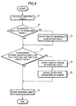
- step S2 in the flowchart shown in Fig. 4 the comparator 6 compares the detected mounting angles to the angles defining the respective permissible ranges.
- the processing advances to step S3.
- the notifying means 7 notifies the user via display monitor of the navigation device 101 or via a sound that the navigation device 101 is mounted at an angle out of the permissible range, i.e., the mounting angle is abnormal. It should be noted that the notification might advise the user to position the navigation device 101 within the permissible range.
- step S4 the comparator 6 compares the detected mounting angles ⁇ pitch, ⁇ yaw and ⁇ roll to the respective last value ⁇ pitch*, ⁇ yaw* and ⁇ roll* stored in the storage 5. In this step, if at least one of differences between the mounting angles and the respective last values exceeds a preset amount, the comparator 6 determines that the mounting angle has been changed.
- step S5 the notifying means 7 notifies the user via display monitor that the mounting angle of the navigation device 101 has been changed.
- step S6 the updating means 8 resets the learning function of the navigation device 101, thereby updating the parameters correcting the output of the acceleration sensor 1 or gyroscopic sensor 2, for example conversion gain, to the values relative to the changed mounting angles.
- the above correcting parameters are determined by the learning function of the navigation device 101.
- the aforementioned learning function determines the correcting parameter without deviation components by totalizing and averaging the amount of correction with comparing the output of the acceleration sensor 1 or gyroscopic sensor 2 to the position or map information from the GPS receiver.
- the navigation device 101 corrects the errors of the acceleration sensor 1 or gyroscopic sensor 2 occurring due to the mounting angles, by utilizing the correcting parameters.
- step 6 the updating means 8 resets the aforementioned learning function to initialize the amount of correction accumulated based on the mounting angles before change, thereby restarting the learning function relative to the changed mounting angle.
- the aforementioned learning function might be provide in the updating means 8 instead of the navigation device 101.
- the updatingmeans 8 may reset the aforementioned learning function, thereby providing the navigation device 101 with the true values.
- the true values are obtained by correcting the output of the acceleration sensor 1 and gyroscopic sensor 2 as follows.
- the updatingmeans 8 transforms the conversion gain G1 and the offset C1 for converting the output As of the acceleration sensor 1 to the true value A as expressed by the equation (6), into the values relative to the mounting angles ⁇ pitch and ⁇ yaw as expressed by the equation (7), and provides the navigation device 101 with the true value A obtained by correcting the output As of the acceleration sensor 1 based on the transformed conversion gain G1 and offset C1.
- the updating means 8 transforms the conversion gain G2 for converting the output ⁇ s of the gyroscopic sensor 2 to the true value ⁇ as expressed by the equation (8), into the values relative to the mounting angles ⁇ pitch and ⁇ roll, and provides the navigation device 101 with the true value ⁇ obtained by correcting the output ⁇ s.
- step S7 the determined mounting angles ⁇ pitch, ⁇ yaw and ⁇ roll are stored in the storage 5.
- the stored mounting angles will be used as the last values for comparison in step S4 concerning the next detecting operation.
- the mounting angle detection device detects the mounting angles ⁇ pitch, ⁇ yaw and ⁇ roll of the navigation device 101 based on the changes in the output of the acceleration sensor 1 and gyroscopic sensor 2 . Then, if any of the detectedmounting angles is out of the permissible ranges, the user is notified of the abnormality of the mounting angles. Even if the navigation device 101 is mounted at a mounting angle out of the permissible range and thus an error occurs in the displayed guidance, the user can recognize the cause and apply an appropriate remedy. Consequently, this mounting angle detection device can prevent the navigation device 101 from being mounted at a mounting angle out of the permissible range.
- this mounting angle detection device detects the change in the mounting angles by comparing the detected mounting angles to the previous mounting angles detected last time.
- the parameters for correcting the output of the sensor are updated based on the values detected this time, thereby maintaining the accuracy of the displayed guidance of the navigation device 101 even in a case where the mounting angles are changed.
- this mounting angle detection device resets and restarts the aforementioned learning function for determining the parameters when detecting the change in the mounting angle, thereby obviating the necessity for the user to reset the function and maintaining the accuracy of the displayed guidance of the navigation device 101.
- the comparator 6 might detect the abnormality and change in the mounting angles by comparing the sine value sin( ⁇ pitch) of the mounting angle in the pitch direction, the cosine value cos( ⁇ yaw) of the mounting angle in the yaw direction, and the cosine value cos( ⁇ roll) in the roll direction to the respective permissible ranges or to the respective values detected last time.
- FIG. 5 shows an block diagram representing a configuration according to this mounting angle detection device.
- the mounting angle detection device comprises a gyroscopic sensor 2, a GPS receiver 3, a gyroscopic sensor sensitivity detector 43, a storage 5, a comparator 6, notifying means 7, and updating means 8.
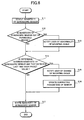
- the gyroscopic sensor sensitivity detector 43 determines the reference angular velocity ⁇ r around the pivot of the vehicle based on the amount of temporal change of the bearing in the position information from the GPS receiver 3 in step S11, and determines the ratio of the output ⁇ s of the gyroscopic sensor 2 to the reference angular velocity ⁇ r as sensitivity Sg of the gyroscopic sensor 2.
- step S12 the comparator 6 compares the aforementioned sensitivity Sg of the gyroscopic sensor 2 to the permissible range of the sensitivity.
- the permissible range is set in a range of sensitivity allowing the navigation device 101 to display accurate guidance.
- the comparator 6 determines that the mounting angles of the navigation device 101 are abnormal if the sensitivity Sg of the gyroscopic sensor 2 is out of the permissible range.
- step S13 the notifying means 7 notifies the user via the display monitor that the mounting angles of the navigation device 101 are abnormal.
- step S14 the comparator 6 compares the detected sensitivity Sg of the gyroscopic sensor 2 to the stored sensitivity Sg* determined by the last detecting operation.
- the comparator 6 determines that the mounting angles are changed if the deference between the sensitivity Sg of the gyroscopic sensor 2 and the last sensitivity Sg* stored in the storage 5 exceeds the preset amount.
- step S15 the notifying means 7 notifies the user via the displaymonitor that the mounting angles of the navigation device 101 have been changed.
- step S16 subsequent to the step S15, the updating means 8 resets the learning function for determining the parameters for correcting the output of the gyroscopic sensor 2, thereby updating the correcting parameter to those relative to the changed mounting angles.
- step S17 the determined sensitivity Sg of the gyroscopic sensor 2 is stored in the storage 5.
- the mounting angle detection device detects the sensitivity Sg of the gyroscopic sensor 2, and determines the abnormality of the mounting angles of the navigation device 101 based on the sensitivity Sg. On detection of the abnormality of the mounting angles, the user is notified of the abnormality. Even if the navigation device 101 is mounted at an improper mounting angle out of the permissible range and thus an error occurs in the displayed guidance, the user can recognize the cause and apply an appropriate remedy. Consequently, this mounting angle detection device can prevent the navigation device 101 from being mounted at an improper mounting angle.
- this mounting angle detection device detects the change of the mounting angles by comparing the detected sensitivity Sg of the gyroscopic sensor to the sensitivity Sg* detected last time. On detecting the change of the mounting angle, the mounting angle detection device resets the function for learning the correcting parameters of the sensor, and updates the correcting parameters to those relative to the changed mounting angles, thereby maintaining the accuracy of the navigation device 101, even in a case where the mounting angles have been changed.
- the present mounting angle detection device resets and restarts the aforementioned learning function for determining the parameters, thereby maintaining the accuracy of the displayed guidance of the navigation device 101 without any reset operation by the user.
Landscapes
- Engineering & Computer Science (AREA)
- Radar, Positioning & Navigation (AREA)
- Remote Sensing (AREA)
- Automation & Control Theory (AREA)
- Physics & Mathematics (AREA)
- General Physics & Mathematics (AREA)
- Navigation (AREA)
- Gyroscopes (AREA)
- Length Measuring Devices With Unspecified Measuring Means (AREA)
Abstract
Description


Claims (11)
- A mounting angle detection device for detecting a mounting angle of a vehicle-mounted device (101) mounted in a vehicle (100), comprising:wherein the mounting angle processor determines a sine value of a mounting angle in a pitch direction of the vehicle-mounted device by dividing a totalized and averaged value by acceleration of gravity, the totalized and averaged value being determined by totalizing and averaging acceleration detected by the acceleration sensor.an acceleration sensor (1) mounted in the vehicle-mounted device; anda mounting angle processor (4),
- A mounting angle detection device for detecting a mounting angle of a vehicle-mounted device (101) mounted in a vehicle (100), comprising:wherein the mounting angle processor includes:an acceleration sensor (1) and a GPS receiver (3) mounted in the vehicle-mounted device; anda mounting angle processor (4),a pitch angle processor (41) for determining a sine value of a mounting angle in a pitch direction of the vehicle-mounted device by dividing a totalized and averaged value by acceleration of gravity, the totalized and averaged value being determined by totalizing and averaging acceleration detected by the acceleration sensor; anda yaw angle processor (42) for determining a cosine value of a mounting angle in a yaw direction of the vehicle-mounted device by subtracting a product of the acceleration of gravity and the sine value of the mounting angle in the pitch direction from acceleration detected by the acceleration sensor to determine a subtracted value, and then dividing the subtracted value by a value determined by multiplying reference acceleration obtained from the GPS receiver or from a vehicle speed pulse sensor by a cosine value of the mounting angle in the pitch direction.
- A mounting angle detection device for detecting a mounting angle of a vehicle-mounted device (101) mounted in a vehicle (100), comprising:wherein the mounting angle processor includes:an acceleration sensor (1), a GPS receiver (3) and a gyroscopic sensor (2) mounted in the vehicle-mounted device; anda mounting angle processor (4),a pitch angle processor (41) for determining a sine value of a mounting angle in a pitch direction of the vehicle-mounted device by dividing a totalized and averaged value by acceleration of gravity, the totalized and averaged value being determined by totalizing and averaging acceleration detected by the acceleration sensor;a sensitivity detector (43) for determining a ratio of angular velocity detected by the gyroscopic sensor to reference angular velocity obtained from the GPS receiver as sensitivity of the gyroscopic sensor; anda roll angle processor (44) for determining a cosine value of a mounting angle in a roll direction of the vehicle-mounted device by dividing the determined sensitivity of the gyroscopic sensor by a cosine value of the mounting angle in the pitch direction.
- The device according to any one of claims 1-3, further comprising a comparator (6) for comparing the value corresponding to the mounting angle detected by the mounting angle processor to a permissible range concerning the mounting angle and then determining that themounting angle of the vehicle-mounted device is abnormal when the mounting angle is over the permissible range.
- The device according to any one of claims 1-3, further comprising a comparator (6) for comparing the value corresponding to the mounting angle determined by the mounting angle processor to a value corresponding to a mounting angle determined last time by the mounting angle processor and then determining that the mounting angle of the vehicle-mounted device has been changed when the value corresponding to the mounting angle determined by the mounting angle processor differs from the value corresponding to the mounting angle determined last time.
- The device according to claim 4, further comprising notifying means (7) for notifying that the mounting angle is abnormal when the comparator determines the abnormality.
- The device according to claim 5, further comprising updatingmeans (8) forresettingoperationofthevehicle-mounted device when the comparator determines that the mounting angle has been changed.
- A mounting angle detecting device for a vehicle-mounted device (101), comprising:a sensitivity detector (43) for determining a ratio of angular velocity detected by a gyroscopic sensor (2) mounted in the vehicle-mounted device to reference angular velocity obtained from a GPS receiver (3) mounted in the vehicle-mounted device as sensitivity of the gyroscopic sensor; anda comparator (6) for comparing the sensitivity of the gyroscopic sensor determined by the sensitivity detector to a permissible range concerning the sensitivity and then determining that themounting angle of the vehicle-mounteddevice is abnormal when the sensitivity is over the permissible range.
- A mounting angle detecting device for a vehicle-mounted device, comprising:a sensitivity detector (43) for determining a ratio of angular velocity detected by a gyroscopic sensor (2) mounted in a vehicle-mounted device (101) to reference angular velocity obtained from a GPS receiver (3) mounted in the vehicle-mounted device as sensitivity of the gyroscopic sensor; anda comparator (6) for comparing the sensitivity determined by the sensitivity detector to sensitivity determined last time by the sensitivity detector and then determining that the mounting angle of the vehicle-mounted device has been changed when the sensitivity determined by the sensitivity detector differs from the sensitivity determined last time.
- The device according to claim 8, further comprising notifying means (7) for notifying that the mounting angle is abnormal when the comparator determines the abnormality.
- The device according to claim 9, further comprising updatingmeans (8) forresettingoperationofthevehicle-mounted device when the comparator determines that the mounting angle has been changed.
Applications Claiming Priority (2)
| Application Number | Priority Date | Filing Date | Title |
|---|---|---|---|
| JP2003025783A JP4191499B2 (en) | 2003-02-03 | 2003-02-03 | In-vehicle device |
| JP2003025783 | 2003-02-03 |
Publications (3)
| Publication Number | Publication Date |
|---|---|
| EP1443307A2 true EP1443307A2 (en) | 2004-08-04 |
| EP1443307A3 EP1443307A3 (en) | 2010-10-27 |
| EP1443307B1 EP1443307B1 (en) | 2015-04-08 |
Family
ID=32652949
Family Applications (1)
| Application Number | Title | Priority Date | Filing Date |
|---|---|---|---|
| EP04002344.2A Expired - Lifetime EP1443307B1 (en) | 2003-02-03 | 2004-02-03 | Mounting angle detection device |
Country Status (3)
| Country | Link |
|---|---|
| US (1) | US20040172173A1 (en) |
| EP (1) | EP1443307B1 (en) |
| JP (1) | JP4191499B2 (en) |
Cited By (5)
| Publication number | Priority date | Publication date | Assignee | Title |
|---|---|---|---|---|
| CN102023008A (en) * | 2009-09-17 | 2011-04-20 | 索尼公司 | Angular velocity correction device, angular velocity correction method, navigation device, and cellular phone |
| WO2012075466A1 (en) * | 2010-12-03 | 2012-06-07 | Qualcomm Incorporated | Inertial sensor aided heading and positioning for gnss vehicle navigation |
| EP3176759A4 (en) * | 2015-10-23 | 2017-06-07 | LE Holdings (Beijing) Co., Ltd. | Vehicle terminal |
| CN108051839A (en) * | 2017-10-27 | 2018-05-18 | 成都天合世纪科技有限责任公司 | A kind of method of vehicle-mounted 3 D locating device and three-dimensional localization |
| IT201600127830A1 (en) * | 2016-12-19 | 2018-06-19 | Magneti Marelli Spa | Verification procedure of the installation of a device mounted on a vehicle, and relative system. |
Families Citing this family (31)
| Publication number | Priority date | Publication date | Assignee | Title |
|---|---|---|---|---|
| US7509216B2 (en) * | 2004-03-29 | 2009-03-24 | Northrop Grumman Corporation | Inertial navigation system error correction |
| JP2005297609A (en) * | 2004-04-06 | 2005-10-27 | Denso Corp | In-vehicle AV system and program |
| KR100677569B1 (en) * | 2004-12-13 | 2007-02-02 | 삼성전자주식회사 | 3D image display apparatus |
| JP4736866B2 (en) * | 2005-04-28 | 2011-07-27 | 株式会社デンソー | Navigation device |
| JP4655901B2 (en) * | 2005-11-21 | 2011-03-23 | パナソニック株式会社 | Apparatus and method for determining horizontal travel of moving object |
| JP4816339B2 (en) * | 2006-08-31 | 2011-11-16 | ソニー株式会社 | Navigation device, navigation information calculation method, and navigation information calculation program |
| JP4964047B2 (en) * | 2007-07-12 | 2012-06-27 | アルパイン株式会社 | Position detection apparatus and position detection method |
| JP4780155B2 (en) * | 2008-08-01 | 2011-09-28 | 株式会社デンソー | In-vehicle device |
| JP5736106B2 (en) * | 2009-05-19 | 2015-06-17 | 古野電気株式会社 | Moving state detection device |
| JP5482047B2 (en) * | 2009-09-15 | 2014-04-23 | ソニー株式会社 | Speed calculation device, speed calculation method, and navigation device |
| US20130006674A1 (en) | 2011-06-29 | 2013-01-03 | State Farm Insurance | Systems and Methods Using a Mobile Device to Collect Data for Insurance Premiums |
| US10977601B2 (en) | 2011-06-29 | 2021-04-13 | State Farm Mutual Automobile Insurance Company | Systems and methods for controlling the collection of vehicle use data using a mobile device |
| US9151613B2 (en) * | 2011-08-12 | 2015-10-06 | Qualcomm Incorporated | Methods and apparatus for detecting, measuring, and mitigating effects of moving an inertial navigation device's cradle |
| US9096188B2 (en) * | 2013-03-22 | 2015-08-04 | General Motors Llc | Mounting sensor and aftermarket device equipped with mounting sensor |
| US8954204B2 (en) | 2013-03-22 | 2015-02-10 | General Motors Llc | Collision sensor, collision sensing system, and method |
| JP6264173B2 (en) | 2014-04-18 | 2018-01-24 | 富士通株式会社 | Normality determination method for imaging direction, imaging device attachment state evaluation program, and imaging device attachment state evaluation device |
| JP6299373B2 (en) | 2014-04-18 | 2018-03-28 | 富士通株式会社 | Imaging direction normality determination method, imaging direction normality determination program, and imaging direction normality determination apparatus |
| JP6299371B2 (en) | 2014-04-18 | 2018-03-28 | 富士通株式会社 | Imaging direction inclination detection method, imaging direction inclination detection program, and imaging direction inclination detection apparatus |
| US9360322B2 (en) | 2014-05-15 | 2016-06-07 | State Farm Mutual Automobile Insurance Company | System and method for separating ambient gravitational acceleration from a moving three-axis accelerometer data |
| US10019762B2 (en) | 2014-05-15 | 2018-07-10 | State Farm Mutual Automobile Insurance Company | System and method for identifying idling times of a vehicle using accelerometer data |
| US9786103B2 (en) | 2014-05-15 | 2017-10-10 | State Farm Mutual Automobile Insurance Company | System and method for determining driving patterns using telematics data |
| US10304138B2 (en) | 2014-05-15 | 2019-05-28 | State Farm Mutual Automobile Insurance Company | System and method for identifying primary and secondary movement using spectral domain analysis |
| US9127946B1 (en) | 2014-05-15 | 2015-09-08 | State Farm Mutual Automobile Insurance Company | System and method for identifying heading of a moving vehicle using accelerometer data |
| JP6191580B2 (en) * | 2014-10-28 | 2017-09-06 | トヨタ自動車株式会社 | Sensor calibration method for moving objects |
| CN108399757B (en) * | 2018-04-16 | 2021-06-18 | 宁波赛奥零点智能科技有限公司 | A tamper-proof method for safety monitoring of battery car |
| WO2020186406A1 (en) * | 2019-03-15 | 2020-09-24 | 深圳市大疆创新科技有限公司 | Self-correcting method for mounting angle of sensor, sensor, and mobile device |
| US11709279B2 (en) | 2019-08-14 | 2023-07-25 | Apple Inc. | Device orientation initialization |
| CN112525143B (en) * | 2019-09-19 | 2022-09-27 | 北京魔门塔科技有限公司 | Method for determining installation angle of equipment and vehicle-mounted terminal |
| CN113074757B (en) * | 2021-04-08 | 2023-08-22 | 北京李龚导航科技有限公司 | Calibration method of installation error angle of vehicle inertial navigation |
| CN113155171B (en) * | 2021-04-08 | 2025-05-16 | 上海三菱电梯有限公司 | Sensor installation status self-checking method and sensor for realizing installation status self-checking |
| JP2024041548A (en) | 2022-09-14 | 2024-03-27 | アルプスアルパイン株式会社 | autonomous navigation system |
Family Cites Families (9)
| Publication number | Priority date | Publication date | Assignee | Title |
|---|---|---|---|---|
| JPH04238216A (en) * | 1991-01-23 | 1992-08-26 | Sumitomo Electric Ind Ltd | How to calculate the gyro scale factor |
| CN1090314C (en) * | 1995-08-28 | 2002-09-04 | 数据技术株式会社 | Mobile detection device |
| JP2843904B2 (en) * | 1996-03-04 | 1999-01-06 | 防衛庁技術研究本部長 | Inertial navigation system for vehicles |
| AU7099398A (en) * | 1997-04-01 | 1998-10-22 | Kelsey-Hayes Company | Mounting structure for an acceleration sensor |
| JP3375268B2 (en) * | 1997-05-27 | 2003-02-10 | 株式会社日立製作所 | Navigation device |
| US6091359A (en) * | 1997-07-14 | 2000-07-18 | Motorola, Inc. | Portable dead reckoning system for extending GPS coverage |
| US6028975A (en) * | 1998-01-13 | 2000-02-22 | Sun Microsystems, Inc. | Low thermal skew fiber optic cable |
| US6417767B1 (en) * | 2000-03-27 | 2002-07-09 | Craig D. Carlson | Device and system for indicating rapid deceleration in vehicles |
| TW561262B (en) * | 2001-10-19 | 2003-11-11 | Yamaha Motor Co Ltd | Tipping detecting device for a motorcycle |
-
2003
- 2003-02-03 JP JP2003025783A patent/JP4191499B2/en not_active Expired - Fee Related
-
2004
- 2004-02-02 US US10/768,654 patent/US20040172173A1/en not_active Abandoned
- 2004-02-03 EP EP04002344.2A patent/EP1443307B1/en not_active Expired - Lifetime
Cited By (9)
| Publication number | Priority date | Publication date | Assignee | Title |
|---|---|---|---|---|
| CN102023008A (en) * | 2009-09-17 | 2011-04-20 | 索尼公司 | Angular velocity correction device, angular velocity correction method, navigation device, and cellular phone |
| WO2012075466A1 (en) * | 2010-12-03 | 2012-06-07 | Qualcomm Incorporated | Inertial sensor aided heading and positioning for gnss vehicle navigation |
| US9803983B2 (en) | 2010-12-03 | 2017-10-31 | Qualcomm Incorporated | Inertial sensor aided heading and positioning for GNSS vehicle navigation |
| US9816818B2 (en) | 2010-12-03 | 2017-11-14 | Qualcomm Incorporated | Inertial sensor aided heading and positioning for GNSS vehicle navigation |
| US9891054B2 (en) | 2010-12-03 | 2018-02-13 | Qualcomm Incorporated | Inertial sensor aided heading and positioning for GNSS vehicle navigation |
| EP3176759A4 (en) * | 2015-10-23 | 2017-06-07 | LE Holdings (Beijing) Co., Ltd. | Vehicle terminal |
| IT201600127830A1 (en) * | 2016-12-19 | 2018-06-19 | Magneti Marelli Spa | Verification procedure of the installation of a device mounted on a vehicle, and relative system. |
| EP3336488A1 (en) * | 2016-12-19 | 2018-06-20 | Magneti Marelli S.p.A. | Method of verification of the installation of an apparatus mounted on board a vehicle, and related system |
| CN108051839A (en) * | 2017-10-27 | 2018-05-18 | 成都天合世纪科技有限责任公司 | A kind of method of vehicle-mounted 3 D locating device and three-dimensional localization |
Also Published As
| Publication number | Publication date |
|---|---|
| JP4191499B2 (en) | 2008-12-03 |
| JP2004239613A (en) | 2004-08-26 |
| EP1443307B1 (en) | 2015-04-08 |
| EP1443307A3 (en) | 2010-10-27 |
| US20040172173A1 (en) | 2004-09-02 |
Similar Documents
| Publication | Publication Date | Title |
|---|---|---|
| EP1443307B1 (en) | Mounting angle detection device | |
| JP4739378B2 (en) | Mounting angle detector | |
| US8185308B2 (en) | Angular velocity correcting device, angular velocity correcting method, and navigation device | |
| US7230567B2 (en) | Azimuth/attitude detecting sensor | |
| EP2040037A2 (en) | Navigation device | |
| EP2249172A1 (en) | Satellite navigation/dead-reckoning navigation integrated positioning device | |
| EP1913337B1 (en) | Self-calibration for an inertial instrument based on real time bias estimator | |
| EP2270431A2 (en) | An inertial navigation system with error correction based on navigation map | |
| WO2000017607A9 (en) | Calibration of multi-axis accelerometer in vehicle navigation system | |
| US8108140B2 (en) | Navigation device | |
| JPH10307032A (en) | Navigator | |
| JP3402383B2 (en) | Vehicle current position detection device | |
| EP2831599B1 (en) | Inertial sensor enhancement | |
| EP1260790A2 (en) | Method of and apparatus for detecting angular velocity, method of and apparatus for detecting angle, navigation system and computer program therefor | |
| KR100586894B1 (en) | Determination method of vehicle's stationary state, vehicle navigation information generation method and vehicle navigation system | |
| JP2711746B2 (en) | Angular velocity measuring device | |
| JP2015004593A (en) | Navigation device | |
| JP3331865B2 (en) | Navigation device | |
| US12111159B2 (en) | Azimuth estimation device | |
| JPH102747A (en) | Navigation device | |
| JP2006071473A (en) | Zero point error detection device for angular velocity sensor and method for the same | |
| JP4808131B2 (en) | Stop determination method | |
| KR100814291B1 (en) | Device for providing location information using GPS and sensor | |
| KR102219175B1 (en) | Apparatus for determining mounting angle of product in a vehicle | |
| JP2020134460A (en) | Gyro sensor correction system, gyro sensor correction method and processing device |
Legal Events
| Date | Code | Title | Description |
|---|---|---|---|
| PUAI | Public reference made under article 153(3) epc to a published international application that has entered the european phase |
Free format text: ORIGINAL CODE: 0009012 |
|
| AK | Designated contracting states |
Kind code of ref document: A2 Designated state(s): AT BE BG CH CY CZ DE DK EE ES FI FR GB GR HU IE IT LI LU MC NL PT RO SE SI SK TR |
|
| AX | Request for extension of the european patent |
Extension state: AL LT LV MK |
|
| PUAL | Search report despatched |
Free format text: ORIGINAL CODE: 0009013 |
|
| AK | Designated contracting states |
Kind code of ref document: A3 Designated state(s): AT BE BG CH CY CZ DE DK EE ES FI FR GB GR HU IE IT LI LU MC NL PT RO SE SI SK TR |
|
| AX | Request for extension of the european patent |
Extension state: AL LT LV MK |
|
| PUAF | Information related to the publication of a search report (a3 document) modified or deleted |
Free format text: ORIGINAL CODE: 0009199SEPU |
|
| PUAL | Search report despatched |
Free format text: ORIGINAL CODE: 0009013 |
|
| D17D | Deferred search report published (deleted) | ||
| AK | Designated contracting states |
Kind code of ref document: A3 Designated state(s): AT BE BG CH CY CZ DE DK EE ES FI FR GB GR HU IE IT LI LU MC NL PT RO SE SI SK TR |
|
| AX | Request for extension of the european patent |
Extension state: AL LT LV MK |
|
| RAP1 | Party data changed (applicant data changed or rights of an application transferred) |
Owner name: PIONEER CORPORATION |
|
| 17P | Request for examination filed |
Effective date: 20110117 |
|
| 17Q | First examination report despatched |
Effective date: 20110302 |
|
| AKX | Designation fees paid |
Designated state(s): DE FR GB |
|
| RIC1 | Information provided on ipc code assigned before grant |
Ipc: G01C 25/00 20060101AFI20140624BHEP |
|
| GRAP | Despatch of communication of intention to grant a patent |
Free format text: ORIGINAL CODE: EPIDOSNIGR1 |
|
| RIC1 | Information provided on ipc code assigned before grant |
Ipc: G01C 21/26 20060101AFI20140819BHEP |
|
| INTG | Intention to grant announced |
Effective date: 20140910 |
|
| GRAS | Grant fee paid |
Free format text: ORIGINAL CODE: EPIDOSNIGR3 |
|
| GRAA | (expected) grant |
Free format text: ORIGINAL CODE: 0009210 |
|
| AK | Designated contracting states |
Kind code of ref document: B1 Designated state(s): DE FR GB |
|
| REG | Reference to a national code |
Ref country code: GB Ref legal event code: FG4D |
|
| REG | Reference to a national code |
Ref country code: DE Ref legal event code: R084 Ref document number: 602004046937 Country of ref document: DE |
|
| REG | Reference to a national code |
Ref country code: DE Ref legal event code: R096 Ref document number: 602004046937 Country of ref document: DE Effective date: 20150513 |
|
| REG | Reference to a national code |
Ref country code: DE Ref legal event code: R084 Ref document number: 602004046937 Country of ref document: DE Effective date: 20150422 Ref country code: GB Ref legal event code: 746 Effective date: 20150507 |
|
| REG | Reference to a national code |
Ref country code: DE Ref legal event code: R097 Ref document number: 602004046937 Country of ref document: DE |
|
| PLBE | No opposition filed within time limit |
Free format text: ORIGINAL CODE: 0009261 |
|
| STAA | Information on the status of an ep patent application or granted ep patent |
Free format text: STATUS: NO OPPOSITION FILED WITHIN TIME LIMIT |
|
| REG | Reference to a national code |
Ref country code: FR Ref legal event code: PLFP Year of fee payment: 13 |
|
| 26N | No opposition filed |
Effective date: 20160111 |
|
| REG | Reference to a national code |
Ref country code: FR Ref legal event code: PLFP Year of fee payment: 14 |
|
| REG | Reference to a national code |
Ref country code: FR Ref legal event code: PLFP Year of fee payment: 15 |
|
| PGFP | Annual fee paid to national office [announced via postgrant information from national office to epo] |
Ref country code: GB Payment date: 20221230 Year of fee payment: 20 |
|
| PGFP | Annual fee paid to national office [announced via postgrant information from national office to epo] |
Ref country code: FR Payment date: 20230110 Year of fee payment: 20 |
|
| PGFP | Annual fee paid to national office [announced via postgrant information from national office to epo] |
Ref country code: DE Payment date: 20221229 Year of fee payment: 20 |
|
| REG | Reference to a national code |
Ref country code: DE Ref legal event code: R071 Ref document number: 602004046937 Country of ref document: DE |
|
| REG | Reference to a national code |
Ref country code: GB Ref legal event code: PE20 Expiry date: 20240202 |
|
| PG25 | Lapsed in a contracting state [announced via postgrant information from national office to epo] |
Ref country code: GB Free format text: LAPSE BECAUSE OF EXPIRATION OF PROTECTION Effective date: 20240202 |