EP1913337B1 - Self-calibration for an inertial instrument based on real time bias estimator - Google Patents
Self-calibration for an inertial instrument based on real time bias estimator Download PDFInfo
- Publication number
- EP1913337B1 EP1913337B1 EP06771696A EP06771696A EP1913337B1 EP 1913337 B1 EP1913337 B1 EP 1913337B1 EP 06771696 A EP06771696 A EP 06771696A EP 06771696 A EP06771696 A EP 06771696A EP 1913337 B1 EP1913337 B1 EP 1913337B1
- Authority
- EP
- European Patent Office
- Prior art keywords
- signals
- bias
- inertial
- bias correction
- measb
- Prior art date
- Legal status (The legal status is an assumption and is not a legal conclusion. Google has not performed a legal analysis and makes no representation as to the accuracy of the status listed.)
- Active
Links
Images

Classifications
-
- G—PHYSICS
- G01—MEASURING; TESTING
- G01C—MEASURING DISTANCES, LEVELS OR BEARINGS; SURVEYING; NAVIGATION; GYROSCOPIC INSTRUMENTS; PHOTOGRAMMETRY OR VIDEOGRAMMETRY
- G01C21/00—Navigation; Navigational instruments not provided for in groups G01C1/00 - G01C19/00
- G01C21/10—Navigation; Navigational instruments not provided for in groups G01C1/00 - G01C19/00 by using measurements of speed or acceleration
- G01C21/12—Navigation; Navigational instruments not provided for in groups G01C1/00 - G01C19/00 by using measurements of speed or acceleration executed aboard the object being navigated; Dead reckoning
- G01C21/16—Navigation; Navigational instruments not provided for in groups G01C1/00 - G01C19/00 by using measurements of speed or acceleration executed aboard the object being navigated; Dead reckoning by integrating acceleration or speed, i.e. inertial navigation
- G01C21/183—Compensation of inertial measurements, e.g. for temperature effects
-
- G—PHYSICS
- G01—MEASURING; TESTING
- G01C—MEASURING DISTANCES, LEVELS OR BEARINGS; SURVEYING; NAVIGATION; GYROSCOPIC INSTRUMENTS; PHOTOGRAMMETRY OR VIDEOGRAMMETRY
- G01C25/00—Manufacturing, calibrating, cleaning, or repairing instruments or devices referred to in the other groups of this subclass
Definitions
- This invention relates to inertial instruments, such as gyroscopes and accelerometers, and more specifically to bias error correction in such instruments.
- bias a measure of the deviation of a measurement made by a non-ideal inertial instrument from a measurement made by a perfect or ideal instrument.
- the bias of a gyroscope is determined by the difference between the gyroscope's reading at a zero angular rate and zero which would be measured by a perfect gyroscope.
- Bias drift is a rate of change of the bias resulting from changes such as environmental conditions over time.
- One method of compensation for bias and/or bias drift in an inertial instrument is to periodically make bias correction adjustments of the inertial instrument based on information obtained from another source of known accuracy.
- GPS global positioning satellite
- a GPS receiver co-located with the inertial instrument can be used to determine a series of locations over known time intervals. This GPS information can be utilized to periodically recalibrate a bias error correction signal of the inertial instrument to make the output coincide with the GPS data.
- GPS global positioning satellite
- US-A-5 012 424 describes an inertial measurement apparatus comprising first and second inertial instruments; means for combining first and second bias error signals with the sensed signals; a bias estimator for receiving the output signals, for generating first and second bias correction signals and for generating first and second corrected output signals based on a combination of the first and second bias correction signals.
- An exemplary inertial measurement apparatus incorporates self-calibrating bias correction signals.
- First and second inertial instruments generate respective input signals representative of an inertial attribute to be measured.
- a bias estimator generates first and second bias correction signals.
- First and second summation nodes receive the respective input signals and the respective first and second bias correction signals.
- the first and second summation nodes produce respective summed signals that are coupled to the first and second inertial instruments.
- the first and second inertial instruments generate respective output signals representative of a value of the inertial attribute based on the respective summed signals.
- the bias estimator calculates the first and second bias correction signals based on first and second measurements made during respective first and second time intervals where a sign of one of the first and second bias error signals is changed from one state during the first time interval to the other state during the second time interval.
- An exemplary method implements steps as generally described above with regard to the exemplary inertial measurement apparatus.
- One aspect of the present invention resides in the recognition of the difficulties associated with bias compensation of an inertial instrument where the compensation relies upon information that must be obtained from another source of known accuracy. Part of the recognition includes an appreciation that operating conditions of vehicles containing the inertial instrument often make obtaining information from an external source of known accuracy difficult or impossible.
- the exemplary self-calibrating inertial instrument in accordance with the present invention was created to overcome such difficulties.
- self-calibrating refers to the ability of an inertial instrument apparatus to provide its own bias corrections without requiring an input based on an external source of information of known accuracy.
- occasional calibrations from external sources can be utilized to confirm or reset calibration of the inertial instrument.
- FIG. 1 is an exemplary graph showing bias signal error polarities 10 and 12 associated with gyroscopes A and B, respectively.
- gyroscopes are used in the described exemplary implementation, it will be apparent that any type of inertial instrument, e.g. gyroscope, accelerometer, etc., will benefit from the improvements as will be understood from the following explanation.
- the bias error signals provide the means for error correction for the gyroscopes so with the outputs from the gyroscopes will more accurately represent the attribute being sensed based on inputs received by the gyroscopes.
- Each of bias error signals 10 and 12 have two states, normal and reversed, which correspond to the sign relationship between the sensed input value of the gyroscope and the bias error signal.
- a + relationship represents that the bias signal is added to the sensed input signal and a - relationship represents that the bias signal is subtracted from the sensed input signal.
- the "normal” relationship can be either in a + or - relationship depending upon the type of error correction to be implemented.
- the "reversed” relationship represents the opposite sign from the normal relationship. In this example, normal and reversed correspond to a + and - relationship, respectively.
- the graph represents four different measurement intervals, Meas 1 - Meas 4. Each measurement interval represents one of the four different state combinations of the bias error signals 10 and 12. Each bias error signal has two states, normal and reversed. During the operation of the gyroscopes A and B, the respective bias error signals 10 and 12 can be sequenced between normal and reversed conditions so that all four different state combinations represented by the four different measurement intervals occur. Depending upon the particular application and the sampling time at which the outputs of the gyroscopes are utilized, the rate of the sequencing can be adjusted to meet the particular application. As will be explained in more detail below, information obtained during two measurement intervals is utilized as part of the self-calibration process and hence the rate of sequencing will define the maximum rate at which new calibration information can be calculated. Although it may be desirable to sequence through all four combinations of states as shown in FIG. 1 with corresponding calculations for bias error, two time intervals with a change of sign of one of the two bias signals will yield sufficient information to make a bias error calculation.
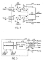
- FIG. 2 is an exemplary block diagram of an illustrative embodiment of a self-calibrating inertial instrument in accordance with the present invention.
- Inertial instruments 20 and 22 receive respective input signals 28 and 34 representing the attribute to be measured.
- the attribute being measured by the gyroscopes is angular position such as measured in degrees.
- this diagram is provided to assist in explanation of the operation of an embodiment of the present invention and does not identically correspond to physical structure.
- inputs 24 and 26 will normally be generated by devices within the inertial instruments.
- the inertial instruments 20 and 22 are oriented relative to each other to share a common axis or plane 21 relative to the attribute being measured.
- each gyroscope (assuming each was a perfect gyroscope) would produce an output with the same value in degrees.
- the input 24 is a combination of a sensed input signal 28 combined with a bias signal 48 (BiasA) by summation node 54.
- input 26 is a combination of a sensed input signal 34 combined with a bias signal 50 (BiasB) by summation node 52.
- the bias signals 30 and 36 are utilized to provide error correction resulting in more accurate outputs 40 and 42 by inertial instruments 20 and 22, respectively.
- a bias estimator 44 receives the inputs 24 (MeasA) and 26 (MeasB) as well as the outputs 40 and 42.
- the bias generator generates the error correction bias signals 30 and 36. It also generates a computed output value 46 that may comprise output 40, output 42, or combination of outputs 40 and 42 as will be explained below.
- FIG. 2 do not have to be implemented as discrete components.
- two separate inertial instruments could each contain all of the necessary components with the required information being shared between respective bias estimators contained in each inertial instrument.
- all of the required functions could be contained in a single integrated device which would contain functionality for two inertial instruments and the bias estimator.
- the bias errors may be directly observable if two instruments, gyroscopes (gyros) in this exemplary embodiment, are located along the same axis relative to the attribute being sensed and are sequenced as described. Both gyros are operating stabilized over each of the measurement intervals Meas 1 through Meas 4. Both gyros sense rotations about the same axis.
- gyroscopes gyros
- Both gyros sense rotations about the same axis.
- a digital implementation will contain counts, i.e. numerical values, corresponding to inputs and outputs of the inertial instrument measurements from two parallel instrument inputs/channels Win(A) and Win(B). These inputs will have been compensated for any scale factor differences that may exist between the two gyros.
- the bias estimator 44 preferably processes the required inputs and generates outputs in substantially real time.
- the bias estimator supports a self-biasing function and computes values for bias signals 30 and 36 in accordance with the above description.
- a filter which may comprise part of the bias estimator, is preferably used to compute smoothed values of bias signals 30 and 36 such as by computing an average over several samples.
- Bias compensated measurements Wout(A) and Wout(B) comprise system inertial measurement data/values that are supplied to external devices for use in calculating other functions/parameters.
- output Wout(C) which may be computed by the bias estimator, is preferably supplied to the external devices.
- Output Wout(C) is an average of Wout(A) and Wout(B) when both are available, i.e. when neither is in a bias polarity transition period as exists between the measurement intervals, and uses only one of Wout(A) and Wout(B) when the other is in a bias polarity transition period.
- FIG. 3 is a block diagram of an exemplary bias estimator 44.
- a microprocessor 62 is supported by read-only memory (ROM) 64 and a random access memory (RAM) 66.
- Microprocessor 62 is coupled to an input/output module 68 that supports receiving and transmitting digital signals as shown.
- the microprocessor 62 operates under stored program control instructions preferably contained initially in ROM 64. Operational instructions as well as data are stored in RAM 66 for processing by microprocessor 62.
- ROM 64 read-only memory
- RAM random access memory
- the summation points 32 and 38 are implemented by software running on microprocessor 62, and the "Gyro A" and “Gyro B” of FIG. 3 include the summation points 54 and 52, respectively, as shown in FIG. 2 .
- the functions and calculations can be implemented in an application specific integrated circuit or other form of hardware implementation.
- additional functionality required by the inertial instruments could be incorporated into a single device.
Abstract
Description
- This invention relates to inertial instruments, such as gyroscopes and accelerometers, and more specifically to bias error correction in such instruments.
- The performance of inertial instruments is degraded by bias, a measure of the deviation of a measurement made by a non-ideal inertial instrument from a measurement made by a perfect or ideal instrument. For example, the bias of a gyroscope is determined by the difference between the gyroscope's reading at a zero angular rate and zero which would be measured by a perfect gyroscope. Bias drift is a rate of change of the bias resulting from changes such as environmental conditions over time.
- One method of compensation for bias and/or bias drift in an inertial instrument is to periodically make bias correction adjustments of the inertial instrument based on information obtained from another source of known accuracy. For example, global positioning satellite (GPS) signals processed by a GPS receiver co-located with the inertial instrument can be used to determine a series of locations over known time intervals. This GPS information can be utilized to periodically recalibrate a bias error correction signal of the inertial instrument to make the output coincide with the GPS data. However, depending upon the operational environment, the reception of GPS signals is not always possible, and hence correction of the inertial instrument's output based on GPS data cannot always be relied upon. Therefore, a need exists to minimize bias and bias drift in an inertial instrument without requiring a separate source of accurate positional information such as derived from GPS information or the like.
US-A-5 012 424 describes an inertial measurement apparatus comprising first and second inertial instruments; means for combining first and second bias error signals with the sensed signals; a bias estimator for receiving the output signals, for generating first and second bias correction signals and for generating first and second corrected output signals based on a combination of the first and second bias correction signals. - It is an object of the present invention to satisfy this need.
- An exemplary inertial measurement apparatus incorporates self-calibrating bias correction signals. First and second inertial instruments generate respective input signals representative of an inertial attribute to be measured. A bias estimator generates first and second bias correction signals. First and second summation nodes receive the respective input signals and the respective first and second bias correction signals. The first and second summation nodes produce respective summed signals that are coupled to the first and second inertial instruments. The first and second inertial instruments generate respective output signals representative of a value of the inertial attribute based on the respective summed signals. The bias estimator calculates the first and second bias correction signals based on first and second measurements made during respective first and second time intervals where a sign of one of the first and second bias error signals is changed from one state during the first time interval to the other state during the second time interval.
- An exemplary method implements steps as generally described above with regard to the exemplary inertial measurement apparatus.
- Features of exemplary implementations of the invention will become apparent from the description, the claims, and the accompanying drawings in which:
-
FIG. 1 is a graph illustrating the polarity of bias signals for two exemplary gyroscopes. -
FIG. 2 is a representative diagram of an exemplary embodiment of the present invention. -
FIG. 3 is a block diagram of the exemplary bias estimator as shown inFIG. 2 . - One aspect of the present invention resides in the recognition of the difficulties associated with bias compensation of an inertial instrument where the compensation relies upon information that must be obtained from another source of known accuracy. Part of the recognition includes an appreciation that operating conditions of vehicles containing the inertial instrument often make obtaining information from an external source of known accuracy difficult or impossible. The exemplary self-calibrating inertial instrument in accordance with the present invention was created to overcome such difficulties. As used herein "self-calibrating" refers to the ability of an inertial instrument apparatus to provide its own bias corrections without requiring an input based on an external source of information of known accuracy. However, it will be appreciated that occasional calibrations from external sources can be utilized to confirm or reset calibration of the inertial instrument.
-
FIG. 1 is an exemplary graph showing biassignal error polarities - Each of
bias error signals - The graph represents four different measurement intervals, Meas 1 -
Meas 4. Each measurement interval represents one of the four different state combinations of thebias error signals bias error signals FIG. 1 with corresponding calculations for bias error, two time intervals with a change of sign of one of the two bias signals will yield sufficient information to make a bias error calculation. -
FIG. 2 is an exemplary block diagram of an illustrative embodiment of a self-calibrating inertial instrument in accordance with the present invention. As used herein, the same reference numeral may be utilized to refer to an input line as well as the input signal carried by the line; the appropriate meaning will be clear from the context.Inertial instruments respective input signals inputs inertial instruments plane 21 relative to the attribute being measured. Thus, if theinertial instruments - The
input 24 is a combination of a sensedinput signal 28 combined with a bias signal 48 (BiasA) bysummation node 54. Similarly,input 26 is a combination of a sensedinput signal 34 combined with a bias signal 50 (BiasB) bysummation node 52. Thebias signals accurate outputs inertial instruments bias estimator 44 receives the inputs 24 (MeasA) and 26 (MeasB) as well as theoutputs output value 46 that may compriseoutput 40,output 42, or combination ofoutputs - The elements shown in
FIG. 2 do not have to be implemented as discrete components. For example, two separate inertial instruments could each contain all of the necessary components with the required information being shared between respective bias estimators contained in each inertial instrument. Alternatively, all of the required functions could be contained in a single integrated device which would contain functionality for two inertial instruments and the bias estimator. - The bias errors may be directly observable if two instruments, gyroscopes (gyros) in this exemplary embodiment, are located along the same axis relative to the attribute being sensed and are sequenced as described. Both gyros are operating stabilized over each of the
measurement intervals Meas 1 throughMeas 4. Both gyros sense rotations about the same axis. The measurements MeasA and MeasB made by gyros A and B during each ith measurement interval are:

For the first and second intervals,


Or (Eq7):
Which is of the form:
The [H] matrix is non singular as indicated by (Eq9):
The four variables, Win(1), Win(2), BiasA and BiasB are therefore individually observable:
Expanded in Eq 11 as:
- With regard to the illustrative embodiment, a digital implementation will contain counts, i.e. numerical values, corresponding to inputs and outputs of the inertial instrument measurements from two parallel instrument inputs/channels Win(A) and Win(B). These inputs will have been compensated for any scale factor differences that may exist between the two gyros. The
bias estimator 44 preferably processes the required inputs and generates outputs in substantially real time. The bias estimator supports a self-biasing function and computes values for bias signals 30 and 36 in accordance with the above description. A filter, which may comprise part of the bias estimator, is preferably used to compute smoothed values of bias signals 30 and 36 such as by computing an average over several samples. Bias compensated measurements Wout(A) and Wout(B) comprise system inertial measurement data/values that are supplied to external devices for use in calculating other functions/parameters. Also output Wout(C), which may be computed by the bias estimator, is preferably supplied to the external devices. Output Wout(C) is an average of Wout(A) and Wout(B) when both are available, i.e. when neither is in a bias polarity transition period as exists between the measurement intervals, and uses only one of Wout(A) and Wout(B) when the other is in a bias polarity transition period. - The above implementation, described in terms of a gyroscope, is equally applicable to a pair of parallel accelerometers having the same reversibility between sensed input and bias error.
-
FIG. 3 is a block diagram of anexemplary bias estimator 44. Amicroprocessor 62 is supported by read-only memory (ROM) 64 and a random access memory (RAM) 66.Microprocessor 62 is coupled to an input/output module 68 that supports receiving and transmitting digital signals as shown. Themicroprocessor 62 operates under stored program control instructions preferably contained initially inROM 64. Operational instructions as well as data are stored inRAM 66 for processing bymicroprocessor 62. Those skilled in the art will understand how to provide appropriate control instructions formicroprocessor 62 in order to implement the functions and calculations discussed above. ComparingFIGs. 2 and 3 , the summation points 32 and 38 are implemented by software running onmicroprocessor 62, and the "Gyro A" and "Gyro B" ofFIG. 3 include the summation points 54 and 52, respectively, as shown inFIG. 2 . Alternatively, the functions and calculations can be implemented in an application specific integrated circuit or other form of hardware implementation. In addition to the functionality and calculations required by the bias estimator, additional functionality required by the inertial instruments could be incorporated into a single device. - The scope of the invention is defined in the following claims,
Claims (9)
- An inertial measurement apparatus comprising:first and second means (20,22) for generating respective sensed signals (28,34) representative of an inertial attribute to be measured;means (52,54) adapted to combine first and second bias error signals (48,50) with the respective sensed signals thereby generating respective output signals (24,26);bias estimator means (44), adapted to receive said output signals, for generating respective first and second bias correction signals (30,36) corresponding to the first and second means;the bias estimator means adapted to calculate the first and second bias correction signals based on first and second measurements made during respective first and second time intervals where a sign of one of the first and second bias error signals changes from one state during the first time interval to the other stateduring the second time interval;the bias estimator means adapted to generate first and second corrected output signals (40,42) based on a combination of the first and second bias correction signals with the respective output signals.
- The apparatus of claim 1 wherein the bias estimator means calculates the first and second bias correction signals based on first and second measurements made during respective first and second time intervals where a sign of the other of the first and second bias correction signals does not change state during the first and second time intervals.
- The apparatus of claim 2 wherein the bias estimator means calculates the first and second bias correction signals based on the following equations:


where WinA(1) and WinB(1) are the first and second respective sensed signals measured during the first time interval and WinA(2) and WinB(2) are the first and second respective sensed signals measured during the second time interval, and BiasA and Bias B are the first and second bias error signals, and where MeasA(I), MeasB(I), MeasA(2) and MeasB(2) are the first and second measurements made during respective first and second time intervals. - The apparatus of any preceding claim, wherein the first and second means each comprise inertial instruments that have the same physical orientation relative to the inertial attribute to be measured, so that the first and second means are measuring the same inertial attribute.
- The apparatus of any preceding claim wherein the bias estimator means generates a third corrected output signal (46) representative of a value of the inertial attribute, where the third output signal is an average of the respective output signals of the first and second means when the sign of neither of the first and second bias correction signals is changing, the third corrected output signal being selected to represent the inertial attribute of one of the first and second means when the other of the first and second means has a respective bias correction signal with its sign undergoing a change of states.
- A method for utilizing self-calibrating bias signals in an inertial measurement apparatus comprising: generating first and second sensed signals (28,34) each representative of a same inertial attribute to be determined, where each of the first and second sensed signals is generated based on the same parameters sensed at the same location; combining first and second bias error signals (48,50) with the respective first and second sensed signals to generate respective first and second output signals (24,26), generating first and second bias correction signals (30,36) that correspond to the respective first and second output signals; calculating the first and second bias correction signals based on measurements made during first and second time intervals where a sign of the first bias error signal (30) is changed from one state during the first time interval to another state during the second time interval generating first and second corrected output signals (40,42) representative of a value of the inertial attribute based on the first and second output signals and the first and second bias correction signals, respectively.
- The method of claim 6 wherein the calculating step comprises calculating the first and second bias correction signals based on first and second measurements made during respective first and second time intervals where a sign of the second bias correction signal does not change state during the first and second time intervals.
- The method of claim 7 wherein the calculating step comprises calculating the first bias correction signal based on the following equations:


where WinA(1) and WinB(1) are the first and second respective sensed signals measured during the first time interval and WinA(2) and WinB(2) are the first and second respective sensed signals measured during the second time interval, and BiasA and Bias B are the first and second bias error signals, and where MeasA(I), MeasB(I), MeasA(2) and MeasB(2) are the first and second measurements made during respective first and second time intervals. - The method of claim 8 further comprising the step of generating a third corrected output signal (46) representative of a value of the inertial attribute, where the third corrected output signal is an average of the first and second corrected output signals when the sign of neither of the first and second bias correction signals is changing, the third corrected output signal being selected to represent the inertial attribute of one of the first and second corrected outputs when the other of the of the first and second corrected output signals has a corresponding bias correction signal with its sign undergoing a change of state.
Applications Claiming Priority (3)
| Application Number | Priority Date | Filing Date | Title |
|---|---|---|---|
| US70662805P | 2005-08-08 | 2005-08-08 | |
| US11/364,316 US7103477B1 (en) | 2005-08-08 | 2006-02-28 | Self-calibration for an inertial instrument based on real time bias estimator |
| PCT/US2006/021064 WO2007018689A1 (en) | 2005-08-08 | 2006-05-31 | Self-calibration for an inertial instrument based on real time bias estimator |
Publications (2)
| Publication Number | Publication Date |
|---|---|
| EP1913337A1 EP1913337A1 (en) | 2008-04-23 |
| EP1913337B1 true EP1913337B1 (en) | 2009-07-01 |
Family
ID=36939577
Family Applications (1)
| Application Number | Title | Priority Date | Filing Date |
|---|---|---|---|
| EP06771696A Active EP1913337B1 (en) | 2005-08-08 | 2006-05-31 | Self-calibration for an inertial instrument based on real time bias estimator |
Country Status (6)
| Country | Link |
|---|---|
| US (1) | US7103477B1 (en) |
| EP (1) | EP1913337B1 (en) |
| JP (1) | JP5243956B2 (en) |
| AT (1) | ATE435416T1 (en) |
| DE (1) | DE602006007589D1 (en) |
| WO (1) | WO2007018689A1 (en) |
Families Citing this family (19)
| Publication number | Priority date | Publication date | Assignee | Title |
|---|---|---|---|---|
| US7739896B2 (en) * | 2007-03-15 | 2010-06-22 | Northrop Grumman Guidance And Electronics Company, Inc. | Self-calibration of scale factor for dual resonator class II coriolis vibratory gyros |
| US7640786B2 (en) | 2007-03-28 | 2010-01-05 | Northrop Grumman Guidance And Electronics Company, Inc. | Self-calibrating accelerometer |
| US7698082B2 (en) * | 2008-05-20 | 2010-04-13 | Northrop Grumman Guidance And Electronics Company, Inc. | Real time error determination for inertial instruments |
| US8446143B2 (en) * | 2008-06-27 | 2013-05-21 | National Instruments Corporation | Self-calibration circuit with gyrated output impedance |
| KR101008360B1 (en) * | 2008-07-01 | 2011-01-14 | (주)마이크로인피니티 | Appratus and method of calibration of a gyro sensor in a mobile robot. |
| US7912664B2 (en) * | 2008-09-11 | 2011-03-22 | Northrop Grumman Guidance And Electronics Company, Inc. | Self calibrating gyroscope system |
| US8146401B2 (en) * | 2008-09-17 | 2012-04-03 | Bae Systems Information And Electronic Systems Integration Inc. | Method and apparatus for in-flight calibration of gyroscope using magnetometer reference |
| US8011246B2 (en) * | 2008-09-22 | 2011-09-06 | Northrop Grumman Guidance And Electronics Company, Inc. | Apparatus and method for self-calibration of coriolis vibratory gyroscope |
| EP2192385A1 (en) | 2008-11-26 | 2010-06-02 | Nederlandse Organisatie voor toegepast- natuurwetenschappelijk onderzoek TNO | Signal processing module, navigation device with the signal processing module, vehicle provided with a navigation device and method of providing navigation data |
| US8095250B2 (en) * | 2009-05-21 | 2012-01-10 | Honeywell International Inc. | Real-time compensation of inertial sensor bias errors under high spin rate conditions |
| FR3000219B1 (en) * | 2012-12-26 | 2015-01-09 | Sagem Defense Securite | METHOD FOR COMPARING TWO SOLIDARITY INERTIAL PLANTS WITH THE SAME CARRIER |
| US9651399B2 (en) * | 2015-03-25 | 2017-05-16 | Northrop Grumman Systems Corporation | Continuous calibration of an inertial system |
| US9933262B2 (en) | 2015-07-27 | 2018-04-03 | Caterpillar Inc. | Positioning system having a master-slave configuration |
| US10466067B2 (en) | 2017-01-19 | 2019-11-05 | The Boeing Company | System and method for gyro rate computation for a Coriolis Vibrating Gyroscope |
| CN109000836A (en) * | 2017-06-07 | 2018-12-14 | 北京信息科技大学 | A kind of high dynamic carrier environment force measuring method |
| US11275099B1 (en) | 2018-07-20 | 2022-03-15 | Hrl Laboratories, Llc | Navigational grade resonant MicroElectroMechanical Systems (mems) accelerometer and method of operation |
| US11493534B1 (en) | 2019-01-04 | 2022-11-08 | Hrl Laboratories, Llc | Continuous online self-calibrating resonant FM microelectromechanical systems (MEMS) accelerometer |
| US11841243B1 (en) | 2022-02-09 | 2023-12-12 | Hrl Laboratories, Llc | Frequency multiplexed operation of vibratory gyroscopes for continuous self-calibration |
| US11835339B1 (en) | 2022-04-05 | 2023-12-05 | Hrl Laboratories, Llc | Continuous online self-calibration for gyroscopes through modulation of damping axes |
Family Cites Families (16)
| Publication number | Priority date | Publication date | Assignee | Title |
|---|---|---|---|---|
| US5012424A (en) * | 1989-02-22 | 1991-04-30 | Honeywell Inc. | Multiple sensor system and method |
| US5272815A (en) | 1990-11-14 | 1993-12-28 | Tokimec Inc. | Gyro compass |
| US5562266A (en) | 1992-10-29 | 1996-10-08 | Aerospatiale Societe Nationale Industrielle | Rate gyro calibration method and apparatus for a three-axis stabilized satellite |
| US5527003A (en) | 1994-07-27 | 1996-06-18 | Litton Systems, Inc. | Method for in-field updating of the gyro thermal calibration of an intertial navigation system |
| US5902351A (en) * | 1995-08-24 | 1999-05-11 | The Penn State Research Foundation | Apparatus and method for tracking a vehicle |
| EP0934506A4 (en) | 1997-04-07 | 2001-01-17 | Motorola Inc | Methods for gyro bias estimation using gps |
| US6678631B2 (en) * | 1998-11-19 | 2004-01-13 | Delphi Technologies, Inc. | Vehicle attitude angle estimator and method |
| SE9900113L (en) | 1999-01-18 | 2000-05-02 | Saab Ab | Method and apparatus for calculating the reserve attitude and the reserve price for an aircraft |
| AU5609800A (en) | 1999-06-09 | 2000-12-28 | Ipmobile Incorporated | Method and system for dynamic soft handoff resource allocation in a wireless network |
| US6498996B1 (en) | 1999-08-04 | 2002-12-24 | Honeywell International Inc. | Vibration compensation for sensors |
| US6282496B1 (en) * | 1999-10-29 | 2001-08-28 | Visteon Technologies, Llc | Method and apparatus for inertial guidance for an automobile navigation system |
| JP2001141507A (en) * | 1999-11-11 | 2001-05-25 | Yokogawa Denshikiki Co Ltd | Inertial navigation system |
| US6477465B1 (en) * | 1999-11-29 | 2002-11-05 | American Gnc Corporation | Vehicle self-carried positioning method and system thereof |
| US6401036B1 (en) | 2000-10-03 | 2002-06-04 | Motorola, Inc. | Heading and position error-correction method and apparatus for vehicle navigation systems |
| US6515618B1 (en) * | 2000-11-29 | 2003-02-04 | Trimble Navigation Ltd. | Fault detection and exclusion in a positioning system receiver |
| US6577952B2 (en) * | 2001-01-08 | 2003-06-10 | Motorola, Inc. | Position and heading error-correction method and apparatus for vehicle navigation systems |
-
2006
- 2006-02-28 US US11/364,316 patent/US7103477B1/en active Active
- 2006-05-31 AT AT06771696T patent/ATE435416T1/en not_active IP Right Cessation
- 2006-05-31 DE DE602006007589T patent/DE602006007589D1/en active Active
- 2006-05-31 WO PCT/US2006/021064 patent/WO2007018689A1/en active Application Filing
- 2006-05-31 JP JP2008525993A patent/JP5243956B2/en active Active
- 2006-05-31 EP EP06771696A patent/EP1913337B1/en active Active
Also Published As
| Publication number | Publication date |
|---|---|
| EP1913337A1 (en) | 2008-04-23 |
| DE602006007589D1 (en) | 2009-08-13 |
| JP5243956B2 (en) | 2013-07-24 |
| ATE435416T1 (en) | 2009-07-15 |
| WO2007018689A1 (en) | 2007-02-15 |
| JP2009505062A (en) | 2009-02-05 |
| US7103477B1 (en) | 2006-09-05 |
Similar Documents
| Publication | Publication Date | Title |
|---|---|---|
| EP1913337B1 (en) | Self-calibration for an inertial instrument based on real time bias estimator | |
| US9791575B2 (en) | GNSS and inertial navigation system utilizing relative yaw as an observable for an ins filter | |
| US11105633B2 (en) | Navigation system utilizing yaw rate constraint during inertial dead reckoning | |
| US10877059B2 (en) | Positioning apparatus comprising an inertial sensor and inertial sensor temperature compensation method | |
| EP0870175B1 (en) | A zero motion detection system for improved vehicle navigation system | |
| US7076342B2 (en) | Attitude sensing apparatus for determining the attitude of a mobile unit | |
| EP2141507B1 (en) | Global positioning system and dead reckoning (GPS&DR) integrated navigation system | |
| US6029111A (en) | Vehicle navigation system and method using GPS velocities | |
| EP0523860B1 (en) | Vehicle position and azimuth computing system | |
| US20020169553A1 (en) | Method and system for calibrating an IG/GP navigational system | |
| US20090048779A1 (en) | Systems and methods for gyrocompass alignment using dynamically calibrated sensor data and an iterated extended kalman filter within a navigation system | |
| US20040123474A1 (en) | Methods and apparatus for automatic magnetic compensation | |
| EP3236206B1 (en) | Direction estimation device and direction estimation method | |
| JPH0926328A (en) | Position determination apparatus | |
| JP3440180B2 (en) | Navigation device | |
| RU2539131C1 (en) | Strapdown integrated navigation system of average accuracy for mobile onshore objects | |
| RU2156959C1 (en) | Process of calibration of gyroscopic measuring devices of angular velocity | |
| JP2015102330A (en) | Movement information calculation device, movement information calculation method, movement information calculation program, and mobile body | |
| US8413931B2 (en) | System and method for reducing attitude errors for exoatmospheric devices | |
| JPH0949737A (en) | Navigation signal outputting method | |
| EP4001850B1 (en) | Right and left multiplicative attitude matching transfer of alignment | |
| JP2603766B2 (en) | Direction detection method and direction detection device | |
| JPS6329279A (en) | Measuring instrument for bow azimuth | |
| JP2838186B2 (en) | Navigation device |
Legal Events
| Date | Code | Title | Description |
|---|---|---|---|
| PUAI | Public reference made under article 153(3) epc to a published international application that has entered the european phase |
Free format text: ORIGINAL CODE: 0009012 |
|
| 17P | Request for examination filed |
Effective date: 20080207 |
|
| AK | Designated contracting states |
Kind code of ref document: A1 Designated state(s): AT BE BG CH CY CZ DE DK EE ES FI FR GB GR HU IE IS IT LI LT LU LV MC NL PL PT RO SE SI SK TR |
|
| GRAP | Despatch of communication of intention to grant a patent |
Free format text: ORIGINAL CODE: EPIDOSNIGR1 |
|
| GRAS | Grant fee paid |
Free format text: ORIGINAL CODE: EPIDOSNIGR3 |
|
| GRAA | (expected) grant |
Free format text: ORIGINAL CODE: 0009210 |
|
| AK | Designated contracting states |
Kind code of ref document: B1 Designated state(s): AT BE BG CH CY CZ DE DK EE ES FI FR GB GR HU IE IS IT LI LT LU LV MC NL PL PT RO SE SI SK TR |
|
| REG | Reference to a national code |
Ref country code: GB Ref legal event code: FG4D |
|
| REG | Reference to a national code |
Ref country code: CH Ref legal event code: EP |
|
| REG | Reference to a national code |
Ref country code: IE Ref legal event code: FG4D |
|
| REF | Corresponds to: |
Ref document number: 602006007589 Country of ref document: DE Date of ref document: 20090813 Kind code of ref document: P |
|
| PG25 | Lapsed in a contracting state [announced via postgrant information from national office to epo] |
Ref country code: SI Free format text: LAPSE BECAUSE OF FAILURE TO SUBMIT A TRANSLATION OF THE DESCRIPTION OR TO PAY THE FEE WITHIN THE PRESCRIBED TIME-LIMIT Effective date: 20090701 |
|
| NLV1 | Nl: lapsed or annulled due to failure to fulfill the requirements of art. 29p and 29m of the patents act | ||
| PG25 | Lapsed in a contracting state [announced via postgrant information from national office to epo] |
Ref country code: IS Free format text: LAPSE BECAUSE OF FAILURE TO SUBMIT A TRANSLATION OF THE DESCRIPTION OR TO PAY THE FEE WITHIN THE PRESCRIBED TIME-LIMIT Effective date: 20091101 Ref country code: LT Free format text: LAPSE BECAUSE OF FAILURE TO SUBMIT A TRANSLATION OF THE DESCRIPTION OR TO PAY THE FEE WITHIN THE PRESCRIBED TIME-LIMIT Effective date: 20090701 Ref country code: ES Free format text: LAPSE BECAUSE OF FAILURE TO SUBMIT A TRANSLATION OF THE DESCRIPTION OR TO PAY THE FEE WITHIN THE PRESCRIBED TIME-LIMIT Effective date: 20091012 Ref country code: AT Free format text: LAPSE BECAUSE OF FAILURE TO SUBMIT A TRANSLATION OF THE DESCRIPTION OR TO PAY THE FEE WITHIN THE PRESCRIBED TIME-LIMIT Effective date: 20090701 Ref country code: SE Free format text: LAPSE BECAUSE OF FAILURE TO SUBMIT A TRANSLATION OF THE DESCRIPTION OR TO PAY THE FEE WITHIN THE PRESCRIBED TIME-LIMIT Effective date: 20090701 Ref country code: FI Free format text: LAPSE BECAUSE OF FAILURE TO SUBMIT A TRANSLATION OF THE DESCRIPTION OR TO PAY THE FEE WITHIN THE PRESCRIBED TIME-LIMIT Effective date: 20090701 Ref country code: EE Free format text: LAPSE BECAUSE OF FAILURE TO SUBMIT A TRANSLATION OF THE DESCRIPTION OR TO PAY THE FEE WITHIN THE PRESCRIBED TIME-LIMIT Effective date: 20090701 |
|
| PG25 | Lapsed in a contracting state [announced via postgrant information from national office to epo] |
Ref country code: NL Free format text: LAPSE BECAUSE OF FAILURE TO SUBMIT A TRANSLATION OF THE DESCRIPTION OR TO PAY THE FEE WITHIN THE PRESCRIBED TIME-LIMIT Effective date: 20090701 Ref country code: LV Free format text: LAPSE BECAUSE OF FAILURE TO SUBMIT A TRANSLATION OF THE DESCRIPTION OR TO PAY THE FEE WITHIN THE PRESCRIBED TIME-LIMIT Effective date: 20090701 Ref country code: PL Free format text: LAPSE BECAUSE OF FAILURE TO SUBMIT A TRANSLATION OF THE DESCRIPTION OR TO PAY THE FEE WITHIN THE PRESCRIBED TIME-LIMIT Effective date: 20090701 |
|
| PG25 | Lapsed in a contracting state [announced via postgrant information from national office to epo] |
Ref country code: BG Free format text: LAPSE BECAUSE OF FAILURE TO SUBMIT A TRANSLATION OF THE DESCRIPTION OR TO PAY THE FEE WITHIN THE PRESCRIBED TIME-LIMIT Effective date: 20091001 Ref country code: PT Free format text: LAPSE BECAUSE OF FAILURE TO SUBMIT A TRANSLATION OF THE DESCRIPTION OR TO PAY THE FEE WITHIN THE PRESCRIBED TIME-LIMIT Effective date: 20091102 |
|
| PG25 | Lapsed in a contracting state [announced via postgrant information from national office to epo] |
Ref country code: DK Free format text: LAPSE BECAUSE OF FAILURE TO SUBMIT A TRANSLATION OF THE DESCRIPTION OR TO PAY THE FEE WITHIN THE PRESCRIBED TIME-LIMIT Effective date: 20090701 Ref country code: CZ Free format text: LAPSE BECAUSE OF FAILURE TO SUBMIT A TRANSLATION OF THE DESCRIPTION OR TO PAY THE FEE WITHIN THE PRESCRIBED TIME-LIMIT Effective date: 20090701 Ref country code: RO Free format text: LAPSE BECAUSE OF FAILURE TO SUBMIT A TRANSLATION OF THE DESCRIPTION OR TO PAY THE FEE WITHIN THE PRESCRIBED TIME-LIMIT Effective date: 20090701 |
|
| PLBE | No opposition filed within time limit |
Free format text: ORIGINAL CODE: 0009261 |
|
| STAA | Information on the status of an ep patent application or granted ep patent |
Free format text: STATUS: NO OPPOSITION FILED WITHIN TIME LIMIT |
|
| PG25 | Lapsed in a contracting state [announced via postgrant information from national office to epo] |
Ref country code: SK Free format text: LAPSE BECAUSE OF FAILURE TO SUBMIT A TRANSLATION OF THE DESCRIPTION OR TO PAY THE FEE WITHIN THE PRESCRIBED TIME-LIMIT Effective date: 20090701 Ref country code: BE Free format text: LAPSE BECAUSE OF FAILURE TO SUBMIT A TRANSLATION OF THE DESCRIPTION OR TO PAY THE FEE WITHIN THE PRESCRIBED TIME-LIMIT Effective date: 20090701 |
|
| 26N | No opposition filed |
Effective date: 20100406 |
|
| PG25 | Lapsed in a contracting state [announced via postgrant information from national office to epo] |
Ref country code: GR Free format text: LAPSE BECAUSE OF FAILURE TO SUBMIT A TRANSLATION OF THE DESCRIPTION OR TO PAY THE FEE WITHIN THE PRESCRIBED TIME-LIMIT Effective date: 20091002 |
|
| PG25 | Lapsed in a contracting state [announced via postgrant information from national office to epo] |
Ref country code: MC Free format text: LAPSE BECAUSE OF NON-PAYMENT OF DUE FEES Effective date: 20100531 |
|
| REG | Reference to a national code |
Ref country code: CH Ref legal event code: PL |
|
| PG25 | Lapsed in a contracting state [announced via postgrant information from national office to epo] |
Ref country code: CH Free format text: LAPSE BECAUSE OF NON-PAYMENT OF DUE FEES Effective date: 20100531 Ref country code: LI Free format text: LAPSE BECAUSE OF NON-PAYMENT OF DUE FEES Effective date: 20100531 |
|
| PG25 | Lapsed in a contracting state [announced via postgrant information from national office to epo] |
Ref country code: IT Free format text: LAPSE BECAUSE OF FAILURE TO SUBMIT A TRANSLATION OF THE DESCRIPTION OR TO PAY THE FEE WITHIN THE PRESCRIBED TIME-LIMIT Effective date: 20090701 |
|
| PG25 | Lapsed in a contracting state [announced via postgrant information from national office to epo] |
Ref country code: IE Free format text: LAPSE BECAUSE OF NON-PAYMENT OF DUE FEES Effective date: 20100531 |
|
| REG | Reference to a national code |
Ref country code: GB Ref legal event code: 732E Free format text: REGISTERED BETWEEN 20110428 AND 20110504 |
|
| PG25 | Lapsed in a contracting state [announced via postgrant information from national office to epo] |
Ref country code: CY Free format text: LAPSE BECAUSE OF FAILURE TO SUBMIT A TRANSLATION OF THE DESCRIPTION OR TO PAY THE FEE WITHIN THE PRESCRIBED TIME-LIMIT Effective date: 20090701 |
|
| PG25 | Lapsed in a contracting state [announced via postgrant information from national office to epo] |
Ref country code: LU Free format text: LAPSE BECAUSE OF NON-PAYMENT OF DUE FEES Effective date: 20100531 Ref country code: HU Free format text: LAPSE BECAUSE OF FAILURE TO SUBMIT A TRANSLATION OF THE DESCRIPTION OR TO PAY THE FEE WITHIN THE PRESCRIBED TIME-LIMIT Effective date: 20100102 |
|
| PG25 | Lapsed in a contracting state [announced via postgrant information from national office to epo] |
Ref country code: TR Free format text: LAPSE BECAUSE OF FAILURE TO SUBMIT A TRANSLATION OF THE DESCRIPTION OR TO PAY THE FEE WITHIN THE PRESCRIBED TIME-LIMIT Effective date: 20090701 |
|
| REG | Reference to a national code |
Ref country code: DE Ref legal event code: R082 Ref document number: 602006007589 Country of ref document: DE Representative=s name: MEISSNER, BOLTE & PARTNER GBR, DE |
|
| REG | Reference to a national code |
Ref country code: DE Ref legal event code: R081 Ref document number: 602006007589 Country of ref document: DE Owner name: NORTHROP GRUMMAN SYSTEMS CORPORATION (N.D.GES., US Free format text: FORMER OWNER: NORTHROP GRUMMAN CORP., LOS ANGELES, US Effective date: 20130205 Ref country code: DE Ref legal event code: R082 Ref document number: 602006007589 Country of ref document: DE Representative=s name: MEISSNER, BOLTE & PARTNER GBR, DE Effective date: 20130205 Ref country code: DE Ref legal event code: R081 Ref document number: 602006007589 Country of ref document: DE Owner name: NORTHROP GRUMMAN SYSTEMS CORPORATION (N.D.GES., US Free format text: FORMER OWNER: NORTHROP GRUMMAN CORP., LOS ANGELES, CALIF., US Effective date: 20130205 Ref country code: DE Ref legal event code: R082 Ref document number: 602006007589 Country of ref document: DE Representative=s name: MEISSNER BOLTE PATENTANWAELTE RECHTSANWAELTE P, DE Effective date: 20130205 |
|
| REG | Reference to a national code |
Ref country code: FR Ref legal event code: PLFP Year of fee payment: 11 |
|
| REG | Reference to a national code |
Ref country code: FR Ref legal event code: PLFP Year of fee payment: 12 |
|
| REG | Reference to a national code |
Ref country code: FR Ref legal event code: PLFP Year of fee payment: 13 |
|
| P01 | Opt-out of the competence of the unified patent court (upc) registered |
Effective date: 20230607 |
|
| PGFP | Annual fee paid to national office [announced via postgrant information from national office to epo] |
Ref country code: FR Payment date: 20230525 Year of fee payment: 18 Ref country code: DE Payment date: 20230519 Year of fee payment: 18 |
|
| PGFP | Annual fee paid to national office [announced via postgrant information from national office to epo] |
Ref country code: GB Payment date: 20230523 Year of fee payment: 18 |