EP1443180A2 - Snap-on turbineblade shim - Google Patents
Snap-on turbineblade shim Download PDFInfo
- Publication number
- EP1443180A2 EP1443180A2 EP04250460A EP04250460A EP1443180A2 EP 1443180 A2 EP1443180 A2 EP 1443180A2 EP 04250460 A EP04250460 A EP 04250460A EP 04250460 A EP04250460 A EP 04250460A EP 1443180 A2 EP1443180 A2 EP 1443180A2
- Authority
- EP
- European Patent Office
- Prior art keywords
- shim
- base
- dovetail
- rounded end
- blade root
- Prior art date
- Legal status (The legal status is an assumption and is not a legal conclusion. Google has not performed a legal analysis and makes no representation as to the accuracy of the status listed.)
- Granted
Links
Images


Classifications
-
- F—MECHANICAL ENGINEERING; LIGHTING; HEATING; WEAPONS; BLASTING
- F01—MACHINES OR ENGINES IN GENERAL; ENGINE PLANTS IN GENERAL; STEAM ENGINES
- F01D—NON-POSITIVE DISPLACEMENT MACHINES OR ENGINES, e.g. STEAM TURBINES
- F01D5/00—Blades; Blade-carrying members; Heating, heat-insulating, cooling or antivibration means on the blades or the members
- F01D5/30—Fixing blades to rotors; Blade roots ; Blade spacers
- F01D5/3092—Protective layers between blade root and rotor disc surfaces, e.g. anti-friction layers
-
- F—MECHANICAL ENGINEERING; LIGHTING; HEATING; WEAPONS; BLASTING
- F05—INDEXING SCHEMES RELATING TO ENGINES OR PUMPS IN VARIOUS SUBCLASSES OF CLASSES F01-F04
- F05D—INDEXING SCHEME FOR ASPECTS RELATING TO NON-POSITIVE-DISPLACEMENT MACHINES OR ENGINES, GAS-TURBINES OR JET-PROPULSION PLANTS
- F05D2230/00—Manufacture
- F05D2230/50—Building or constructing in particular ways
- F05D2230/54—Building or constructing in particular ways by sheet metal manufacturing
-
- F—MECHANICAL ENGINEERING; LIGHTING; HEATING; WEAPONS; BLASTING
- F05—INDEXING SCHEMES RELATING TO ENGINES OR PUMPS IN VARIOUS SUBCLASSES OF CLASSES F01-F04
- F05D—INDEXING SCHEME FOR ASPECTS RELATING TO NON-POSITIVE-DISPLACEMENT MACHINES OR ENGINES, GAS-TURBINES OR JET-PROPULSION PLANTS
- F05D2240/00—Components
- F05D2240/50—Bearings
- F05D2240/54—Radial bearings
-
- F—MECHANICAL ENGINEERING; LIGHTING; HEATING; WEAPONS; BLASTING
- F05—INDEXING SCHEMES RELATING TO ENGINES OR PUMPS IN VARIOUS SUBCLASSES OF CLASSES F01-F04
- F05D—INDEXING SCHEME FOR ASPECTS RELATING TO NON-POSITIVE-DISPLACEMENT MACHINES OR ENGINES, GAS-TURBINES OR JET-PROPULSION PLANTS
- F05D2250/00—Geometry
Definitions
- the invention relates to aircraft gas turbine engine blades retained by dovetail roots in dove tail slots in rotor disks and, particularly, to shims disposed around the dovetail roots.
- a compressor or fan disk may have an array of dovetail slots in its outer periphery and dovetail roots of a titanium compressor or fan blade is received into each dovetail slot. At rest, the dovetail of the blade is retained within the slot.
- the shim is retained axially in the disk by a forwardly located blade retainer and an aftwardly located booster spool flange.
- Past engine experience has shown that during operation, the fan blade shim can move axially in the slot and distress a forward face or surface of the booster spool flange.
- the booster spool is a critical rotating component and any distress to the surface may render it unserviceable.
- U.S. Patent Nos. 5,160,243 and 5,240,375 disclose a variety of single layer and multi-layer shims designed for mounting between the root of a titanium blade and its corresponding groove in a titanium rotor.
- the simplest of these shims is a U-shaped shim designed to slide over the root of the fan blade, (see FIG. 3 of the '243 patent).
- the inventors of U.S. Patent No. 6,431,835 found that a disadvantage to this type of shim are that it has a tendency to come lose during engine operation and also, does not entirely eliminate the fretting between the groove and the fan blade root.
- U.S. Patent No. 6,431,835 discloses a compliant shim for use between the root of a gas turbine fan blade and a dovetail groove in a gas turbine rotor disk to reduce fretting therebetween.
- the blade root has tabs at its leading and trailing edges that extend radially inwardly from a recessed inner surface of the root.
- the compliant shim has first and second slots for engaging the tabs. The slots and tabs cooperate to hold the shim during engine operation.
- An oxidation layer covers the compliant shim.
- the blade is mounted to the disk by sliding the shim onto the root and then inserting the shimmed blade into a dovetail slot.
- the cross-section of such shims do not match the cross-sections of the roots and, thus, sliding the shim onto the root is difficult and can break or weaken the shim.
- a gas turbine engine blade root shim includes a dovetail shim portion with a dovetail shape and a longitudinally extending substantially flat base and distal first and second longitudinally spaced apart forward and aft ends. Transversely spaced apart first and second walls extend upwardly from the base which includes at least two longitudinally extending elongated base apertures.
- Each of the base apertures includes a main region and longitudinally spaced apart rounded end regions.
- the main region of the base apertures has substantially parallel and straight aperture sides.
- the base apertures include dog-bone-shaped base apertures in which the rounded end regions are wider than the main region and rounded end base apertures in which the rounded end regions are semi-circular rounded end regions having a width which is the same width as that of the main region.
- the first and second walls includes first and second lower portions extending upwardly from and at an angle away from the base and from each other and first and second upper portions extending upwardly from the first and second lower portions, respectively, and towards each other.
- the forward and aft ends of the shim include forward and aft slots at the forward and aft ends of the dovetail shim portion. Cutbacks in the first and second lower portions of the first and second walls, respectively, extend from the base at the forward and aft slots to forward and aft vertical shim edges of the first and second lower portions.
- Vertical cutback edges of the cutbacks extend upwardly from the base through a portion of the first and second lower portions of the first and second walls, respectively, and longitudinal cutback edges of the cutbacks extend substantially longitudinally and downwardly towards the vertical cutback edges. Fillets are disposed between the longitudinal cutback edges and the vertical cutback edges.
- a gas turbine engine blade assembly includes a gas turbine engine blade having a blade dovetail root and a root slot broached or otherwise formed in a bottom of the dovetail root.
- the dovetail shim portion with the dovetail shape substantially conforms to at least a portion of a cross-sectional dovetail shape of the dovetail root through the root slot.
- the base is disposed within the root slot.
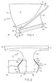
- FIG. 1 Illustrated in FIG. 1 is an exemplary gas turbine engine blade assembly 12 having a blade 10 illustrated as a fan blade.
- the blade 10 includes an airfoil 14 that extends radially outwardly from a blade platform 16 and axially from a blade leading edge 20 to a blade trailing edge 22.
- a blade shank 26 extends radially inwardly to a blade dovetail root 30 which is dovetail-shaped to be received by a dovetail-shaped disk slot in a gas turbine engine disk or rotor.
- a cross broach or root slot 32 having a radially inwardly facing slot surface 33, extends into a bottom 34 of the dovetail root 30 between radially inwardly extending leading and trailing edge tabs 36 and 38 at leading and trailing root edges 42 and 44.
- a resilient root shim 50 is disposed in the root slot 32 and around the dovetail root 30 to which it generally conforms.
- the shim 50 generally conforms to a cross-sectional dovetail shape 51 of the dovetail root 30 through the root slot 32.
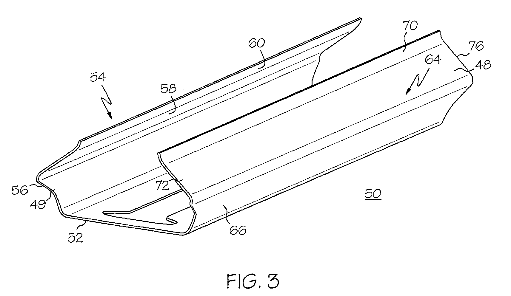
- the shim 50 has a longitudinally extending flat base 52 and transversely spaced apart first and second walls 54 and 64 that extend upwardly from the base 52.
- the first and second walls 54 and 64 have first and second lower portions 56 and 66 that extend at an angle away from the base 52 and from each other.
- the first and second walls 54 and 64 have a first and second upper portions 58 and 68 that extend towards each other and first and second end portions 60 and 70 that generally conforms to a transition portion 71 (illustrated in FIG. 2) of the blade between the blade shank 26 and the blade dovetail root 30.
- the shim 50 is made from thin resilient metal sheet and may have anti-friction or anti-fretting coatings on inner and/or outer sides 48 and 49 of the shim.
- the shim 50 extends from a forward end 72 to a aft end 76.
- the leading edge tab 36 is received within a forward slot 74 formed in the forward end 72 of the base 52.
- the trailing edge tab 38 is received within an aft slot 78 formed in the aft end 76 of the base 52.
- the cutbacks 80 include vertical cutback edges 82 extending upwardly from the base 52 through a portion, illustrated as about 1/2, of the first and second lower portions 56 and 66 of the first and second walls 54 and 64, respectively.
- Longitudinal cutback edges 84 extend substantially longitudinally and downwardly towards the vertical cutback edges 82.
- Fillets 86 are disposed between the longitudinal cutback edges 84 and the vertical cutback edges 82. This provides a smooth transition for the cutbacks 80 between the horizontal base 52 and vertical cutback edges of the first and second lower portions 56 and 66 of the first and second walls 54 and 64, respectively.
- the shim 50 has a dovetail shim portion 87 with a shim dovetail height 88 that is smaller than a blade root height 89 of the dovetail root 30 of the blade 10 to accommodate the root slot 32 and conform to the dovetail shape of the dovetail root.
- the dovetail shim portion 87 with the dovetail shape 51 substantially conforms to at least a portion of the cross-sectional dovetail shape 51 of the dovetail root 30 through the root slot 32.
- the base 52 is disposed within the root slot 32.
- the shim 50 must be flexible enough to be spread apart so that it can fit over the larger dovetail blade root 30 yet not break or deform so as to lose its resiliency and its ability to conform and maintain its snap fit on the blade root.
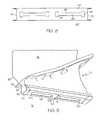
- Two longitudinally extending elongated base apertures 90 in the base 52 provide flexibility to the base and shim 50. More than two elongated base apertures 90 may be used.
- Each of the base apertures 90 has a main region 92 and longitudinally spaced apart rounded end regions 94 as illustrated in FIGS. 4, 7, 8, and 9. Aperture sides 98 of the main region 92 are substantially parallel and straight. Illustrated in FIGS. 4, 7, 8 are two dog-bone-shaped base apertures 95 in which the rounded end regions 94 are wider than the main region 92.
- FIG. 9 illustrates two rounded end base apertures 99 with semi-circular rounded end regions 102 having a width W which is the same
Landscapes
- Engineering & Computer Science (AREA)
- Mechanical Engineering (AREA)
- General Engineering & Computer Science (AREA)
- Turbine Rotor Nozzle Sealing (AREA)
Abstract
Description
Claims (11)
- A gas turbine engine blade root shim (50) comprising:a dovetail shim portion (87) with a dovetail shape (51),the dovetail shim portion (87) including a longitudinally extending substantially flat base (52) and distal first and second longitudinally spaced apart forward and aft ends (72 and 76),transversely spaced apart first and second walls (54 and 64) extend upwardly from the base (52),at least two longitudinally extending elongated base apertures (90) in the base (52), andeach of the base apertures (90) include a main region (92) and longitudinally spaced apart rounded end regions (94).
- A blade root shim (50) as claimed in claim 1, further comprising the main region (92) of the base apertures (90) having substantially parallel and straight aperture sides (98).
- A blade root shim (50) as claimed in claim 2, wherein the base apertures (90) are dog-bone-shaped base apertures (95) and the rounded end regions (94) are wider than the main region (92).
- A blade root shim (50) as claimed in claim 2, wherein the base apertures (90) are rounded end base apertures (99) and the rounded end regions (94) are semi-circular rounded end regions (102) having a width (W) which is the same width as that of the main region (92).
- A blade root shim (50) as claimed in claim 1, further comprising:the first and second walls (54 and 64) having first and second lower portions (56 and 66) extending upwardly from and at an angle away from the base (52) and from each other, andfirst and second upper portions (58 and 68) extending upwardly from the first and second lower portions (56 and 66) respectively and towards each other.
- A blade root shim (50) as claimed in claim 5, further comprising the main region (92) of the base apertures (90) having substantially parallel and straight aperture sides (98).
- A blade root shim (50) as claimed in claim 6, wherein the base apertures (90) are dog-bone-shaped base apertures (95) and the rounded end regions (94) are wider than the main region (92).
- A blade root shim (50) as claimed in claim 6, wherein the base apertures (90) are rounded end base apertures (99) and the rounded end regions (94) are semi-circular rounded end regions (102) having a width (W) which is the same width as that of the main region (92).
- A blade root shim (50) as claimed in claim 5, further comprising forward and aft slots (74 and 78) in the base (52) at the forward and aft ends (72 and 76) of the dovetail shim portion (87).
- A blade root shim (50) as claimed in claim 9, further comprising cutbacks (80) in the first and second lower portions (56 and 66) of the first and second walls (54 and 64) respectively extending from the base (52) at the forward and aft slots (74 and 78) to forward and aft vertical shim edges (104 and 106) of the first and second lower portions (56 and 66).
- A blade root shim (50) as claimed in claim 10, further comprising:vertical cutback edges (82) of the cutbacks (80) extending upwardly from the base (52) through a portion of the first and second lower portions (56 and 66) of the first and second walls (54 and 64) respectively,longitudinal cutback edges (84) of the cutbacks (80) extending substantially longitudinally and downwardly towards the vertical cutback edges (82), andfillets (86) disposed between the longitudinal cutback edges (84) and the vertical cutback edges (82).
Applications Claiming Priority (2)
| Application Number | Priority Date | Filing Date | Title |
|---|---|---|---|
| US356238 | 1989-05-24 | ||
| US10/356,238 US6860722B2 (en) | 2003-01-31 | 2003-01-31 | Snap on blade shim |
Publications (3)
| Publication Number | Publication Date |
|---|---|
| EP1443180A2 true EP1443180A2 (en) | 2004-08-04 |
| EP1443180A3 EP1443180A3 (en) | 2006-06-28 |
| EP1443180B1 EP1443180B1 (en) | 2008-10-01 |
Family
ID=32655603
Family Applications (1)
| Application Number | Title | Priority Date | Filing Date |
|---|---|---|---|
| EP04250460A Expired - Lifetime EP1443180B1 (en) | 2003-01-31 | 2004-01-28 | Snap-on turbine blade shim |
Country Status (5)
| Country | Link |
|---|---|
| US (1) | US6860722B2 (en) |
| EP (1) | EP1443180B1 (en) |
| JP (1) | JP4512377B2 (en) |
| CN (1) | CN100406682C (en) |
| DE (1) | DE602004016783D1 (en) |
Cited By (2)
| Publication number | Priority date | Publication date | Assignee | Title |
|---|---|---|---|---|
| EP2719864A1 (en) * | 2012-10-12 | 2014-04-16 | MTU Aero Engines GmbH | Adapter for a blade-disc connection for a rotor of a fluid flow engine and a corresponding rotor of a fluid flow engine |
| WO2015108616A1 (en) * | 2014-01-16 | 2015-07-23 | General Electric Company | Composite blade root stress reducing shim |
Families Citing this family (29)
| Publication number | Priority date | Publication date | Assignee | Title |
|---|---|---|---|---|
| EP1557534A1 (en) * | 2004-01-20 | 2005-07-27 | Siemens Aktiengesellschaft | Turbine blade and gas turbine with such a turbine blade |
| FR2890684B1 (en) * | 2005-09-15 | 2007-12-07 | Snecma | CLINKING FOR TURBOREACTOR BLADE |
| US7588418B2 (en) * | 2006-09-19 | 2009-09-15 | General Electric Company | Methods and apparatus for assembling turbine engines |
| US7806655B2 (en) * | 2007-02-27 | 2010-10-05 | General Electric Company | Method and apparatus for assembling blade shims |
| FR2913735B1 (en) * | 2007-03-16 | 2013-04-19 | Snecma | ROTOR DISC OF A TURBOMACHINE |
| FR2918703B1 (en) * | 2007-07-13 | 2009-10-16 | Snecma Sa | ROTOR ASSEMBLY OF TURBOMACHINE |
| FR2918702B1 (en) * | 2007-07-13 | 2009-10-16 | Snecma Sa | CLINKING FOR TURBOMACHINE BLADE |
| FR2921409B1 (en) | 2007-09-25 | 2009-12-18 | Snecma | CLINKING FOR TURBOMACHINE DAWN. |
| US8210819B2 (en) * | 2008-02-22 | 2012-07-03 | Siemens Energy, Inc. | Airfoil structure shim |
| US8172506B2 (en) * | 2008-11-26 | 2012-05-08 | General Electric Company | Method and system for cooling engine components |
| FR2938872B1 (en) * | 2008-11-26 | 2015-11-27 | Snecma | ANTI-WEAR DEVICE FOR AUBES OF A TURBINE DISPENSER OF AERONAUTICAL TURBOMACHINE |
| FR2945074B1 (en) * | 2009-04-29 | 2011-06-03 | Snecma | REINFORCED BLOW OF BREATHING BLADE |
| FR2963383B1 (en) * | 2010-07-27 | 2016-09-09 | Snecma | DUST OF TURBOMACHINE, ROTOR, LOW PRESSURE TURBINE AND TURBOMACHINE EQUIPPED WITH SUCH A DAWN |
| FR2981132B1 (en) * | 2011-10-10 | 2013-12-06 | Snecma | DISCHARGE COOLING TURBOMACHINE ASSEMBLY |
| US20130134678A1 (en) * | 2011-11-29 | 2013-05-30 | General Electric Company | Shim seal assemblies and assembly methods for stationary components of rotary machines |
| US9840917B2 (en) | 2011-12-13 | 2017-12-12 | United Technologies Corporation | Stator vane shroud having an offset |
| US8920112B2 (en) | 2012-01-05 | 2014-12-30 | United Technologies Corporation | Stator vane spring damper |
| US8899914B2 (en) | 2012-01-05 | 2014-12-02 | United Technologies Corporation | Stator vane integrated attachment liner and spring damper |
| US9410439B2 (en) * | 2012-09-14 | 2016-08-09 | United Technologies Corporation | CMC blade attachment shim relief |
| US9500083B2 (en) * | 2012-11-26 | 2016-11-22 | U.S. Department Of Energy | Apparatus and method to reduce wear and friction between CMC-to-metal attachment and interface |
| WO2014143318A1 (en) | 2013-03-13 | 2014-09-18 | United Technologies Corporation | Blade wear pads and manufacture methods |
| US9745856B2 (en) | 2013-03-13 | 2017-08-29 | Rolls-Royce Corporation | Platform for ceramic matrix composite turbine blades |
| US10753368B2 (en) * | 2016-08-23 | 2020-08-25 | Raytheon Technologies Corporation | Multi-piece non-linear airfoil |
| US10767498B2 (en) | 2018-04-03 | 2020-09-08 | Rolls-Royce High Temperature Composites Inc. | Turbine disk with pinned platforms |
| US10890081B2 (en) | 2018-04-23 | 2021-01-12 | Rolls-Royce Corporation | Turbine disk with platforms coupled to disk |
| US10577961B2 (en) | 2018-04-23 | 2020-03-03 | Rolls-Royce High Temperature Composites Inc. | Turbine disk with blade supported platforms |
| CN113833691A (en) * | 2020-06-08 | 2021-12-24 | 中国航发商用航空发动机有限责任公司 | Fan assembly and turbofan engine |
| FR3113421B1 (en) * | 2020-08-11 | 2022-11-04 | Safran Aircraft Engines | FLASH FOR ROTOR BLADE |
| KR20230091604A (en) | 2021-12-16 | 2023-06-23 | 한화에어로스페이스 주식회사 | Rotor assembly with protection shim and gas turbine engine including the same |
Family Cites Families (8)
| Publication number | Priority date | Publication date | Assignee | Title |
|---|---|---|---|---|
| US5160243A (en) | 1991-01-15 | 1992-11-03 | General Electric Company | Turbine blade wear protection system with multilayer shim |
| US5240375A (en) | 1992-01-10 | 1993-08-31 | General Electric Company | Wear protection system for turbine engine rotor and blade |
| JPH0813443B2 (en) * | 1992-11-11 | 1996-02-14 | ダイアトップ株式会社 | Chainsaw guide plate |
| JPH07247804A (en) * | 1993-01-07 | 1995-09-26 | General Electric Co <Ge> | Rotor and blade assemblies for gas turbine engines, and multilayer coated shims |
| JPH09310603A (en) * | 1996-05-21 | 1997-12-02 | Hitachi Ltd | gas turbine |
| US6202273B1 (en) * | 1999-07-30 | 2001-03-20 | General Electric Company | Shim removing tool |
| US6290466B1 (en) | 1999-09-17 | 2001-09-18 | General Electric Company | Composite blade root attachment |
| US6431835B1 (en) | 2000-10-17 | 2002-08-13 | Honeywell International, Inc. | Fan blade compliant shim |
-
2003
- 2003-01-31 US US10/356,238 patent/US6860722B2/en not_active Expired - Lifetime
-
2004
- 2004-01-28 EP EP04250460A patent/EP1443180B1/en not_active Expired - Lifetime
- 2004-01-28 DE DE602004016783T patent/DE602004016783D1/en not_active Expired - Lifetime
- 2004-01-30 JP JP2004022384A patent/JP4512377B2/en not_active Expired - Fee Related
- 2004-02-02 CN CNB2004100035153A patent/CN100406682C/en not_active Expired - Lifetime
Cited By (3)
| Publication number | Priority date | Publication date | Assignee | Title |
|---|---|---|---|---|
| EP2719864A1 (en) * | 2012-10-12 | 2014-04-16 | MTU Aero Engines GmbH | Adapter for a blade-disc connection for a rotor of a fluid flow engine and a corresponding rotor of a fluid flow engine |
| WO2015108616A1 (en) * | 2014-01-16 | 2015-07-23 | General Electric Company | Composite blade root stress reducing shim |
| US10837457B2 (en) | 2014-01-16 | 2020-11-17 | General Electric Company | Composite blade root stress reducing shim |
Also Published As
| Publication number | Publication date |
|---|---|
| JP2004232642A (en) | 2004-08-19 |
| EP1443180A3 (en) | 2006-06-28 |
| EP1443180B1 (en) | 2008-10-01 |
| CN100406682C (en) | 2008-07-30 |
| CN1519459A (en) | 2004-08-11 |
| JP4512377B2 (en) | 2010-07-28 |
| DE602004016783D1 (en) | 2008-11-13 |
| US20040151590A1 (en) | 2004-08-05 |
| US6860722B2 (en) | 2005-03-01 |
Similar Documents
| Publication | Publication Date | Title |
|---|---|---|
| EP1443180B1 (en) | Snap-on turbine blade shim | |
| US8038404B2 (en) | Steam turbine and rotating blade | |
| EP1813771B1 (en) | Bladed rotor assembly | |
| EP1522677A2 (en) | Blade damper | |
| EP0478234A1 (en) | Stress-relieved rotor blade attachment slot | |
| US6431835B1 (en) | Fan blade compliant shim | |
| EP0431766B1 (en) | Improved attachment of a gas turbine engine blade to a turbine rotor disc | |
| JP5579965B2 (en) | Apparatus for manufacturing a rotor assembly | |
| EP2149674B1 (en) | Bladed turbine rotor with vibration damper | |
| US7097428B2 (en) | Integral cover bucket design | |
| EP1118747A3 (en) | An aerofoil for an axial flow turbomachine | |
| JP4869616B2 (en) | Steam turbine blade, steam turbine rotor, steam turbine using the same, and power plant | |
| EP2423442B1 (en) | Electroformed conforming rubstrip | |
| EP2177716B1 (en) | Turbine blade with mistake proof feature and corresponding assembly | |
| EP2952685B1 (en) | Airfoil for a gas turbine engine, a gas turbine engine and a method for reducing frictional heating between airfoils and a case of a gas turbine engine | |
| US10941671B2 (en) | Gas turbine engine component incorporating a seal slot | |
| CA2566529A1 (en) | Blade fixing relief mismatch | |
| EP1939401A2 (en) | Methods and apparatus for load transfer in rotor assemblies | |
| US8047797B2 (en) | Steam turbine and rotating blade | |
| EP2669477B1 (en) | Shroud for airfoils | |
| JP2011021602A (en) | Coating for turbo machine | |
| JPS61129403A (en) | Coupling device of turbine moving blade |
Legal Events
| Date | Code | Title | Description |
|---|---|---|---|
| PUAI | Public reference made under article 153(3) epc to a published international application that has entered the european phase |
Free format text: ORIGINAL CODE: 0009012 |
|
| AK | Designated contracting states |
Kind code of ref document: A2 Designated state(s): AT BE BG CH CY CZ DE DK EE ES FI FR GB GR HU IE IT LI LU MC NL PT RO SE SI SK TR |
|
| AX | Request for extension of the european patent |
Extension state: AL LT LV MK |
|
| PUAL | Search report despatched |
Free format text: ORIGINAL CODE: 0009013 |
|
| AK | Designated contracting states |
Kind code of ref document: A3 Designated state(s): AT BE BG CH CY CZ DE DK EE ES FI FR GB GR HU IE IT LI LU MC NL PT RO SE SI SK TR |
|
| AX | Request for extension of the european patent |
Extension state: AL LT LV MK |
|
| 17P | Request for examination filed |
Effective date: 20061228 |
|
| AKX | Designation fees paid |
Designated state(s): BE DE FR GB |
|
| GRAP | Despatch of communication of intention to grant a patent |
Free format text: ORIGINAL CODE: EPIDOSNIGR1 |
|
| RTI1 | Title (correction) |
Free format text: SNAP-ON TURBINE BLADE SHIM |
|
| GRAS | Grant fee paid |
Free format text: ORIGINAL CODE: EPIDOSNIGR3 |
|
| GRAA | (expected) grant |
Free format text: ORIGINAL CODE: 0009210 |
|
| AK | Designated contracting states |
Kind code of ref document: B1 Designated state(s): BE DE FR GB |
|
| REG | Reference to a national code |
Ref country code: GB Ref legal event code: FG4D |
|
| REF | Corresponds to: |
Ref document number: 602004016783 Country of ref document: DE Date of ref document: 20081113 Kind code of ref document: P |
|
| PLBE | No opposition filed within time limit |
Free format text: ORIGINAL CODE: 0009261 |
|
| STAA | Information on the status of an ep patent application or granted ep patent |
Free format text: STATUS: NO OPPOSITION FILED WITHIN TIME LIMIT |
|
| 26N | No opposition filed |
Effective date: 20090702 |
|
| REG | Reference to a national code |
Ref country code: FR Ref legal event code: PLFP Year of fee payment: 13 |
|
| REG | Reference to a national code |
Ref country code: FR Ref legal event code: PLFP Year of fee payment: 14 |
|
| PGFP | Annual fee paid to national office [announced via postgrant information from national office to epo] |
Ref country code: DE Payment date: 20170125 Year of fee payment: 14 Ref country code: FR Payment date: 20170125 Year of fee payment: 14 |
|
| PGFP | Annual fee paid to national office [announced via postgrant information from national office to epo] |
Ref country code: BE Payment date: 20170127 Year of fee payment: 14 Ref country code: GB Payment date: 20170127 Year of fee payment: 14 |
|
| REG | Reference to a national code |
Ref country code: DE Ref legal event code: R119 Ref document number: 602004016783 Country of ref document: DE |
|
| GBPC | Gb: european patent ceased through non-payment of renewal fee |
Effective date: 20180128 |
|
| PG25 | Lapsed in a contracting state [announced via postgrant information from national office to epo] |
Ref country code: FR Free format text: LAPSE BECAUSE OF NON-PAYMENT OF DUE FEES Effective date: 20180131 Ref country code: DE Free format text: LAPSE BECAUSE OF NON-PAYMENT OF DUE FEES Effective date: 20180801 |
|
| REG | Reference to a national code |
Ref country code: FR Ref legal event code: ST Effective date: 20180928 |
|
| REG | Reference to a national code |
Ref country code: BE Ref legal event code: MM Effective date: 20180131 |
|
| PG25 | Lapsed in a contracting state [announced via postgrant information from national office to epo] |
Ref country code: GB Free format text: LAPSE BECAUSE OF NON-PAYMENT OF DUE FEES Effective date: 20180128 Ref country code: BE Free format text: LAPSE BECAUSE OF NON-PAYMENT OF DUE FEES Effective date: 20180131 |