EP1522677A2 - Blade damper - Google Patents
Blade damper Download PDFInfo
- Publication number
- EP1522677A2 EP1522677A2 EP04256127A EP04256127A EP1522677A2 EP 1522677 A2 EP1522677 A2 EP 1522677A2 EP 04256127 A EP04256127 A EP 04256127A EP 04256127 A EP04256127 A EP 04256127A EP 1522677 A2 EP1522677 A2 EP 1522677A2
- Authority
- EP
- European Patent Office
- Prior art keywords
- seal
- damper
- damping
- blades
- damper member
- Prior art date
- Legal status (The legal status is an assumption and is not a legal conclusion. Google has not performed a legal analysis and makes no representation as to the accuracy of the status listed.)
- Granted
Links
Images


Classifications
-
- F—MECHANICAL ENGINEERING; LIGHTING; HEATING; WEAPONS; BLASTING
- F01—MACHINES OR ENGINES IN GENERAL; ENGINE PLANTS IN GENERAL; STEAM ENGINES
- F01D—NON-POSITIVE DISPLACEMENT MACHINES OR ENGINES, e.g. STEAM TURBINES
- F01D11/00—Preventing or minimising internal leakage of working-fluid, e.g. between stages
- F01D11/005—Sealing means between non relatively rotating elements
- F01D11/006—Sealing the gap between rotor blades or blades and rotor
- F01D11/008—Sealing the gap between rotor blades or blades and rotor by spacer elements between the blades, e.g. independent interblade platforms
-
- F—MECHANICAL ENGINEERING; LIGHTING; HEATING; WEAPONS; BLASTING
- F01—MACHINES OR ENGINES IN GENERAL; ENGINE PLANTS IN GENERAL; STEAM ENGINES
- F01D—NON-POSITIVE DISPLACEMENT MACHINES OR ENGINES, e.g. STEAM TURBINES
- F01D5/00—Blades; Blade-carrying members; Heating, heat-insulating, cooling or antivibration means on the blades or the members
- F01D5/12—Blades
- F01D5/22—Blade-to-blade connections, e.g. for damping vibrations
-
- F—MECHANICAL ENGINEERING; LIGHTING; HEATING; WEAPONS; BLASTING
- F05—INDEXING SCHEMES RELATING TO ENGINES OR PUMPS IN VARIOUS SUBCLASSES OF CLASSES F01-F04
- F05D—INDEXING SCHEME FOR ASPECTS RELATING TO NON-POSITIVE-DISPLACEMENT MACHINES OR ENGINES, GAS-TURBINES OR JET-PROPULSION PLANTS
- F05D2230/00—Manufacture
- F05D2230/60—Assembly methods
-
- F—MECHANICAL ENGINEERING; LIGHTING; HEATING; WEAPONS; BLASTING
- F05—INDEXING SCHEMES RELATING TO ENGINES OR PUMPS IN VARIOUS SUBCLASSES OF CLASSES F01-F04
- F05D—INDEXING SCHEME FOR ASPECTS RELATING TO NON-POSITIVE-DISPLACEMENT MACHINES OR ENGINES, GAS-TURBINES OR JET-PROPULSION PLANTS
- F05D2260/00—Function
- F05D2260/30—Retaining components in desired mutual position
-
- Y—GENERAL TAGGING OF NEW TECHNOLOGICAL DEVELOPMENTS; GENERAL TAGGING OF CROSS-SECTIONAL TECHNOLOGIES SPANNING OVER SEVERAL SECTIONS OF THE IPC; TECHNICAL SUBJECTS COVERED BY FORMER USPC CROSS-REFERENCE ART COLLECTIONS [XRACs] AND DIGESTS
- Y10—TECHNICAL SUBJECTS COVERED BY FORMER USPC
- Y10S—TECHNICAL SUBJECTS COVERED BY FORMER USPC CROSS-REFERENCE ART COLLECTIONS [XRACs] AND DIGESTS
- Y10S416/00—Fluid reaction surfaces, i.e. impellers
- Y10S416/50—Vibration damping features
Definitions
- the invention relates to turbomachinery. More particularly, the invention relates to dampers for damping relative motion of adjacent blades in a turbomachine rotor.
- a typical gas turbine engine has, in its compressor and turbine sections, a number of blade-carrying disks that rotate about the engine axis and are interspersed with arrays of vanes that do not.
- the periphery of each disk may have a circumferential array of convoluted blade retention slots which receive complementary root portions of associated blades.
- Neck portions of the blades extend outward to platform sections which have outboard surfaces that help to locally define an inboard surface of the core flowpath through the engine.
- the blade airfoil extends from a root at the platform outboard surface to an outboard tip. Thermal and mechanical stresses and wear can produce relative motion of adjacent blades. It is accordingly known to provide dampers between the platforms of adjacent blades.
- An exemplary damper is shown in U.S. Patent 4,872,812. Substantial ongoing efforts exist in improving blade damper technology.
- one aspect of the invention involves a turbomachine blade damper.
- a damper member has first and second damping surfaces for respectively engaging first and second surfaces of adjacent first and second blades.
- a seal has a first portion engaged to the damper member to provide location of the seal in at least one direction and a second portion for restricting gas flow by at least one of the blades.
- the seal may consist essentially of sheet metal and the damper member may consist essentially of cast or machined metal. Each may consist essentially of a nickel- or cobalt-based superalloy.
- the seal may be retained by the damper member against axial movement in at least one direction and against inward radial movement.
- One of the damping surfaces may have a radiused transverse section.
- the other damping surface may be relatively flat.
- the seal second portion may be at least partially wider than the damper member. That second portion may have a radial span of at least 2.0 mm and a circumferential span of at least 4.0 mm. The circumferential span may be effective so that first and second side portions of the second portion are accommodated within pockets of adjacent blades.
- the second portion may be, in major part, radially inboard of the damping member.
- the damper member may have a depending T-shaped projection.
- the seal may have a closed aperture accommodating a leg of the projection with an adjacent portion of the seal being captured by an underside of a head of the projection. The adjacent portion may be freed by a relative rotation about an axis of the leg to an orientation wherein the projection head may be extracted through the aperture.
- the damper member and seal may be brought together in a first orientation so that the projection passes into the aperture. The damper member and seal are then relatively rotated to a second orientation wherein the projection captures an adjacent portion of the retainer.
- First and second blades each have a root, an airfoil outboard of the root, and a platform and neck between the root.
- the combined platform and neck has first and second sides, the first side of one of the blades facing the second side of the other.
- Means are mounted in at least one pocket of at least one of the facing first and second sides for damping relative motion of the first and second blades and sealing against combustion gas upstream infiltration.
- the means may include a one piece seal member and a one piece damper member that further provides a degree retention for the seal member.
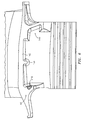
- FIG. 1 shows a blade 20 having an airfoil 22 with concave pressure and convex suction side surfaces 24 and 26 extending from an airfoil root 28 to an airfoil tip 30 and between leading and trailing edges 32 and 34.
- the airfoil root is formed at an outboard surface 36 of a platform 38 having first and second sides 40 and 42.
- the platform is outboard of a convoluted root 44 and separated therefrom by a neck 46.
- a wedge damper/seal assembly 50 is partially accommodated within a compartment in the platform and neck combination.
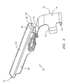
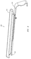
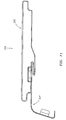
- FIG. 2 shows further features of the exemplary damper/seal assembly 50.
- a main body portion of a damper member 52 extends from an upstream end 54 to a downstream end 56 and has first and second damping surfaces 58 and 60.
- An underhung mass 62 depends inboard from the main portion of the damper member.
- a seal member 70 has an outboard shelf portion 72 for engaging the damper member.
- a depending portion 74 depends generally inboard from the shelf 72 and terminates in a bent under tab 76.
- a tri-bent tab 78 extends from a second side of the depending portion 74 and is bent partially upstream.
- the damper member and seal member are each formed as a unitary metal piece.
- Exemplary damper members may be cast or machined and exemplary seal members may be stamped and bent from sheet stock.
- Exemplary materials for each are nickel- or cobalt-based superalloys.
- preferred damper material is an equiax nickel-based superalloy such as Inconel Alloy 100, Special Metals Corporation, Huntington, West Virginia and preferred seal member material is a cobalt-based superalloy such as Haynes 188, Haynes International, Inc., Kokomo, Indiana.
- Exemplary seal member thickness is 0.20 mm-1.5 mm, more narrowly, 0.25 mm-0.80 mm. Both seal and damper member materials advantageously have high temperature reliability, at least in excess of 650°C and, preferably, near or in excess of 1100°C.
- the damper member and seal member may have interengageable features with mating surfaces for permitting the seal member to be retained by the damper member.
- cooperating surfaces include an upstream outboard surface portion of the shelf 72 and a downstream inboard surface portion of the underhung mass.
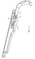
- FIG. 3 further shows that portion of the shelf as having a slot-like aperture 80 elongate in the longitudinal direction and accommodating the leg 82 of a T-shaped projection depending from the underhung mass underside and having a transversely-extending head 84 whose outboard-facing underside captures portions of the shelf along sides of the aperture to prevent the relative inboard movement of the seal member relative to the damper member.
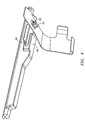
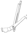
- the damper and seal assembly 50 may be assembled by initially translating the two together in an orientation transverse to their assembled orientation so that the projection head 84 (FIG. 4) is aligned with and passes through the aperture 80. The seal is then rotated in the first direction about the leg 82 to bring to the shelf upstream portion into a channel 90 outboard of the tongue 86 until the tab 88 contacts the adj acent side of the damper member.
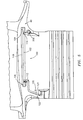
- FIG. 5 shows further details of the first side pocket 100 for accommodating the damper/seal assembly.
- the pocket has a first portion 102 essentially in the platform and extending from an upstream end 104 to downstream end 106 and having a bearing surface 108 for engaging the damper member main body second surface 60.
- the surface 108 extends continuously along an outboard extremity of the pocket first portion 102. Adjacent the ends 104 and 106, the pocket is also bounded by inboard surface portions 110 and 112 which help capture upstream and downstream end portions of the damper member main body against relative inboard movement beyond a given range.
- a pocket second portion 120 is formed essentially in an aft downstream buttress 122 of the neck and has an upstream-facing surface 124.
- the second portion 120 accommodates a second-side portion of the seal depending portion including the associated tab 78. The interaction between pocket portion 120 and tab 78 helps to locate the seal circumferentially between adjacent blade pockets.
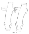
- FIG. 6 shows the second side 42 of the blade which may be in close facing spaced-apart relation to the first side 40 of the adjacent blade.
- a pocket 140 is formed in the aft buttress for receiving the first side portion of the seal member depending portion.
- the platform includes a surface 142 positioned to engage the first side of the damper member main body portion.
- the surface 142 extends longitudinally for substantially the length of the damper member and has a portion along a central depending projection 144.
- the projection 144 provides additional blade-to-damper contact area and damper anti-rotation when brought into contact with the first damping surface 58.
- FIG. 7 shows the surfaces 58 and 60 respectively engaging the surfaces 142 and 108 of adjacent blades in an installed condition.
- the surface 58 is positioned essentially radially relative to the engine axis and is essentially flat, as is the mating surface 142.
- the surface 60 may be less flat, namely slightly convex in transverse section such as having a radius of curvature of one or more values in an exemplary range of approximately 5-30 mm, more particularly 10-25 mm and, most particularly 12-20 mm.
- the transition 150 between the surfaces 58 and 60 and a transition 152 between the surface 60 and more radial inboard portion 154 of the adjacent side of the damper member may be more sharply radiused.
- the former may be radius at 0.2-1.0 mm and the latter at 0.7-1.5 mm
- FIG. 8 shows the action of the damper in accommodating movement of the blades between an at-rest position (broken lines) and a running position (solid lines). Wedging engagement is maintain by centrifugal action acting upon the wedge damper to wedge itself between the mating surfaces.
- An exemplary angle ⁇ between the surface 60 and a characteristic (e.g. mean, median, or central tangent) portion of the surface 58 is between 20°-80°.
- the illustrated damper main body serves as a "full-length" damper, meaning its associated contact surfaces extend nearly the entire length of the platforms subject to manufacturing constraints. For example, this may be approximately 60-80%.
- FIGS. 9 and 10 show an alternate damper/seal assembly 200 having a damper member 202 and a seal member 204.
- the seal member 204 extends farther upstream than the in first embodiment and has a protruding upstream portion 206 which may be captured within forward pockets 208 (FIG. 5) and 210 (FIG. 6) of the second and first sides of the associated blade platforms/necks.
- a similar T-shaped projection and slot arrangement is provided to couple the two pieces.
- the increased length of the seal member 204 provides additional protection against infiltration of hot upstream gases over the length of the platform.
- FIGS. 11 and 12 show a third damper/seal assembly 220 having a damper member 222 and a seal member 224.
- a pair of projections 226 and 228 extending outboard from opposite sides of the shelf (shown partially assembled in FIG. 12) become accommodated within compartments 229 on either side of the seal and straddle a web 230 between the compartments.
- An upstream portion of the shelf ahead of the projections may be captured between a tongue 240 and the rest of the damper member.
- the upstream portion of the shelf may be inserted within the channel at a slight angle and then the seal may be rotated outward with further insertion bringing the projections into the associated recesses.
Landscapes
- Engineering & Computer Science (AREA)
- Mechanical Engineering (AREA)
- General Engineering & Computer Science (AREA)
- Turbine Rotor Nozzle Sealing (AREA)
- Structures Of Non-Positive Displacement Pumps (AREA)
Abstract
Description
- The invention relates to turbomachinery. More particularly, the invention relates to dampers for damping relative motion of adjacent blades in a turbomachine rotor.
- A typical gas turbine engine has, in its compressor and turbine sections, a number of blade-carrying disks that rotate about the engine axis and are interspersed with arrays of vanes that do not. The periphery of each disk may have a circumferential array of convoluted blade retention slots which receive complementary root portions of associated blades. Neck portions of the blades extend outward to platform sections which have outboard surfaces that help to locally define an inboard surface of the core flowpath through the engine. The blade airfoil extends from a root at the platform outboard surface to an outboard tip. Thermal and mechanical stresses and wear can produce relative motion of adjacent blades. It is accordingly known to provide dampers between the platforms of adjacent blades. An exemplary damper is shown in U.S. Patent 4,872,812. Substantial ongoing efforts exist in improving blade damper technology.
- Accordingly, one aspect of the invention involves a turbomachine blade damper. A damper member has first and second damping surfaces for respectively engaging first and second surfaces of adjacent first and second blades. A seal has a first portion engaged to the damper member to provide location of the seal in at least one direction and a second portion for restricting gas flow by at least one of the blades.
- In various implementations, the seal may consist essentially of sheet metal and the damper member may consist essentially of cast or machined metal. Each may consist essentially of a nickel- or cobalt-based superalloy. The seal may be retained by the damper member against axial movement in at least one direction and against inward radial movement. One of the damping surfaces may have a radiused transverse section. The other damping surface may be relatively flat. The seal second portion may be at least partially wider than the damper member. That second portion may have a radial span of at least 2.0 mm and a circumferential span of at least 4.0 mm. The circumferential span may be effective so that first and second side portions of the second portion are accommodated within pockets of adjacent blades. The second portion may be, in major part, radially inboard of the damping member. The damper member may have a depending T-shaped projection. The seal may have a closed aperture accommodating a leg of the projection with an adjacent portion of the seal being captured by an underside of a head of the projection. The adjacent portion may be freed by a relative rotation about an axis of the leg to an orientation wherein the projection head may be extracted through the aperture. In a method of assembly, the damper member and seal may be brought together in a first orientation so that the projection passes into the aperture. The damper member and seal are then relatively rotated to a second orientation wherein the projection captures an adjacent portion of the retainer.
- Another aspect of the invention involves a turbomachine blade combination. First and second blades each have a root, an airfoil outboard of the root, and a platform and neck between the root. The combined platform and neck has first and second sides, the first side of one of the blades facing the second side of the other. Means are mounted in at least one pocket of at least one of the facing first and second sides for damping relative motion of the first and second blades and sealing against combustion gas upstream infiltration.
- In various implementations, the means may include a one piece seal member and a one piece damper member that further provides a degree retention for the seal member.
- The details of one or more embodiments of the invention are set forth in the accompanying drawings and the description below. Other features and advantages of the invention will be apparent from the description and drawings, and from the claims.
-
- FIG. 1 is a view of a blade and damper assembly combination.
- FIG. 2 is a view of the damper assembly of the blade of FIG. 1.
- FIG. 3 is a second view of the damper assembly of FIG. 2.
- FIG. 4 is a third view of the damper assembly of FIG. 2 in a state of partial assembly /disassembly.
- FIG. 5 is a view of a blade pressure side platform and neck area having surfaces for engaging one side of the damper assembly of FIG. 2.
- FIG. 6 is a view of a blade suction side neck area having surfaces for engaging a second side of the damper assembly of FIG. 2.
- FIG. 7 is a sectional view of an adjacent pair of blades engaged to the damper assembly of FIG. 2.
- FIG. 8 is a schematic sectional view showing rest and running positions of the blade combination of FIG. 7.
- FIG. 9 is a view of a second damper assembly.
- FIG. 10 is a view of the damper assembly of FIG. 9 in an intermediate stage of assembly/disassembly.
- FIG. 11 is a view of a third damper assembly.
- FIG. 12 is a view of the third damper assembly of FIG. 11 in an intermediate stage of assembly/disassembly.
-
- Like reference numbers and designations in the various drawings indicate like elements.
- FIG. 1 shows a
blade 20 having anairfoil 22 with concave pressure and convexsuction side surfaces airfoil root 28 to anairfoil tip 30 and between leading andtrailing edges outboard surface 36 of aplatform 38 having first andsecond sides root 44 and separated therefrom by aneck 46. A wedge damper/seal assembly 50 is partially accommodated within a compartment in the platform and neck combination. - FIG. 2 shows further features of the exemplary damper/
seal assembly 50. A main body portion of adamper member 52 extends from anupstream end 54 to adownstream end 56 and has first andsecond damping surfaces underhung mass 62 depends inboard from the main portion of the damper member. Aseal member 70 has anoutboard shelf portion 72 for engaging the damper member. A dependingportion 74 depends generally inboard from theshelf 72 and terminates in a bent undertab 76. A tri-benttab 78 extends from a second side of the dependingportion 74 and is bent partially upstream. In the exemplary embodiment, the damper member and seal member are each formed as a unitary metal piece. Exemplary damper members may be cast or machined and exemplary seal members may be stamped and bent from sheet stock. Exemplary materials for each are nickel- or cobalt-based superalloys. In particular, preferred damper material is an equiax nickel-based superalloy such asInconel Alloy 100, Special Metals Corporation, Huntington, West Virginia and preferred seal member material is a cobalt-based superalloy such as Haynes 188, Haynes International, Inc., Kokomo, Indiana. Exemplary seal member thickness is 0.20 mm-1.5 mm, more narrowly, 0.25 mm-0.80 mm. Both seal and damper member materials advantageously have high temperature reliability, at least in excess of 650°C and, preferably, near or in excess of 1100°C. The damper member and seal member may have interengageable features with mating surfaces for permitting the seal member to be retained by the damper member. In the illustrated embodiment of FIG. 2, cooperating surfaces include an upstream outboard surface portion of theshelf 72 and a downstream inboard surface portion of the underhung mass. FIG. 3 further shows that portion of the shelf as having a slot-like aperture 80 elongate in the longitudinal direction and accommodating theleg 82 of a T-shaped projection depending from the underhung mass underside and having a transversely-extendinghead 84 whose outboard-facing underside captures portions of the shelf along sides of the aperture to prevent the relative inboard movement of the seal member relative to the damper member. FIG. 3 further shows a downstream protrudingtongue 86 of the underhung mass below a leading portion of theshelf 72 and whose outboard surface engages an underside of the upstream portion of the seal shelf to further prevent such translation. The shelf further includes an outboard-extendingtab 88 along its second side and having a surface contacting an adjacent second side surface of the underhung mass to resist relative rotation of the seal member in a first direction about an axis of theleg 82. With the foregoing in mind, the damper and sealassembly 50 may be assembled by initially translating the two together in an orientation transverse to their assembled orientation so that the projection head 84 (FIG. 4) is aligned with and passes through theaperture 80. The seal is then rotated in the first direction about theleg 82 to bring to the shelf upstream portion into achannel 90 outboard of thetongue 86 until thetab 88 contacts the adj acent side of the damper member. - FIG. 5 shows further details of the
first side pocket 100 for accommodating the damper/seal assembly. The pocket has afirst portion 102 essentially in the platform and extending from anupstream end 104 todownstream end 106 and having a bearingsurface 108 for engaging the damper member main bodysecond surface 60. Thesurface 108 extends continuously along an outboard extremity of the pocketfirst portion 102. Adjacent theends surface portions second portion 120 is formed essentially in an aft downstream buttress 122 of the neck and has an upstream-facingsurface 124. Thesecond portion 120 accommodates a second-side portion of the seal depending portion including the associatedtab 78. The interaction betweenpocket portion 120 andtab 78 helps to locate the seal circumferentially between adjacent blade pockets. - FIG. 6 shows the
second side 42 of the blade which may be in close facing spaced-apart relation to thefirst side 40 of the adjacent blade. Apocket 140 is formed in the aft buttress for receiving the first side portion of the seal member depending portion. The platform includes asurface 142 positioned to engage the first side of the damper member main body portion. Thesurface 142 extends longitudinally for substantially the length of the damper member and has a portion along a central dependingprojection 144. Theprojection 144 provides additional blade-to-damper contact area and damper anti-rotation when brought into contact with the first dampingsurface 58. With the blades assembled, the seal member depending portion and downstream section of the shelf portion span between the pockets of adjacent blades to help form a seal between the adjacent blades against upstream infiltration of hot gases. - FIG. 7 shows the
surfaces surfaces surface 58 is positioned essentially radially relative to the engine axis and is essentially flat, as is themating surface 142. Thesurface 60, however, may be less flat, namely slightly convex in transverse section such as having a radius of curvature of one or more values in an exemplary range of approximately 5-30 mm, more particularly 10-25 mm and, most particularly 12-20 mm. Thetransition 150 between thesurfaces transition 152 between thesurface 60 and more radialinboard portion 154 of the adjacent side of the damper member may be more sharply radiused. For example, the former may be radius at 0.2-1.0 mm and the latter at 0.7-1.5 mm - FIG. 8 shows the action of the damper in accommodating movement of the blades between an at-rest position (broken lines) and a running position (solid lines). Wedging engagement is maintain by centrifugal action acting upon the wedge damper to wedge itself between the mating surfaces. An exemplary angle between the
surface 60 and a characteristic (e.g. mean, median, or central tangent) portion of thesurface 58 is between 20°-80°. The illustrated damper main body serves as a "full-length" damper, meaning its associated contact surfaces extend nearly the entire length of the platforms subject to manufacturing constraints. For example, this may be approximately 60-80%. - FIGS. 9 and 10 show an alternate damper/
seal assembly 200 having adamper member 202 and aseal member 204. In the exemplary embodiment, theseal member 204 extends farther upstream than the in first embodiment and has a protrudingupstream portion 206 which may be captured within forward pockets 208 (FIG. 5) and 210 (FIG. 6) of the second and first sides of the associated blade platforms/necks. In the illustrated embodiment, a similar T-shaped projection and slot arrangement is provided to couple the two pieces. The increased length of theseal member 204 provides additional protection against infiltration of hot upstream gases over the length of the platform. - FIGS. 11 and 12 show a third damper/
seal assembly 220 having adamper member 222 and aseal member 224. A pair ofprojections compartments 229 on either side of the seal and straddle aweb 230 between the compartments. An upstream portion of the shelf ahead of the projections may be captured between atongue 240 and the rest of the damper member. To assemble the two components, the upstream portion of the shelf may be inserted within the channel at a slight angle and then the seal may be rotated outward with further insertion bringing the projections into the associated recesses. - One or more embodiments of the present invention have been described. Nevertheless, it will be understood that various modifications may be made without departing from the scope of the invention. For example, when applied as a reengineering of an existing turbine engine, details of the existing engine may influence details of any particular implementation. Accordingly, other embodiments are within the scope of the following claims.
Claims (12)
- A turbomachine blade damper comprising:a damper member (52;202;222) having first and second damping surfaces (58,60) for respectively engaging first and second surfaces of adjacent first and second blades (20); anda seal (70;204;224) having:a first portion (72) engaged to the damping member to resist movement of the seal in at least one direction; anda second portion (74) for restricting gas flow by at least one of the blades.
- The apparatus of claim wherein:the seal (70;204;224) consists essentially of sheet metal; andthe damper member (52;202;222) consists essentially of cast or machined metal.
- The apparatus of claim 2 wherein:the seal (70;204;224) consists essentially of a nickel- or cobalt-based superalloy; andthe damper member (52;202;222) consists essentially of a nickel- or cobalt-based superalloy.
- The apparatus of any preceding claim wherein:the damper member (52;202;222) retains the seal (70;204;224) against axial movement in at least one direction and against inward radial movement.
- The apparatus of any preceding claim wherein:one of said first and second damping surfaces (58,60) has a radiused transverse section; and the other of said first and second damping surfaces is flat relative to said one.
- The apparatus of any preceding claim wherein:the second portion of the seal (70;204;224) is at least partially wider than the damping member (52;202;222).
- The apparatus of any preceding claim wherein:the second portion (74) of the seal (70;204;224) has a radial span of at least 2.0mm and a circumferential span of at least 4.0mm.
- The apparatus of any preceding claim wherein:the second portion (74) of the seal (70;204;224) is, in major part, radially inboard of the damping member 52;202;222).
- The apparatus of any preceding claim wherein:the damper member (52;202) has a depending T-shaped projection; andthe seal (70;204) has a closed aperture accommodating a leg of the projection with an adjacent portion of the seal being captured by an underside of a head (84) of the projection and wherein the adjacent portion may be freed by a relative rotation about an axis of the leg to an orientation wherein the projection head may be extracted through the aperture.
- A method for assembling the turbomachine blade damper of any preceding claim comprising:bringing the damper member (52;202;222) and the seal (70;204;224) together in a first orientation so that a projection of the damping member passes into an aperture in the seal;relatively rotating the damper member and seal to a second orientation wherein the projection captures an adjacent portion of the retainer.
- A turbomachine blade combination comprising:first and second blades (20), each having:a root (44);an airfoil (22) outboard of the root; anda platform (38) and neck (46) between the root (44) and airfoil (22) and having first and second sides (40,42), the first side of one of the blades facing the second side of the other; andmeans (52;202;222) mounted in at least one pocket (100) of at least one of the facing first and second sides for damping relative motion of the first and second blades and sealing against combustion gas upstream infiltration.
- The combination of claim 11 wherein the means comprises:a one-piece seal (70;204;224); andone-piece damper member (52;202;222) that further provides a degree of retention for the seal member.
Priority Applications (1)
| Application Number | Priority Date | Filing Date | Title |
|---|---|---|---|
| EP11167184A EP2366872B1 (en) | 2003-10-08 | 2004-10-04 | Turbomachine blade damper assembly and method of assembling thereof |
Applications Claiming Priority (2)
| Application Number | Priority Date | Filing Date | Title |
|---|---|---|---|
| US681957 | 1984-12-14 | ||
| US10/681,957 US6932575B2 (en) | 2003-10-08 | 2003-10-08 | Blade damper |
Related Child Applications (1)
| Application Number | Title | Priority Date | Filing Date |
|---|---|---|---|
| EP11167184.8 Division-Into | 2011-05-23 |
Publications (3)
| Publication Number | Publication Date |
|---|---|
| EP1522677A2 true EP1522677A2 (en) | 2005-04-13 |
| EP1522677A3 EP1522677A3 (en) | 2008-09-03 |
| EP1522677B1 EP1522677B1 (en) | 2012-01-04 |
Family
ID=34314133
Family Applications (2)
| Application Number | Title | Priority Date | Filing Date |
|---|---|---|---|
| EP04256127A Expired - Fee Related EP1522677B1 (en) | 2003-10-08 | 2004-10-04 | Turbomachine blade damper assembly |
| EP11167184A Expired - Fee Related EP2366872B1 (en) | 2003-10-08 | 2004-10-04 | Turbomachine blade damper assembly and method of assembling thereof |
Family Applications After (1)
| Application Number | Title | Priority Date | Filing Date |
|---|---|---|---|
| EP11167184A Expired - Fee Related EP2366872B1 (en) | 2003-10-08 | 2004-10-04 | Turbomachine blade damper assembly and method of assembling thereof |
Country Status (5)
| Country | Link |
|---|---|
| US (1) | US6932575B2 (en) |
| EP (2) | EP1522677B1 (en) |
| JP (1) | JP2005113916A (en) |
| CA (1) | CA2483071A1 (en) |
| NO (1) | NO20044251L (en) |
Cited By (8)
| Publication number | Priority date | Publication date | Assignee | Title |
|---|---|---|---|---|
| EP1617044A1 (en) * | 2004-07-13 | 2006-01-18 | General Electric Company | Selectively thinned turbine blade |
| EP2053286A1 (en) * | 2007-10-25 | 2009-04-29 | Siemens Aktiengesellschaft | Seal strip and turbine blade assembly |
| WO2009053169A1 (en) * | 2007-10-25 | 2009-04-30 | Siemens Aktiengesellschaft | Turbine blade assembly and seal strip |
| EP2500524A1 (en) * | 2011-03-15 | 2012-09-19 | United Technologies Corporation | Gas turbine engine blade and corresponding assemblage |
| EP2500525A1 (en) * | 2011-03-15 | 2012-09-19 | United Technologies Corporation | Damper pin |
| EP2381067A3 (en) * | 2010-04-21 | 2014-06-18 | United Technologies Corporation | Turbine engine assembled seal |
| EP2836682A4 (en) * | 2012-01-31 | 2016-06-01 | United Technologies Corp | Turbine blade damper seal |
| US10851661B2 (en) | 2017-08-01 | 2020-12-01 | General Electric Company | Sealing system for a rotary machine and method of assembling same |
Families Citing this family (31)
| Publication number | Priority date | Publication date | Assignee | Title |
|---|---|---|---|---|
| US7090466B2 (en) * | 2004-09-14 | 2006-08-15 | General Electric Company | Methods and apparatus for assembling gas turbine engine rotor assemblies |
| US7322797B2 (en) * | 2005-12-08 | 2008-01-29 | General Electric Company | Damper cooled turbine blade |
| US7731482B2 (en) * | 2006-06-13 | 2010-06-08 | General Electric Company | Bucket vibration damper system |
| FR2915510B1 (en) * | 2007-04-27 | 2009-11-06 | Snecma Sa | SHOCK ABSORBER FOR TURBOMACHINE BLADES |
| FR2923557B1 (en) * | 2007-11-12 | 2010-01-22 | Snecma | BLOWER DRAWER ASSEMBLY AND ITS SHOCK ABSORBER, BLOWER DAMPER AND METHOD FOR CALIBRATING THE SHOCK ABSORBER |
| US8221083B2 (en) | 2008-04-15 | 2012-07-17 | United Technologies Corporation | Asymmetrical rotor blade fir-tree attachment |
| US8137072B2 (en) * | 2008-10-31 | 2012-03-20 | Solar Turbines Inc. | Turbine blade including a seal pocket |
| US8393869B2 (en) | 2008-12-19 | 2013-03-12 | Solar Turbines Inc. | Turbine blade assembly including a damper |
| JP5512977B2 (en) * | 2009-01-07 | 2014-06-04 | スネクマ | Fan blade assembly, damper assembly, fan blade damper and damper calibration method |
| FR2949142B1 (en) * | 2009-08-11 | 2011-10-14 | Snecma | VIBRATION SHOCK ABSORBER BLOCK FOR BLOWER DAWN |
| US9133855B2 (en) * | 2010-11-15 | 2015-09-15 | Mtu Aero Engines Gmbh | Rotor for a turbo machine |
| US8876478B2 (en) * | 2010-11-17 | 2014-11-04 | General Electric Company | Turbine blade combined damper and sealing pin and related method |
| FR2970033B1 (en) * | 2011-01-04 | 2015-10-16 | Turbomeca | METHOD FOR DAMPING GAS TURBINE BLADE AND VIBRATION DAMPER IMPLEMENTATION |
| EP2520768A1 (en) * | 2011-05-02 | 2012-11-07 | MTU Aero Engines AG | Sealing device for an integrated bladed rotor base body of a turbomachine |
| US10287897B2 (en) | 2011-09-08 | 2019-05-14 | General Electric Company | Turbine rotor blade assembly and method of assembling same |
| US9334751B2 (en) | 2012-04-03 | 2016-05-10 | United Technologies Corporation | Variable vane inner platform damping |
| US9175570B2 (en) * | 2012-04-24 | 2015-11-03 | United Technologies Corporation | Airfoil including member connected by articulated joint |
| CN109386310A (en) | 2012-06-30 | 2019-02-26 | 通用电气公司 | Turbine blade sealing structure |
| EP2971555B1 (en) * | 2013-03-13 | 2021-04-28 | Raytheon Technologies Corporation | Rotor assembly with damper seal between blades |
| EP3044420A2 (en) | 2013-09-11 | 2016-07-20 | General Electric Company | Ply architecture for integral platform and damper retaining features in cmc turbine blades |
| US9732620B2 (en) * | 2013-09-26 | 2017-08-15 | United Technologies Corporation | Snap in platform damper and seal assembly for a gas turbine engine |
| EP2881544A1 (en) | 2013-12-09 | 2015-06-10 | Siemens Aktiengesellschaft | Airfoil device for a gas turbine and corresponding arrangement |
| US9797270B2 (en) * | 2013-12-23 | 2017-10-24 | Rolls-Royce North American Technologies Inc. | Recessable damper for turbine |
| US9856737B2 (en) * | 2014-03-27 | 2018-01-02 | United Technologies Corporation | Blades and blade dampers for gas turbine engines |
| US9995162B2 (en) * | 2014-10-20 | 2018-06-12 | United Technologies Corporation | Seal and clip-on damper system and device |
| US9810075B2 (en) | 2015-03-20 | 2017-11-07 | United Technologies Corporation | Faceted turbine blade damper-seal |
| US9920637B2 (en) * | 2015-04-07 | 2018-03-20 | United Technologies Corporation | Gas turbine engine damping device |
| US9976427B2 (en) * | 2015-05-26 | 2018-05-22 | United Technologies Corporation | Installation fault tolerant damper |
| DE102015112144A1 (en) * | 2015-07-24 | 2017-02-09 | Rolls-Royce Deutschland Ltd & Co Kg | Rotor device of an aircraft engine with a damping device between blades |
| JP6521273B2 (en) * | 2015-08-21 | 2019-05-29 | 三菱重工コンプレッサ株式会社 | Steam turbine |
| JP7039355B2 (en) * | 2018-03-28 | 2022-03-22 | 三菱重工業株式会社 | Rotating machine |
Citations (2)
| Publication number | Priority date | Publication date | Assignee | Title |
|---|---|---|---|---|
| US4872812A (en) | 1987-08-05 | 1989-10-10 | General Electric Company | Turbine blade plateform sealing and vibration damping apparatus |
| US5228835A (en) | 1992-11-24 | 1993-07-20 | United Technologies Corporation | Gas turbine blade seal |
Family Cites Families (12)
| Publication number | Priority date | Publication date | Assignee | Title |
|---|---|---|---|---|
| US3887298A (en) * | 1974-05-30 | 1975-06-03 | United Aircraft Corp | Apparatus for sealing turbine blade damper cavities |
| US4455122A (en) * | 1981-12-14 | 1984-06-19 | United Technologies Corporation | Blade to blade vibration damper |
| JPH0295702A (en) | 1988-09-30 | 1990-04-06 | Hitachi Ltd | Moving blade damper device |
| US4872810A (en) * | 1988-12-14 | 1989-10-10 | United Technologies Corporation | Turbine rotor retention system |
| US5226784A (en) * | 1991-02-11 | 1993-07-13 | General Electric Company | Blade damper |
| US5302085A (en) * | 1992-02-03 | 1994-04-12 | General Electric Company | Turbine blade damper |
| US5478207A (en) * | 1994-09-19 | 1995-12-26 | General Electric Company | Stable blade vibration damper for gas turbine engine |
| FR2726323B1 (en) * | 1994-10-26 | 1996-12-13 | Snecma | ASSEMBLY OF A ROTARY DISC AND BLADES, ESPECIALLY USED IN A TURBOMACHINE |
| US5513955A (en) * | 1994-12-14 | 1996-05-07 | United Technologies Corporation | Turbine engine rotor blade platform seal |
| US5573375A (en) * | 1994-12-14 | 1996-11-12 | United Technologies Corporation | Turbine engine rotor blade platform sealing and vibration damping device |
| US5827047A (en) * | 1996-06-27 | 1998-10-27 | United Technologies Corporation | Turbine blade damper and seal |
| US6354803B1 (en) | 2000-06-30 | 2002-03-12 | General Electric Company | Blade damper and method for making same |
-
2003
- 2003-10-08 US US10/681,957 patent/US6932575B2/en not_active Expired - Lifetime
-
2004
- 2004-09-29 CA CA002483071A patent/CA2483071A1/en not_active Abandoned
- 2004-10-04 EP EP04256127A patent/EP1522677B1/en not_active Expired - Fee Related
- 2004-10-04 EP EP11167184A patent/EP2366872B1/en not_active Expired - Fee Related
- 2004-10-05 JP JP2004292107A patent/JP2005113916A/en not_active Ceased
- 2004-10-07 NO NO20044251A patent/NO20044251L/en not_active Application Discontinuation
Patent Citations (2)
| Publication number | Priority date | Publication date | Assignee | Title |
|---|---|---|---|---|
| US4872812A (en) | 1987-08-05 | 1989-10-10 | General Electric Company | Turbine blade plateform sealing and vibration damping apparatus |
| US5228835A (en) | 1992-11-24 | 1993-07-20 | United Technologies Corporation | Gas turbine blade seal |
Cited By (12)
| Publication number | Priority date | Publication date | Assignee | Title |
|---|---|---|---|---|
| EP1617044A1 (en) * | 2004-07-13 | 2006-01-18 | General Electric Company | Selectively thinned turbine blade |
| EP2053286A1 (en) * | 2007-10-25 | 2009-04-29 | Siemens Aktiengesellschaft | Seal strip and turbine blade assembly |
| WO2009053169A1 (en) * | 2007-10-25 | 2009-04-30 | Siemens Aktiengesellschaft | Turbine blade assembly and seal strip |
| RU2486349C2 (en) * | 2007-10-25 | 2013-06-27 | Сименс Акциенгезелльшафт | Sealing ridge, assembly of turbine blades, and gas turbine containing such blade assembly |
| US8613599B2 (en) | 2007-10-25 | 2013-12-24 | Siemens Aktiengesellschaft | Turbine blade assembly and seal strip |
| EP2381067A3 (en) * | 2010-04-21 | 2014-06-18 | United Technologies Corporation | Turbine engine assembled seal |
| EP2500524A1 (en) * | 2011-03-15 | 2012-09-19 | United Technologies Corporation | Gas turbine engine blade and corresponding assemblage |
| EP2500525A1 (en) * | 2011-03-15 | 2012-09-19 | United Technologies Corporation | Damper pin |
| EP2836682A4 (en) * | 2012-01-31 | 2016-06-01 | United Technologies Corp | Turbine blade damper seal |
| US10113434B2 (en) | 2012-01-31 | 2018-10-30 | United Technologies Corporation | Turbine blade damper seal |
| US10907482B2 (en) | 2012-01-31 | 2021-02-02 | Raytheon Technologies Corporation | Turbine blade damper seal |
| US10851661B2 (en) | 2017-08-01 | 2020-12-01 | General Electric Company | Sealing system for a rotary machine and method of assembling same |
Also Published As
| Publication number | Publication date |
|---|---|
| AU2004214543A1 (en) | 2005-04-28 |
| EP2366872B1 (en) | 2013-01-23 |
| US6932575B2 (en) | 2005-08-23 |
| EP1522677A3 (en) | 2008-09-03 |
| NO20044251L (en) | 2005-04-11 |
| JP2005113916A (en) | 2005-04-28 |
| CA2483071A1 (en) | 2005-04-08 |
| EP1522677B1 (en) | 2012-01-04 |
| EP2366872A3 (en) | 2011-09-28 |
| EP2366872A2 (en) | 2011-09-21 |
| US20050079062A1 (en) | 2005-04-14 |
Similar Documents
| Publication | Publication Date | Title |
|---|---|---|
| EP2366872B1 (en) | Turbomachine blade damper assembly and method of assembling thereof | |
| EP0851096B1 (en) | Turbine blade platform seal | |
| JP4512377B2 (en) | Blade shim snap fit | |
| EP0851097B1 (en) | Turbine blade damper and seal | |
| EP1079075B1 (en) | Stator assembly for a rotary machine | |
| EP0797724B1 (en) | Gas turbine blade retention | |
| US9399920B2 (en) | Turbine blade rail damper | |
| EP0816638B1 (en) | Turbine blade damper and seal | |
| US20110236203A1 (en) | Ring segment positioning member | |
| EP3187687A1 (en) | Midspan shrouded turbine rotor blades | |
| US6682307B1 (en) | Sealing system for a rotor of a turbo engine | |
| EP1288440B1 (en) | Dovetail blade root and rotor groove configuration | |
| JPS641642B2 (en) | ||
| US5746578A (en) | Retention system for bar-type damper of rotor | |
| US10760435B2 (en) | Lock plate for a bladed rotor arrangement | |
| US7837435B2 (en) | Stator damper shim | |
| EP3839215B1 (en) | Rotor blade | |
| US20200217217A1 (en) | Inter-blade platform seal | |
| EP0799974B1 (en) | Seal for turbomachine blade | |
| CN111535868A (en) | Assembly of a blade and a seal for a blade recess | |
| US5044886A (en) | Rotor blade fixing providing improved angular alignment of said blades | |
| EP3489464B1 (en) | Seal structure for gas turbine rotor blade | |
| Farahani et al. | Nozzle guide vane static strip seals |
Legal Events
| Date | Code | Title | Description |
|---|---|---|---|
| PUAI | Public reference made under article 153(3) epc to a published international application that has entered the european phase |
Free format text: ORIGINAL CODE: 0009012 |
|
| AK | Designated contracting states |
Kind code of ref document: A2 Designated state(s): AT BE BG CH CY CZ DE DK EE ES FI FR GB GR HU IE IT LI LU MC NL PL PT RO SE SI SK TR |
|
| AX | Request for extension of the european patent |
Extension state: AL HR LT LV MK |
|
| PUAL | Search report despatched |
Free format text: ORIGINAL CODE: 0009013 |
|
| AK | Designated contracting states |
Kind code of ref document: A3 Designated state(s): AT BE BG CH CY CZ DE DK EE ES FI FR GB GR HU IE IT LI LU MC NL PL PT RO SE SI SK TR |
|
| AX | Request for extension of the european patent |
Extension state: AL HR LT LV MK |
|
| 17P | Request for examination filed |
Effective date: 20090303 |
|
| AKX | Designation fees paid |
Designated state(s): DE GB |
|
| 17Q | First examination report despatched |
Effective date: 20090513 |
|
| GRAP | Despatch of communication of intention to grant a patent |
Free format text: ORIGINAL CODE: EPIDOSNIGR1 |
|
| RTI1 | Title (correction) |
Free format text: TURBOMACHINE BLADE DAMPER ASSEMBLY |
|
| GRAS | Grant fee paid |
Free format text: ORIGINAL CODE: EPIDOSNIGR3 |
|
| GRAA | (expected) grant |
Free format text: ORIGINAL CODE: 0009210 |
|
| AK | Designated contracting states |
Kind code of ref document: B1 Designated state(s): DE GB |
|
| REG | Reference to a national code |
Ref country code: GB Ref legal event code: FG4D |
|
| REG | Reference to a national code |
Ref country code: DE Ref legal event code: R096 Ref document number: 602004035957 Country of ref document: DE Effective date: 20120308 |
|
| PLBE | No opposition filed within time limit |
Free format text: ORIGINAL CODE: 0009261 |
|
| STAA | Information on the status of an ep patent application or granted ep patent |
Free format text: STATUS: NO OPPOSITION FILED WITHIN TIME LIMIT |
|
| 26N | No opposition filed |
Effective date: 20121005 |
|
| PGFP | Annual fee paid to national office [announced via postgrant information from national office to epo] |
Ref country code: DE Payment date: 20120927 Year of fee payment: 9 |
|
| REG | Reference to a national code |
Ref country code: DE Ref legal event code: R097 Ref document number: 602004035957 Country of ref document: DE Effective date: 20121005 |
|
| PGFP | Annual fee paid to national office [announced via postgrant information from national office to epo] |
Ref country code: GB Payment date: 20121003 Year of fee payment: 9 |
|
| GBPC | Gb: european patent ceased through non-payment of renewal fee |
Effective date: 20131004 |
|
| REG | Reference to a national code |
Ref country code: DE Ref legal event code: R119 Ref document number: 602004035957 Country of ref document: DE Effective date: 20140501 |
|
| PG25 | Lapsed in a contracting state [announced via postgrant information from national office to epo] |
Ref country code: GB Free format text: LAPSE BECAUSE OF NON-PAYMENT OF DUE FEES Effective date: 20131004 |
|
| PG25 | Lapsed in a contracting state [announced via postgrant information from national office to epo] |
Ref country code: DE Free format text: LAPSE BECAUSE OF NON-PAYMENT OF DUE FEES Effective date: 20140501 |