EP1443136B1 - Kompositfiltermaterialien - Google Patents
Kompositfiltermaterialien Download PDFInfo
- Publication number
- EP1443136B1 EP1443136B1 EP04003231A EP04003231A EP1443136B1 EP 1443136 B1 EP1443136 B1 EP 1443136B1 EP 04003231 A EP04003231 A EP 04003231A EP 04003231 A EP04003231 A EP 04003231A EP 1443136 B1 EP1443136 B1 EP 1443136B1
- Authority
- EP
- European Patent Office
- Prior art keywords
- polymer
- electrode
- charged
- precipitation electrode
- forming
- Prior art date
- Legal status (The legal status is an assumption and is not a legal conclusion. Google has not performed a legal analysis and makes no representation as to the accuracy of the status listed.)
- Expired - Lifetime
Links
Images


Classifications
-
- D—TEXTILES; PAPER
- D01—NATURAL OR MAN-MADE THREADS OR FIBRES; SPINNING
- D01D—MECHANICAL METHODS OR APPARATUS IN THE MANUFACTURE OF ARTIFICIAL FILAMENTS, THREADS, FIBRES, BRISTLES OR RIBBONS
- D01D5/00—Formation of filaments, threads, or the like
- D01D5/0007—Electro-spinning
- D01D5/0061—Electro-spinning characterised by the electro-spinning apparatus
-
- D—TEXTILES; PAPER
- D04—BRAIDING; LACE-MAKING; KNITTING; TRIMMINGS; NON-WOVEN FABRICS
- D04H—MAKING TEXTILE FABRICS, e.g. FROM FIBRES OR FILAMENTARY MATERIAL; FABRICS MADE BY SUCH PROCESSES OR APPARATUS, e.g. FELTS, NON-WOVEN FABRICS; COTTON-WOOL; WADDING ; NON-WOVEN FABRICS FROM STAPLE FIBRES, FILAMENTS OR YARNS, BONDED WITH AT LEAST ONE WEB-LIKE MATERIAL DURING THEIR CONSOLIDATION
- D04H1/00—Non-woven fabrics formed wholly or mainly of staple fibres or like relatively short fibres
- D04H1/40—Non-woven fabrics formed wholly or mainly of staple fibres or like relatively short fibres from fleeces or layers composed of fibres without existing or potential cohesive properties
- D04H1/42—Non-woven fabrics formed wholly or mainly of staple fibres or like relatively short fibres from fleeces or layers composed of fibres without existing or potential cohesive properties characterised by the use of certain kinds of fibres insofar as this use has no preponderant influence on the consolidation of the fleece
-
- D—TEXTILES; PAPER
- D04—BRAIDING; LACE-MAKING; KNITTING; TRIMMINGS; NON-WOVEN FABRICS
- D04H—MAKING TEXTILE FABRICS, e.g. FROM FIBRES OR FILAMENTARY MATERIAL; FABRICS MADE BY SUCH PROCESSES OR APPARATUS, e.g. FELTS, NON-WOVEN FABRICS; COTTON-WOOL; WADDING ; NON-WOVEN FABRICS FROM STAPLE FIBRES, FILAMENTS OR YARNS, BONDED WITH AT LEAST ONE WEB-LIKE MATERIAL DURING THEIR CONSOLIDATION
- D04H1/00—Non-woven fabrics formed wholly or mainly of staple fibres or like relatively short fibres
- D04H1/40—Non-woven fabrics formed wholly or mainly of staple fibres or like relatively short fibres from fleeces or layers composed of fibres without existing or potential cohesive properties
- D04H1/54—Non-woven fabrics formed wholly or mainly of staple fibres or like relatively short fibres from fleeces or layers composed of fibres without existing or potential cohesive properties by welding together the fibres, e.g. by partially melting or dissolving
- D04H1/56—Non-woven fabrics formed wholly or mainly of staple fibres or like relatively short fibres from fleeces or layers composed of fibres without existing or potential cohesive properties by welding together the fibres, e.g. by partially melting or dissolving in association with fibre formation, e.g. immediately following extrusion of staple fibres
-
- D—TEXTILES; PAPER
- D04—BRAIDING; LACE-MAKING; KNITTING; TRIMMINGS; NON-WOVEN FABRICS
- D04H—MAKING TEXTILE FABRICS, e.g. FROM FIBRES OR FILAMENTARY MATERIAL; FABRICS MADE BY SUCH PROCESSES OR APPARATUS, e.g. FELTS, NON-WOVEN FABRICS; COTTON-WOOL; WADDING ; NON-WOVEN FABRICS FROM STAPLE FIBRES, FILAMENTS OR YARNS, BONDED WITH AT LEAST ONE WEB-LIKE MATERIAL DURING THEIR CONSOLIDATION
- D04H1/00—Non-woven fabrics formed wholly or mainly of staple fibres or like relatively short fibres
- D04H1/70—Non-woven fabrics formed wholly or mainly of staple fibres or like relatively short fibres characterised by the method of forming fleeces or layers, e.g. reorientation of fibres
- D04H1/72—Non-woven fabrics formed wholly or mainly of staple fibres or like relatively short fibres characterised by the method of forming fleeces or layers, e.g. reorientation of fibres the fibres being randomly arranged
- D04H1/728—Non-woven fabrics formed wholly or mainly of staple fibres or like relatively short fibres characterised by the method of forming fleeces or layers, e.g. reorientation of fibres the fibres being randomly arranged by electro-spinning
Definitions
- the present invention concerns a non-woven composite fiber structure obtainable by a method of claim 1.
- the present invention is related to filtering means, in particular to composite polymeric fiber filters, and to the technology for their manufacture.
- filtering materials capable of trapping particles of 0.1-10 microns in size and their increasing use is related to increasingly stringent requirements for quality and reliability of manufactured commodities as well as to the rapid development of modem technology and production processes (electronics, aviation, automobile industry, electrochemical industry, biotechnology, medicine).
- the main industrial manufacturing methods for such materials include production from polymer solutions (V. P. Dubyaga et al., Polymer Membranes, “Chemistry” Publishing House, Moscow, 1981 (in Russian); V. E. Gul and V. P. Dyakonova, Physical and Chemical Principles of Polymer Films Manufacture , "Higher School Publishing House, Moscow, 1978 (in Russian); German patent DE 3,023,788, "Cationic absorbent for removing acid dyes etc.
- polymeric filtering materials are manufactured from synthetic fibers by means of a technology that is similar in many aspects to the traditional technology applied in the pulp and paper industry.
- a long fiber thread is cut into pieces of a given length, which are then subjected to some basic and supplementary operations out of more than 50 possibilities, which may include chemical processing for modification of surface properties, mixing with binding and stabilizing compositions, calendaring, drying process, etc.
- Some basic and supplementary operations out of more than 50 possibilities which may include chemical processing for modification of surface properties, mixing with binding and stabilizing compositions, calendaring, drying process, etc.
- the complexity of such a technological process hampers the manufacture of materials with stable characteristics for subsequent exploitation; results in the high cost of manufactured filtering materials; and practically excludes the manufacture of composites with fillers sensitive to moist, thermal processing.
- the main objective of the proposed technical solution is removal of the above-listed defects of known solutions for filtering applications (primarily directed at the manufacture of microfilters from polymer fibers) and other purposes, including application as micro-filtering means, i.e., the creation of means and the meeting of the above-listed requirements for technical means for the manufacture of micro-filtering materials with new consumer properties.
- US-A-4 127 706 describes a method of preparing a porous sheet product which comprises the step of introducing a spinning liquid comprising an organic fiber forming polymeric material into an electric field whereby fibers are drawn from the liquid to an electrode and collecting the fibers so produced upon the electrode.
- PTFE and other fluorinated polymer mats produced by the electrostatic process are useful as electrolytic cell diaphragms, battery separators etc.
- US-A-5 554 722 discloses aromatic polyamide compositions with improved electrostatic properties, formed structures produced therefrom, and use and production thereof.
- compositions comprising an aromatic polyamide which is soluble in organic solvents and from 0.01 to 30% by weight, based on the weight of the composition, of an organic or organometallic charge control agent.
- compositions can be used for producing formed structures, in particular fibers; these fibers are preferably used for producing webs which can be used for producing dust filters.
- the non-woven composite fiber structure obtainable by a method of forming a polymer is defined in claim 1.
- a device for transforming a liquefied polymer into a fiber structure including: (a) a substantially planar precipitation electrode; (b) a mechanism for charging the liquefied polymer to a first electrical potential relative to the precipitation electrode; (c) a mechanism for forming a surface on the liquefied polymer of sufficiently high curvature to cause at least one jet of the liquefied polymer to be drawn by the first electrical potential to the precipitation electrode of high surface curvature are formed by forcing the polymer solution through a bank of nozzles.
- the nozzles of the electrode-collector are inserted lengthwise in cylindrical holes sited at intervals in a negatively charged cover plate of the electrode-collector.
- the source of solvent vapors is connected to the holes.
- the nozzles are connected by a system of open channels to the solvent vessel.
- the device is provided with an additional grounded electrode, which is placed in parallel to the surface of the nozzles of the electrode-collector and which is able to move in the direction normal to the plane of the electrode-collector's nozzles.
- the additional electrode may take the form of a single wire stretched over the inter-electrode space.
- the additional electrode may also take the form of a perforated plate with flange, in which case the surface of the additional electrode, the flange, and the electrode-collector form a closed cavity, and the apertures of the perforated plate are co-axial to the apertures of electrode-collector.
- a device of the present invention also includes an aerosol generator, made in the form of a hollow apparatus (fluidized bed layer) divided into two parts by a porous electro-conducting partition, which is connected to a mainly positive high-voltage source.
- the lower part of the cavity forms a pressure chamber, which is connected to a compressor, and the upper part of the cavity is filled with the dispersible filler, for example, polymer powder.
- the aerosol generator may be made in the form of a slot sprayer, connected to a positive high-voltage source and a dry fluid feeder, provided with an ejector for supplying powder to the sprayer.
- the filtering material prepared by the current method can be subjected to pressing.
- the present invention is of a device and process for the electrostatic precipitation of a polymer fiber composite structure. Specifically, the present invention can be used to make a composite nonwoven filter.
- the technological process of preparation of the composite filtering material includes two basic stages, which take place simultaneously.
- the first consists of the formation and precipitation on a constantly moving surface (base) of ultra-thin fibers from the polymer solution that flows out of the capillary apertures under the action of an electric field.
- the second operation is the introduction of micro-dispersed particles of filler of a particular composition into the fiber structure (matrix) formed previously in the first stage of production.
- the suggested method of manufacture of the composite filtering material is based on the realization of these two basic operations and also includes the operations described above.
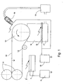
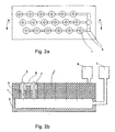
- a basic variant of the device of the present invention includes a high-voltage electrode-collector 1, manufactured as bath, filled with the polymer solution and provided with a base 2 and a cover 2'.
- the electrode-collector is connected to a feeder 3 ( Figure 2B) by a flexible pipe, installed so as to allow vertical movement, and a source 4 of high voltage of negative polarity.
- Precipitation electrode 10 is grounded. Shafts 11 and 12, connected to an electrical motor (not depicted on the pictures), are responsible for driving precipitation electrode 10, keeping precipitation electrode 10 under tension, and preliminary compression of the material on precipitation electrode 10. Part of precipitation electrode 10 is wound around shaft 13, which has a large diameter, and is thus immersed in the rectangular cavity of the electrified aerosol generator.
- the cavity of the electrified aerosol generator is divided into two sections by a porous conducting partition 15. The latter is connected, to a high-voltage source 16 of positive polarity.
- the lower part 14 of the electrified aerosol generator, forming pressure chamber 17, is connected to a compressor (not shown on drawings).
- a micro-dispersible filler is poured onto the surface of the porous partition 15 in the upper part of the generator.
- the entire device depicted in Figure 1 is contained in a hermetically sealed container, provided with a suction unit and a settling chamber for trapping and re-circulation of the solvent vapors (not shown an drawings).
- the electrified aerosol generator may also be implemented in the form of a slot sprayer 18, connected by a pipe to a dry powder ejection feeder 19 and a source of positive high voltage 16.
- the use of the slot sprayer with a charging of aerosol in the field of the corona discharge is preferred in the case of metallic powders (including graphite powder) and powders that are not easily fluidized.
- the direction of fiber feeding on the vertical surface may be reversed, and the dimensions of the electrode-collector and the number of capillaries may be minimized with the help of the device depicted in Figure 3.
- the device consists of an electrode-collector frame 20, manufactured from a dielectric material and having a central channel 21, for example, of cylindrical shape. This channel is connected by a pipe to a feeder (not shown on the drawing) and is provided with aperture 22 to facilitate exchange of gases with the atmosphere.
- a busbar 23 with spinnerets 5 and nozzles having capillary apertures is installed in the lower part of frame 20. The nozzles are connected to a source of high voltage (not shown on the drawing).
- Cover 24 with apertures 25 is placed before the busbar. Nozzles 6 are placed in these apertures with coaxial clearance.
- the internal surface of the cover and busbar form a cavity 26, which is connected to a saturator (not shown on drawing) by a pipe.
- a dielectric flange 28 serves as a base for a perforated grounded plate 27, which is installed, with a certain clearance C, parallel to the surfaces of the electrode-collector 20 and the busbar 23.
- Plate 27 rests on the flange in such a way as to provide for vertical movement for regulation of the size of the clearance C.
- Apertures 29 of the perforated plate are co-axial to the apertures of electrode-collector's nozzles.
- the internal surface of perforated plate 27 and busbar 23 form a cavity 26, which is connected by a pipe to a saturator.
- the proposed device in its basic form functions as follows: From feeder 3 ( Figure 2B), the polymer solution runs into electrode-collector bath 1, and under the action of hydrostatic pressure the polymer solution begins to be extruded through the capillary apertures of nozzles 6. As soon as a meniscus forms in the polymer solution, the process of solvent evaporation starts. This process is accompanied by the creation of capsules with a semi-rigid envelope, the dimensions of which are determined, on the one hand, by hydrostatic pressure, the concentration of the original solution and the value of the surface tension, and, on the other hand, by the concentration of the solvent vapor in the area of the capillary apertures. The latter parameter is optimized by choice of the area of free evaporation from cover 2' and of the solvent temperature.
- these jets start to lose solvent and form fibers that are chaotically precipitated on the surface of the moving precipitation electrode 10, forming a sheet-like fiber matrix. Since the polymer fiber posses high surface electric resistance and the volume of material in physical contact with precipitation electrode surface is small, the fiber matrix preserves the negative electric charge for a long time.
- the micro-dispersible filler When compressed air is fed into pressure chamber 17 of electrified aerosol generator 14 and high-voltage source 16 is switched on, the micro-dispersible filler becomes fluidized and acquires a positive electric charge. Under the action of electric and aerodynamic forces, the filler particles move to the surface of precipitation electrode 10, which holds the fiber matrix. As a result of the action of Coulombic forces, the filler particles interact with the fiber matrix, penetrate its structure, and form a composite material.
- micro-dispersible powders from the following materials may be used as fillers: a polymer of the same chemical composition as that in the matrix, polymer latexes, glass, or Teflon, as well as active fillers that lead to the production of composite microfiltering materials with new consumer properties. These new materials may find application as adsorbents, indicators, catalysts, ion-exchange resins, pigments bactericides, etc.
- an electrified aerosol generator as described above with the fluidized layer, facilitates high productivity of the process and product homogeneity.
- metallic powders particularly catalytic metals
- a slot sprayer 18 as the electrified aerosol generator ( Figure 1).
- compressed air from a compressor is fed into the dry powder feeder and the high voltage source is switched on, the powdered filler is ejected into slot sprayer 18.
- the aerosol cloud coming out of the sprayer apertures becomes charged in the unipolar corona discharge field, and under the action of electric and aerodynamic forces is transferred to the precipitation electrode, where it interacts with the fiber matrix as described above.
- the optimal electric field strength, both between electrode-collector I and precipitation electrode 10, and between the electrified aerosol generator and precipitation electrode 10, is between about 2.5 KV/cm and about 4 KV/cm.
- An increase in the average intensity and heterogeneity of the electric field, leading to corona discharge, may be realized by installing, in the inter-electrode-interval, one or more grounded electrodes manufactured, for instance, in the form of wires.
- This solution facilitates an increase in the productivity of the process by 1.5-2 times, but it does not lead to formation of short fibers with, varying strength and size parameters.
- the negative effect of using a linear grounded electrode instead of a planar grounded electrode, thereby producing an inhomogeneous electrical field, may be reduced by increasing the solvent vapor concentration in the fiber-formation area, which is difficult in open devices and increases solvent consumption and danger of fire.
- the present invention may be used to produce the polymer fiber structure from a much wider range of polymers than is possible using the prior art of US 2,349,950.
- Polymers amenable to the present invention include polysulfone, polyphenyl sulfone, polyether sulfone, polycarbonate in general, ABS; polystyrene, polyvynilidene fluoride, postchlorinated polyvinyl chloride and polyacrilonitrile.
- Suitable solvents include, inter alia , chloroform, benzene, acetone and dimethylformamide.
- the optimal concentration of the solution depends on the specific polymer and solvent used. Generally, the higher the concentration of polymer in the solution, the higher the process yield and the lower the product porosity.
- Amine salts such as tetraethyl ammonium bromide and benzyltriethylammonium bromide, arc used to regulate the conductivity of the polymer solution.
- Small amounts of high molecular weight (order of 500,000) polyoxyalkylene additives such as polyethylene glycol and polyvinyl pyrrolidone promote the formation of the polymer solution jets by reducing intermolecular friction.
- Surfactants such as dimethylmidazole and ethoxytrimethylsilane enhance fiber thickness and uniformity.
- the scope of the present invention includes the manufacture of the polymer fiber structure from a liquefied polymer, and not just from a polymer solution.
- a liquefied polymer is meant a polymer put into a liquid state by any means, including dissolving the polymer in a solvent, as described above, and melting the polymer.
- the scope of the present invention includes the formation of a surface on the liquefied polymer, of sufficient curvature to initiate the process discussed above of the charged capsules, leading to the formation of the jets of liquefied polymer that turn into fibers and precipitate onto precipitation electrode 10.
- the liquefied polymer is a polymer solution
- the fibers are formed by evaporation of the solvent.
- the liquefied polymer is a melt
- the fibers are formed by solidification of the jets.
- the highly curved surfaces are the menisci of polymer solution emerging from nozzles 6.
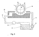
- Figure 5 illustrates a variant of electrode-collector I in which the polymer solution, stored in a tank 33, is pumped by a pump 32 through a feed pipe 31 to a delivery chamber 36.
- Rotatably mounted in delivery chamber 36 is a circular wheel 30 made of an electrically conductive material.
- Mounted on rim 38 of wheel 30 are triangular protrusions 40 made of a material that is wetted by the polymer solution. Tips 42 of protrusions 40 point radially outward from wheel 38.
- Wheel 38 is charged negatively by source 4.
- FIG 6 is a partial illustration, in cross-section, similar to the cross-section of Figure 2B, of a variant of electrode-collector I in which nozzles 6 are replaced by reciprocating needles 40, made of an electrically conductive material that is wetted by the polymer solution.
- Each needle 40 is provided with a mechanism 42 for raising and lowering needle 40.
- the sharpened tip 44 thereof is wetted and coated by the polymer solution.
- the surface of the polymer solution is highly curved at tip 44.
- the high voltage difference between needle 40 and precipitation electrode 10 causes jets of the polymer solution to emerge from the polymer solution surrounding tip 44 and to stream towards precipitation electrode 10.
- only needles 40, and hence the polymer solution thereon are negatively charged by source 4.
- Speaker 50 of a system for producing acoustical vibrations in the air above electrode-collector 1.
- Speaker 50 emits a tone of a single frequency, preferably in the range between about 5000 Hz and about 30,000 Hz, towards needles 40.
- the vibrations thus induced in the highly curved surfaces of the polymer solution on tips 44 have been found to stimulate the emission of jets of polymer solution towards precipitation collector 10.
Landscapes
- Engineering & Computer Science (AREA)
- Textile Engineering (AREA)
- Mechanical Engineering (AREA)
- Nonwoven Fabrics (AREA)
- Filtering Materials (AREA)
- Spinning Methods And Devices For Manufacturing Artificial Fibers (AREA)
- Glass Compositions (AREA)
- Chemical Or Physical Treatment Of Fibers (AREA)
Claims (2)
- Eine Vlies-Verbundfaserstruktur, erhaltbar durch ein Verfahren des Formens eines Polymers zu besagter Vlies-Verbundfaserstruktur, wobei das Verfahren die Schritte umfasst des:(a) Verflüssens des Polymers, dadurch Herstellens eines verflüssigten Polymers;(b) Vorsehens einer im Wesentlichen planaren Niederschlagselektrode (10);(c) Aufladens besagten verflüssigten Polymers auf ein erstes elektrisches Potential in Bezug auf besagte Niederschlagselektrode (10);(d) Bildens einer Oberfläche auf besagtem verflüssigtem Polymer von ausreichend hoher Krümmung, um das Anziehen wenigstens eines geladenen Strahls besagten verflüssigten Polymers zu besagter Niederschlagselektrode (10) durch besagte erste elektrische Potentialdifferenz zu verursachen, wodurch eine geladene Matrix von Polymerfasern an besagter Niederschlagselektrode (10) gebildet wird; und
gekennzeichnet durch(e) Zuführen eines Aerosols von geladenem Füllstoffpulver zu besagter Niederschlagselektrode (10), auf eine Weise, dass elektrische Kräfte zwischen besagtem geladenen Füllstoffpulver und besagter geladener Matrix besagtes geladenes Füllstoffpulver gleichförmig innerhalb von eine minimale Volumendichte aufweisenden Mikrozonen besagter geladener Matrix verteilen, wodurch sie ein Verbundmaterial damit bilden. - Die Vlies-Verbundfaserstruktur von Anspruch 1, wobei besagte Verflüssigung durch Auflösen des Polymers in einem Lösungsmittel bewirkt wird, wodurch eine Polymerlösung erzeugt wird, und das Verfahren weiter den Schritt umfasst des:(f) besagter Polymerlösung Zusetzens eines Additivs, gewählt aus der aus Aminsalzen, Polyoxyalkylenen und grenzflächenaktiven Stoffen bestehenden Gruppe.
Applications Claiming Priority (3)
| Application Number | Priority Date | Filing Date | Title |
|---|---|---|---|
| IL1980996 | 1996-12-11 | ||
| IL1980996 | 1996-12-11 | ||
| EP97946792A EP0952893B1 (de) | 1996-12-11 | 1997-12-09 | Verfahren und vorrichtung zur herstellung von kompositfiltermaterialien |
Related Parent Applications (1)
| Application Number | Title | Priority Date | Filing Date |
|---|---|---|---|
| EP97946792A Division EP0952893B1 (de) | 1996-12-11 | 1997-12-09 | Verfahren und vorrichtung zur herstellung von kompositfiltermaterialien |
Publications (2)
| Publication Number | Publication Date |
|---|---|
| EP1443136A1 EP1443136A1 (de) | 2004-08-04 |
| EP1443136B1 true EP1443136B1 (de) | 2006-09-27 |
Family
ID=37102335
Family Applications (1)
| Application Number | Title | Priority Date | Filing Date |
|---|---|---|---|
| EP04003231A Expired - Lifetime EP1443136B1 (de) | 1996-12-11 | 1997-12-09 | Kompositfiltermaterialien |
Country Status (3)
| Country | Link |
|---|---|
| EP (1) | EP1443136B1 (de) |
| AT (1) | ATE340887T1 (de) |
| DE (1) | DE69736753T2 (de) |
Family Cites Families (2)
| Publication number | Priority date | Publication date | Assignee | Title |
|---|---|---|---|---|
| GB1522605A (en) * | 1974-09-26 | 1978-08-23 | Ici Ltd | Preparation of fibrous sheet product |
| DE4327595A1 (de) * | 1993-08-17 | 1995-02-23 | Hoechst Ag | Zusammensetzungen mit verbesserten elektrostatischen Eigenschaften enthaltend aromatische Polyamide, daraus hergestellte geformte Gebilde sowie deren Verwendung und Verfahren zu ihrer Herstellung |
-
1997
- 1997-12-09 AT AT04003231T patent/ATE340887T1/de not_active IP Right Cessation
- 1997-12-09 DE DE69736753T patent/DE69736753T2/de not_active Expired - Lifetime
- 1997-12-09 EP EP04003231A patent/EP1443136B1/de not_active Expired - Lifetime
Also Published As
| Publication number | Publication date |
|---|---|
| EP1443136A1 (de) | 2004-08-04 |
| DE69736753D1 (de) | 2006-11-09 |
| DE69736753T2 (de) | 2007-08-16 |
| ATE340887T1 (de) | 2006-10-15 |
Similar Documents
| Publication | Publication Date | Title |
|---|---|---|
| EP0952893B1 (de) | Verfahren und vorrichtung zur herstellung von kompositfiltermaterialien | |
| EP1059106B1 (de) | Vorrichtung und Verfahren zur Herstellung eines Filtermaterials | |
| EP2222903B1 (de) | Zentrifugales spun-nanofaserlösungsverfahren | |
| US8241537B2 (en) | Method for manufacturing polymeric fibrils | |
| KR101417142B1 (ko) | 용액 방사 섬유 제조방법 | |
| US8801998B2 (en) | Method for producing a polyamide nanofiber product by electrospinning | |
| US20060012084A1 (en) | Electroblowing web formation process | |
| CN1284888C (zh) | 利用电荷感应纺丝的高分子纤维网制造装置和其制造方法 | |
| EP1443136B1 (de) | Kompositfiltermaterialien | |
| US9903050B2 (en) | Formation of core-shell fibers and particles by free surface electrospinning | |
| EP1468715B1 (de) | Filtermaterial und Vorrichtung und Verfahren zur Herstellung | |
| KR100595487B1 (ko) | 고분자 입자 및 그의 제조방법 | |
| Ramesh et al. | Characterization of the Metal-Organic Framework Nanofibers Prepared via Electrospinning | |
| JP4979203B2 (ja) | 吸着構造体およびその製造方法 | |
| KR20050038672A (ko) | 복합재료 다공성 연속막 및 그 제조방법 | |
| Roso et al. | Electrospun nanofibrous membranes | |
| Karthik et al. | fibre composites | |
| WO2006006746A1 (en) | Polymer particles, and a method for manufacturing the same |
Legal Events
| Date | Code | Title | Description |
|---|---|---|---|
| PUAI | Public reference made under article 153(3) epc to a published international application that has entered the european phase |
Free format text: ORIGINAL CODE: 0009012 |
|
| 17P | Request for examination filed |
Effective date: 20040213 |
|
| AC | Divisional application: reference to earlier application |
Ref document number: 0952893 Country of ref document: EP Kind code of ref document: P |
|
| AK | Designated contracting states |
Kind code of ref document: A1 Designated state(s): AT BE CH DE DK ES FI FR GB GR IE IT LI LU MC NL PT SE |
|
| AKX | Designation fees paid |
Designated state(s): AT BE CH DE DK ES FI FR GB GR IE IT LI LU MC NL PT SE |
|
| 17Q | First examination report despatched |
Effective date: 20050321 |
|
| GRAP | Despatch of communication of intention to grant a patent |
Free format text: ORIGINAL CODE: EPIDOSNIGR1 |
|
| GRAS | Grant fee paid |
Free format text: ORIGINAL CODE: EPIDOSNIGR3 |
|
| GRAA | (expected) grant |
Free format text: ORIGINAL CODE: 0009210 |
|
| AC | Divisional application: reference to earlier application |
Ref document number: 0952893 Country of ref document: EP Kind code of ref document: P |
|
| AK | Designated contracting states |
Kind code of ref document: B1 Designated state(s): AT BE CH DE DK ES FI FR GB GR IE IT LI LU MC NL PT SE |
|
| PG25 | Lapsed in a contracting state [announced via postgrant information from national office to epo] |
Ref country code: IT Free format text: LAPSE BECAUSE OF FAILURE TO SUBMIT A TRANSLATION OF THE DESCRIPTION OR TO PAY THE FEE WITHIN THE PRESCRIBED TIME-LIMIT;WARNING: LAPSES OF ITALIAN PATENTS WITH EFFECTIVE DATE BEFORE 2007 MAY HAVE OCCURRED AT ANY TIME BEFORE 2007. THE CORRECT EFFECTIVE DATE MAY BE DIFFERENT FROM THE ONE RECORDED. Effective date: 20060927 Ref country code: AT Free format text: LAPSE BECAUSE OF FAILURE TO SUBMIT A TRANSLATION OF THE DESCRIPTION OR TO PAY THE FEE WITHIN THE PRESCRIBED TIME-LIMIT Effective date: 20060927 Ref country code: NL Free format text: LAPSE BECAUSE OF FAILURE TO SUBMIT A TRANSLATION OF THE DESCRIPTION OR TO PAY THE FEE WITHIN THE PRESCRIBED TIME-LIMIT Effective date: 20060927 Ref country code: BE Free format text: LAPSE BECAUSE OF FAILURE TO SUBMIT A TRANSLATION OF THE DESCRIPTION OR TO PAY THE FEE WITHIN THE PRESCRIBED TIME-LIMIT Effective date: 20060927 Ref country code: FI Free format text: LAPSE BECAUSE OF FAILURE TO SUBMIT A TRANSLATION OF THE DESCRIPTION OR TO PAY THE FEE WITHIN THE PRESCRIBED TIME-LIMIT Effective date: 20060927 |
|
| REG | Reference to a national code |
Ref country code: GB Ref legal event code: FG4D |
|
| REG | Reference to a national code |
Ref country code: CH Ref legal event code: EP |
|
| REG | Reference to a national code |
Ref country code: IE Ref legal event code: FG4D |
|
| REF | Corresponds to: |
Ref document number: 69736753 Country of ref document: DE Date of ref document: 20061109 Kind code of ref document: P |
|
| PG25 | Lapsed in a contracting state [announced via postgrant information from national office to epo] |
Ref country code: DK Free format text: LAPSE BECAUSE OF FAILURE TO SUBMIT A TRANSLATION OF THE DESCRIPTION OR TO PAY THE FEE WITHIN THE PRESCRIBED TIME-LIMIT Effective date: 20061227 Ref country code: SE Free format text: LAPSE BECAUSE OF FAILURE TO SUBMIT A TRANSLATION OF THE DESCRIPTION OR TO PAY THE FEE WITHIN THE PRESCRIBED TIME-LIMIT Effective date: 20061227 |
|
| PG25 | Lapsed in a contracting state [announced via postgrant information from national office to epo] |
Ref country code: ES Free format text: LAPSE BECAUSE OF FAILURE TO SUBMIT A TRANSLATION OF THE DESCRIPTION OR TO PAY THE FEE WITHIN THE PRESCRIBED TIME-LIMIT Effective date: 20070107 |
|
| NLV1 | Nl: lapsed or annulled due to failure to fulfill the requirements of art. 29p and 29m of the patents act | ||
| PG25 | Lapsed in a contracting state [announced via postgrant information from national office to epo] |
Ref country code: PT Free format text: LAPSE BECAUSE OF FAILURE TO SUBMIT A TRANSLATION OF THE DESCRIPTION OR TO PAY THE FEE WITHIN THE PRESCRIBED TIME-LIMIT Effective date: 20070313 |
|
| EN | Fr: translation not filed | ||
| PLBE | No opposition filed within time limit |
Free format text: ORIGINAL CODE: 0009261 |
|
| STAA | Information on the status of an ep patent application or granted ep patent |
Free format text: STATUS: NO OPPOSITION FILED WITHIN TIME LIMIT |
|
| 26N | No opposition filed |
Effective date: 20070628 |
|
| PGFP | Annual fee paid to national office [announced via postgrant information from national office to epo] |
Ref country code: MC Payment date: 20071213 Year of fee payment: 11 |
|
| PGFP | Annual fee paid to national office [announced via postgrant information from national office to epo] |
Ref country code: CH Payment date: 20071217 Year of fee payment: 11 |
|
| PG25 | Lapsed in a contracting state [announced via postgrant information from national office to epo] |
Ref country code: FR Free format text: LAPSE BECAUSE OF FAILURE TO SUBMIT A TRANSLATION OF THE DESCRIPTION OR TO PAY THE FEE WITHIN THE PRESCRIBED TIME-LIMIT Effective date: 20070525 Ref country code: GR Free format text: LAPSE BECAUSE OF FAILURE TO SUBMIT A TRANSLATION OF THE DESCRIPTION OR TO PAY THE FEE WITHIN THE PRESCRIBED TIME-LIMIT Effective date: 20061228 |
|
| PG25 | Lapsed in a contracting state [announced via postgrant information from national office to epo] |
Ref country code: LU Free format text: LAPSE BECAUSE OF NON-PAYMENT OF DUE FEES Effective date: 20061209 |
|
| PG25 | Lapsed in a contracting state [announced via postgrant information from national office to epo] |
Ref country code: FR Free format text: LAPSE BECAUSE OF FAILURE TO SUBMIT A TRANSLATION OF THE DESCRIPTION OR TO PAY THE FEE WITHIN THE PRESCRIBED TIME-LIMIT Effective date: 20060927 |
|
| PG25 | Lapsed in a contracting state [announced via postgrant information from national office to epo] |
Ref country code: MC Free format text: LAPSE BECAUSE OF NON-PAYMENT OF DUE FEES Effective date: 20081231 |
|
| REG | Reference to a national code |
Ref country code: CH Ref legal event code: PL |
|
| PGFP | Annual fee paid to national office [announced via postgrant information from national office to epo] |
Ref country code: IE Payment date: 20071220 Year of fee payment: 11 |
|
| PG25 | Lapsed in a contracting state [announced via postgrant information from national office to epo] |
Ref country code: CH Free format text: LAPSE BECAUSE OF NON-PAYMENT OF DUE FEES Effective date: 20081231 Ref country code: LI Free format text: LAPSE BECAUSE OF NON-PAYMENT OF DUE FEES Effective date: 20081231 Ref country code: IE Free format text: LAPSE BECAUSE OF NON-PAYMENT OF DUE FEES Effective date: 20081209 |
|
| PGFP | Annual fee paid to national office [announced via postgrant information from national office to epo] |
Ref country code: GB Payment date: 20101221 Year of fee payment: 14 |
|
| PGFP | Annual fee paid to national office [announced via postgrant information from national office to epo] |
Ref country code: DE Payment date: 20101222 Year of fee payment: 14 |
|
| GBPC | Gb: european patent ceased through non-payment of renewal fee |
Effective date: 20111209 |
|
| REG | Reference to a national code |
Ref country code: DE Ref legal event code: R119 Ref document number: 69736753 Country of ref document: DE Effective date: 20120703 |
|
| PG25 | Lapsed in a contracting state [announced via postgrant information from national office to epo] |
Ref country code: GB Free format text: LAPSE BECAUSE OF NON-PAYMENT OF DUE FEES Effective date: 20111209 Ref country code: DE Free format text: LAPSE BECAUSE OF NON-PAYMENT OF DUE FEES Effective date: 20120703 |