EP1442964A2 - Cross car beam for vehicle - Google Patents
Cross car beam for vehicle Download PDFInfo
- Publication number
- EP1442964A2 EP1442964A2 EP04001730A EP04001730A EP1442964A2 EP 1442964 A2 EP1442964 A2 EP 1442964A2 EP 04001730 A EP04001730 A EP 04001730A EP 04001730 A EP04001730 A EP 04001730A EP 1442964 A2 EP1442964 A2 EP 1442964A2
- Authority
- EP
- European Patent Office
- Prior art keywords
- cylindrical body
- car beam
- cross car
- vehicle
- driver
- Prior art date
- Legal status (The legal status is an assumption and is not a legal conclusion. Google has not performed a legal analysis and makes no representation as to the accuracy of the status listed.)
- Granted
Links
- 238000004378 air conditioning Methods 0.000 claims abstract description 7
- 239000000057 synthetic resin Substances 0.000 claims description 12
- 229920003002 synthetic resin Polymers 0.000 claims description 12
- 239000000470 constituent Substances 0.000 claims description 8
- 241000283690 Bos taurus Species 0.000 claims description 5
- 230000002093 peripheral effect Effects 0.000 claims description 3
- 238000007664 blowing Methods 0.000 claims description 2
- 239000011347 resin Substances 0.000 description 29
- 229920005989 resin Polymers 0.000 description 29
- 238000000465 moulding Methods 0.000 description 19
- 230000003014 reinforcing effect Effects 0.000 description 17
- 239000000463 material Substances 0.000 description 12
- 238000005266 casting Methods 0.000 description 8
- 229910000831 Steel Inorganic materials 0.000 description 7
- 239000010959 steel Substances 0.000 description 7
- 238000003780 insertion Methods 0.000 description 6
- 230000037431 insertion Effects 0.000 description 6
- 238000004519 manufacturing process Methods 0.000 description 6
- 230000004048 modification Effects 0.000 description 6
- 238000012986 modification Methods 0.000 description 6
- 238000001746 injection moulding Methods 0.000 description 5
- 230000015572 biosynthetic process Effects 0.000 description 4
- 238000003466 welding Methods 0.000 description 4
- PWHULOQIROXLJO-UHFFFAOYSA-N Manganese Chemical compound [Mn] PWHULOQIROXLJO-UHFFFAOYSA-N 0.000 description 3
- 229910052748 manganese Inorganic materials 0.000 description 3
- 239000011572 manganese Substances 0.000 description 3
- 238000000034 method Methods 0.000 description 3
- 239000000835 fiber Substances 0.000 description 2
- 238000009434 installation Methods 0.000 description 2
- 239000007787 solid Substances 0.000 description 2
- 102000000591 Tight Junction Proteins Human genes 0.000 description 1
- 108010002321 Tight Junction Proteins Proteins 0.000 description 1
- 230000007547 defect Effects 0.000 description 1
- 230000000694 effects Effects 0.000 description 1
- 238000010438 heat treatment Methods 0.000 description 1
- WPBNNNQJVZRUHP-UHFFFAOYSA-L manganese(2+);methyl n-[[2-(methoxycarbonylcarbamothioylamino)phenyl]carbamothioyl]carbamate;n-[2-(sulfidocarbothioylamino)ethyl]carbamodithioate Chemical compound [Mn+2].[S-]C(=S)NCCNC([S-])=S.COC(=O)NC(=S)NC1=CC=CC=C1NC(=S)NC(=O)OC WPBNNNQJVZRUHP-UHFFFAOYSA-L 0.000 description 1
- 239000012260 resinous material Substances 0.000 description 1
- 230000000630 rising effect Effects 0.000 description 1
- 210000001578 tight junction Anatomy 0.000 description 1
Images







Classifications
-
- B—PERFORMING OPERATIONS; TRANSPORTING
- B62—LAND VEHICLES FOR TRAVELLING OTHERWISE THAN ON RAILS
- B62D—MOTOR VEHICLES; TRAILERS
- B62D25/00—Superstructure or monocoque structure sub-units; Parts or details thereof not otherwise provided for
- B62D25/08—Front or rear portions
- B62D25/14—Dashboards as superstructure sub-units
- B62D25/145—Dashboards as superstructure sub-units having a crossbeam incorporated therein
-
- B—PERFORMING OPERATIONS; TRANSPORTING
- B62—LAND VEHICLES FOR TRAVELLING OTHERWISE THAN ON RAILS
- B62D—MOTOR VEHICLES; TRAILERS
- B62D25/00—Superstructure or monocoque structure sub-units; Parts or details thereof not otherwise provided for
- B62D25/08—Front or rear portions
- B62D25/14—Dashboards as superstructure sub-units
- B62D25/142—Dashboards as superstructure sub-units having ventilation channels incorporated therein
Definitions
- the present invention relates to a cross car beam for a vehicle.
- the cross car beam is arranged inside an automotive instrument panel while fixing both car beam's ends in the vehicle-width direction to pillar members on both lateral sides of a vehicle body or a dash panel.
- the cross car beam performs a role to support a steering unit, the instrument panel and so on. Therefore, in view of ensuring beam's rigidity meeting such a role, the cross car beam is generally made from high rigid materials, such as steels and manganese.
- Japanese Patent Application Laid-open No. 2002-211441 discloses a cross car beam made of synthetic resin.
- the disclosed cross car beam is provided, on its attachment surfaces to the vehicle body, with additional ribs.
- the attachment surfaces are increased in thickness. In this way, the attachment surfaces are reinforced to increase the strength of the cross car beam.
- the cross car beam has its intermediate part (in the vehicle-width direction) supported by a floor panel etc. on the side of the vehicle body through the intermediary of a support stay.
- a cross car beam is provided with a high rigid attachment part for fixation with a support member on the side of the vehicle body.
- This attachment part is formed by high rigid material, such as steel and manganese.
- the attachment part of the cross car beam is fixed to an end of the support stay (as the above support member), while the other end of the support stay is fixed to a floor panel of the vehicle body. In this way, the cross car beam is carried by the vehicle body (see Japanese Patent Application Laid-open No. 2002-284018).
- a supporting structure for a cross car beam in accordance with the above prior art has various problems to be solved.
- an air conditioning unit for feeding warm or cool wind into a vehicle cabin is arranged independently of such a cross car beam (see Japanese Patent Application Laid-open No. 2001-328421).
- Japanese Patent Application Laid-open No. 2002-284018 discloses a cross car beam that is equipped, on its peripheral surface, with steering support brackets for supporting a steering unit.
- attachment bolts for supporting the steering unit are attached to the steering support brackets of the cross car beam.
- the steering support brackets support the steering unit through the attachment bolts.
- the steering unit is generally heavy, it is necessary for the steering support brackets to have great mechanical strength.
- the cross car beam is arranged inside the instrument panel generally.
- the cross car beam is generally provided, on the assistant driver's side, with an air-bag attachment member for installation of an air-bag unit.
- This air-bag attachment member has to be provided with a designated strength because it may be subjected, at a vehicle collision, to a collision impact transmitted from a passenger through an air bag.
- the cross car beam and the air-bag attachment member are formed by the use of high rigid materials, such as steels (see Japanese Patent Application Laid-open No. 10-119684).
- a cross car beam of the present invention comprises: a first cylindrical body arranged along a vehicle-width direction so as to extend from a driver's side to an assistant driver's side; a second cylindrical body arranged on the outer circumference of a first cylindrical body's part on the driver's side and wound around the first cylindrical body in a tight manner, thereby providing the cross car beam with a double-pipe structure of the first cylindrical body and the second cylindrical body.
- At least either one of an end of the first cylindrical body on an assistant driver's side thereof and an end of the second cylindrical body on a driver's side thereof is provided with an attachment part which is formed to be fixable to a constituent member of a vehicle body, the attachment part having a honeycomb structure.
- the attachment part is formed to be a honeycomb structure, it is possible to improve the mechanical strength of the attachment part without rises in weight and material cost. Consequently, even if the cross car beam is made of synthetic resin, it is possible to attach the cross car beam to a constituent of the vehicle body certainly.
- the honeycomb structure has a plurality of plate ribs formed so as to extend from an axis of the first cylindrical body or an axis of the second cylindrical body radially.
- the attachment part is provided in the form of a honeycomb structure of the plate ribs, it is possible to disperse a torsion torque inputted to the cross car beam into the plate ribs effectively and also possible to transmit the torsion torque to the vehicle body effectively.
- the first cylindrical body and the second cylindrical body may be respectively provided, on their circumferential surfaces close to the attachment part, with vent blowout ports that communicate with the interior of the first cylindrical body and the interior of the second cylindrical body, respectively.
- the cross car beam may further comprises a steering supporting part arranged in the vicinity of the attachment part to support a steering unit of the vehicle.
- the cross car beam is capable of supporting the steering unit certainly in spite of vibrations during a vehicle's traveling.
- the cross car beam further comprises a rind member adapted so as to envelop the outer periphery of the end of the first cylindrical member on the assistant driver's side, wherein the attachment part is arranged on an end of the rind member and the second cylindrical member is provided, on the end on the driver's side, with another attachment part.
- the cross car beam may further comprise a support member, wherein the second cylindrical body is provided, on a periphery thereof, with a rib having an attachment part for the support member, and the support member has one end attached to the attachment part and the other end fixed to a constituent member of a vehicle body, whereby an intermediate part of the cross car beam in a vehicle-width direction is supported by the constituent member through the support member.
- the rib is provided with the attachment part for the support member, it is possible to improve the mechanical strength of the above attachment part without rises in weight and material cost about the cross car beam. Consequently, even if the cross car beam is made of synthetic resin, it can be supported by a constituent of the vehicle body certainly.
- the rib may be formed on an inside end of the second cylindrical body in a vehicle-width direction.
- the attachment part for the supporting member may be arranged, in the rib, on the lower side of the second cylindrical body.
- the supporting member supports the lower side of the cross car beam, the weight of the cross car beam is transmitted to the supporting member effectively, whereby the cross car beam can be held by the vehicle body certainly.
- the first cylindrical body may be provided, on its intermediate part in a vehicle-width direction, with an opening for connection with an air conditioning unit.
- the opening for connection with the air conditioning unit is formed on the center side of the first cylindrical body in the vehicle-width direction, it is possible to utilize part of the cross car beam as an air duct through which warm and cool air from the air conditioning unit is blown into the vehicle cabin.
- first cylindrical body may be provided, on a driver's side thereof, with a steering supporting part to support a steering unit of the vehicle and furthermore, the first cylindrical body's part close to a steering supporting part may be formed to provide the double-pipe structure together with the second cylindrical body.
- the same structure allows the heavy steering unit to be supported stably.
- first cylindrical body and the second cylindrical body may be respectively made of synthetic resin.
- the strength of synthetic resin forming the second cylindrical body is established larger than that of synthetic resin forming the first cylindrical body.
- the first cylindrical body may be formed by an upper halved member on the upside of the vehicle and a lower halved member on the downside of the vehicle, both of which are welded to each other.
- the first cylindrical body is formed by both of the upper halved member and the lower halved member, the constitution allows a load applied on the cross car beam to be received and caught effectively.
- the cross car beam carries a steering unit, an instrument panel, etc., so that an external force (load) therefrom acts downwardly of the vehicle.
- the first cylindrical body of the car beam is formed by the upper and lower halved members each having respective welding surfaces arranged generally horizontally, the strength of the cross car beam against the external force is remarkably increased at the above welding surfaces.
- the second cylindrical body may be provided with a steering support member projecting in a fore-and-aft direction of the vehicle and furthermore, the steering support member may be formed by a plate extending from the periphery of the second cylindrical body in the fore-and-aft direction of the vehicle and a sidewall part formed around the plate.
- the integral arrangement of the steering support member with the cross car beam could improve the attaching strength of the steering support member.
- the integral arrangement of the steering support member with the cross car beam could improve the attaching strength of the steering support member.
- a steering unit may be supported on the lower surface of the steering support member, wherein the double-pipe structure's part in the vicinity of the steering support member has a vent blowout port formed in a manner that its upper part opens, thereby blowing out wind against a vehicle cabin.
- the rigidity of the cross car beam itself is improved by the steering support member. Therefore, despite that the vent blowout port is formed in the cross car beam, it is possible for the cross car beam to maintain its strength against vertical vibrations through the steering unit because the blowout port is not positioned in a vertical wall of the car beam but in its upper surface opposite to the lower surface to carry the steering unit.
- the steering support member may be arranged on the peripheral surface of the second cylindrical body, on each of the front and rear sides of the vehicle.
- the steering support member may have a fastening member molded in one body therewith to project downwardly, and the steering unit is attached to the fastening member, thereby supporting the steering unit through the steering support member.
- the first cylindrical body may be formed by halved members and further, one of the halved members may be provided with an air-bag attachment member.
- the first cylindrical body may be formed so that its upper surface on an assistant driver's side becomes higher than the upper surface on a driver's side, the first cylindrical body is formed by an upper halved member on the upside of the vehicle and a lower halved member on the downside of the vehicle, both of which are welded to each other, the air-bag attachment member is provided on the assistant driver's side of the lower halved member and that a parting line between the upper halved member and the lower halved member is arranged, on the driver's side, at the central part of the first cylindrical body in a vertical direction of the vehicle and also arranged, on the assistant driver's side, above the air-bag attachment member.
- the parting line on the assistant driver's side is arranged above the air-bag attachment member, it is possible to form the air-bag attachment member itself in one body, whereby its strength can be improved. Consequently, it is possible to provide the first cylindrical body with enough rigidity to cope with an external load that might be inputted to the air-bag attachment member through an air bag at a vehicle collision.
- parting line on the assistant driver's side may be arranged along the upper surface of the first cylindrical body.
- the upper surface of the first cylindrical body on the assistant driver's side may form a part of a surface of an instrument panel.
- the upper surface of the upper halved member which is excellent in terms of molding quality, as part of the surface of the instrument panel. Consequently, it is possible to lighten the instrument panel with a reduction of material cost.
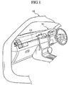
- Fig. 1 shows the interior of a vehicle cabin of a vehicle body 10 on the application of a cross car beam of the first embodiment of the invention.
- an instrument panel 11 On the front side of the vehicle cabin, there is arranged an instrument panel 11. Inside the instrument panel 11, in other words, on the front side of the panel 11, a cross car beam 12 is arranged so as to extend from the driver's side (or driver's seat side) to the assistant driver's side (or assistant driver's seat side) of a vehicle.
- the cross car beam 12 is provided, on both right and left sides thereof, with attachment parts 13, 13 each having fitting faces 61.
- the fitting faces 61 are respectively provided with bolt holes 62.
- a dash lower panel 14 is arranged in front of the cross car beam 12.
- the dash floor panel 14 is provided, on both sides thereof in a vehicle-width direction, with side panel parts 15a, 15a each having attachment flanges 15, 15 folded to extend from their rear edges of the panels 15a, 15a to an out-vehicle direction.
- the above attachment parts 13, 13 of the cross car beam 12 are fastened to the attachment flanges 15, 15 by means of bolts 43.
- the cross car beam 12 is supported, on its center side, by an upper surface 18a of a tunnel part 18 of a floor panel through a support stay 16 and a L-shaped attachment bracket 17.
- an attachment bracket 21 is fixed to the outer circumferential face (front-side) of the cross car beam 12.
- the attachment bracket 21 is attached to a rear face 14a of the dash lower panel 14 through a support bracket 48 having U-shaped section in side view.
- Fig. 3 is a perspective view of the cross car beam 12 of this embodiment.
- the cross car beam 12 is provide, on the driver's side, with steering support brackets (i.e. steering support parts) 20, 20 for supporting the steering unit on the outer circumferential face (rear-side) of the beam 12.
- the cross car beam 12 is provided, on the front side, with the attachment bracket 21 for fixing the cross car beam 12 to the dash lower panel 14.
- Each of the steering support brackets 20, 20 has a tap-end stud bolt 49 formed to project downwardly by insert molding.
- the cross car beam 12 is provide, on its rear face on the driver's side, with an air-bag casing 22.
- the cross car beam 12 has a rib 25 formed in the vicinity of the beam's center in the vehicle-width direction and also on the driver's side, for connection with the support stay 16.
- an attachment part 26 is provided in the lower portion of the rib 25, for its attachment with the support stay 26. Further bolt holes are formed in the attachment part 26, for engagement with the support stay 16.
- the upper end of the support stay 16 is fastened to the bolt holes 17 by means of bolts.
- Fig. 4 is an exploded perspective view of the cross car beam 12 of the embodiment.
- the cross car beam 12 includes a first cylindrical body 28 made of resin and molded previously, a lid member 29 made of resin and molded outside one end of the body 28 on the assistant driver's side by enveloped casting and a second cylindrical body 30 made of resin and molded outside one end of the body 28 on the driver's side by enveloped casting.
- the cylindrical body 28 has an upper halved member 31 having a substantial U-shaped section and a lower halved member 32 having a substantial U-shaped section throughout.
- the halved members 31, 32 have their longitudinal ends closed by vertical walls 31a, 32a, respectively.
- the upper halved member 31 is provided, on both sides in the longitudinal direction, with openings 44, 24 corresponding to the vent "blowout" ports 23, 24.
- the openings 44, 24 are surrounded by flanges 44a, 24a projecting upwardly.
- the lower halved member 32 is provided, at its intermediate part in the vehicle-width direction, with a lower opening 71, which is connected to a not-shown HVAC (Heating, Ventilating and Air-Conditioning) system.
- HVAC Heating, Ventilating and Air-Conditioning
- the opening 71 is surrounded by a flange 72 extending downwardly.
- the above-mentioned air-bag casing 22 is formed in one body with the member 32, in the form of a bottomed box.
- an opening 22b is formed to accommodate a not-shown disk-shaped inflator for air-bag.
- the cylindrical body 30 is provided, inside in the vehicle-width direction, with an opened end around which the rib 25 is formed over the whole circumference so as to project radially outward of the cross car beam 12.
- the attachment part 26 is formed so as to project downwardly.
- the support stay 16 is fastened to the attachment part 26 of the rib 25.
- the second cylindrical body 30 is provided, at its outer end in the vehicle-width direction, with the attachment part 13 extending vertically. Near the attachment part 13 and on the top of the second cylindrical body 30, a blowout opening 45 is provided with a flange projecting upwardly.
- the above steering support brackets 20, 20 in pairs are arranged in the form of bottomed boxes opening upwardly. While, the attachment bracket 21 is formed on the front surface of the cylindrical body's part (30) in the vicinity of the opening 45. These brackets 20, 20 and 21 are respectively formed integrally with the second cylindrical body 30. It is noted that the vent "blowout" port 23 of Fig. 3 has the blowout opening 44 of the first cylindrical body 28 and the blowout opening 45 of the second cylindrical body 30, providing a double-pipe structure in a tight manner.
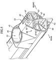
- Fig. 5 is a perspective view showing the attachment part 13 formed on the car beam end on the driver's (right) side.
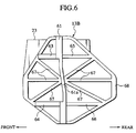
- Fig. 6 is a side view, also viewed from the right side of Fig. 5.
- the attachment part 13 is in the form of a honeycomb structure. That is, the attachment part 13 includes a plurality of later-mentioned ribs (61, 62, 63, 64, 65, 66, 67) formed in a recess opening outward in the vehicle-width direction. This recess is defined by a substantially-octagonal outer circumferential wall (surface) 68. Owing to the provision of the ribs 61 to 67, the interior of the recess is divided into a plurality of small spaces.
- an attachment wall (surface) 61 is formed so as to extend in the axial direction of the cross car beam 12 and also vertically. Further, the attachment wall 61 is also formed so as to project from the recess outwardly in the vehicle-width direction.
- Reinforcing ribs 63, 64 are formed to extend from upper and lower parts of the attachment wall 61 rearward of the vehicle, respectively. The reinforcing ribs 63, 64 are also formed so as to project from the recess.
- a plurality of fixing ribs 67 are formed so as to extend from a radial center (axis) 61a of the attachment wall 61 in the radial direction. Extending in the radial direction of the attachment part 13, these fixing ribs 67 are fixed to the inner face of the outer circumferential wall 68. Noted that respective leading ends of the ribs 61, 62, 63, 64, 65, 66 and 67 terminate at flat portions of the octagonal-shaped circumferential wall 68 respectively. Additionally, the attachment part 13 is joined, on its center side in the vehicle-width direction, to the blowout opening 45 outside the vent "blowout" port 23 thereby reinforcing it.
- the contour of the attachment part 13 is shaped to be substantially octagonal.
- the attachment part 13 may be shaped to be polygonal, circular and oval.
- the above ribs 63 to 67 are in the form of plate ribs.
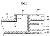
- the above attachment part 13 is a part of the second cylindrical body 30.
- the second cylindrical body 30 is made of high rigid resin and molded on the circumferential side of the first cylindrical body 28 by enveloped casing.
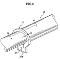
- Fig. 8 shows a modification of the attachment part for the supporting member.
- Fig. 8 is a perspective view of the cross car beam, showing an attachment part 26B just below the rib 25, in other words, under the axis of the cross car beam 12.
- a so-called brim-shaped rib 25 is formed over the whole periphery of the cross car beam 12 continuously and integrally.
- This rib 25 is shaped so as to have a small height H on the upper side of the cross car beam 12 and also the attachment part 26B on the lower side of the car beam 12.
- the attachment part 26B is provided with the bolt holes 27.
- the upper end of the support stay 16 is secured to the attachment part 26b with the engagement of bolts (not shown) with the bolt holes 27.
- the cylindrical body 28 is formed.
- the upper halved member 31 and the lower halved member 32 are made from different resins independently.
- the hollow cylindrical body 28 is completed.
- the lid member 29 and the second cylindrical body 30 of resins are molded on the circumferences of both ends of the first cylindrical body 28 respectively.
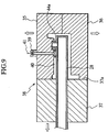
- the second cylindrical body 30 can be formed in enveloped casing by using a molding die 38 composed of a top die 35, a bottom die 36 and a side die 37, as shown in Fig. 9.
- a cavity 80 is defined between the first cylindrical body 28 and the inner surface of the molding die 38.
- molten resin 41 is poured into the cavity 40 through a gate 39 formed in the top die 35.
- the cavity 40 is filled up with the molten resin 41.
- the second cylindrical body 30 is formed on the circumference of the first cylindrical body 28 by enveloped casting.
- the cross car beam 12 of this embodiment is finished.
- the above molten resin has strength (in solid state) larger than that of the resin forming the first cylindrical body 28.
- molten resin mixed with fibers is preferable for the second cylindrical body 30.
- reference numeral 26C designates an attachment part as a modification of the attachment part 26B.
- the attachment parts 13, 13 of the cross car beam 12 which are required to have high rigidity in view of their attaching to the dash lower panel 14 of the vehicle body, are in the form of honeycomb structures, it is possible to fasten the cross car beam 12 to the vehicle body certainly. Further, in spite of the vent "blowout" port 23 as shown in Fig. 5, the strength in the vicinity of the opening 23 can be maintained by the above honeycomb structure.
- vent "blowout" port 23 is formed by the inner and outer openings 44, 45 in one body, the strength of the opening 23 is further improved.
- the first cylindrical body 28 is partially surrounded by the second cylindrical body 30 made from the molten resin 41 of high rigidity, it is possible to provide the cross car beam 12 with high rigidity. Therefore, even if the cross car beam 12 is provided, on its lower surface at the center side in the vehicle-width direction, with the opening 71 for connection with the previously-mentioned HVAC system, it is possible to maintain the strength of the cross car beam 12 as a whole.
- the car beam part on the driver's side that requires high rigidity in view of supporting the steering unit etc. is formed by a double-pipe structure of the first cylindrical body 28 and the second cylindrical body 30 in a tight manner. Additionally, the opening end of the second cylindrical body 30 outside the double-pipe structure is reinforced by the ribs 25 effectively. That is, owing to the provision of the ribs 25, it is possible to increase the coefficient of cross section of the second cylindrical body 30 at the opening end.
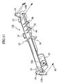
- Fig. 11 is a perspective view of a cross car beam 12B in accordance with the second embodiment of the present invention.
- the cross car beam 12B is provided, on both ends in the vehicle-width direction, with a pair of plate-shaped attachment flanges 13B, 13B extending outwardly in the vehicle-width direction.
- Each of the attachment flanges 13B, 13B has insertion holes 19 formed for insertion of bolts 43.
- a pair of steering support brackets (i.e. steering support parts) 20, 20 are formed on the outer circumferential face (rear-side) of the car beam 12B to support a steering wheel (not shown).
- the cross car beam 12B is further provided, on the front side, with an attachment bracket 21.
- Each of the steering support brackets 20, 20 has a tap-end stud bolt 49 formed to project downwardly by insert molding.
- the cross car beam 12B is provided, on the assistant driver's side, with an air-bag casing 22.
- a pair of cylindrical vent "blowout" ports 23, 24 are formed on the upper surface of the car beam 12B.
- a rib 25 is formed around the car beam 12B, for connection with a support stay (not shown).
- the rib 25 is provided, rearward and obliquely downwardly, with an attachment part 26 for fixation with the support stay.
- Fig. 12 is an exploded perspective view of the cross car beam 12B of second embodiment of the present invention.
- the cross car beam 12B includes a first cylindrical body 28 molded of resin previously, a lid member 29 arranged outside one end of the body 28B on the assistant driver's (left) side and also molded of resin by enveloped casting and a second cylindrical body 30 arranged outside one end of the cylindrical body 28 on the driver's (right) side and also molded of resin by enveloped casting.
- the first cylindrical body 28 has an upper halved member 31 having a substantial U-shaped section on the driver's (right) side and a lower halved member 32 having a substantial U-shaped section throughout.
- both ends thereof are closed by vertical walls 31a, 31a (only one shown in Fig. 12).
- both longitudinal ends of the lower halved member 32 are closed by vertical walls 32a, 32a respectively.
- the upper halved member 31 is provided, on both sides in the longitudinal direction, with a pair of openings 44, 24 forming the vent "blowout" ports 23 (Fig. 13), 24.
- the opening 44 on the driver's (right) side is surrounded by a flange 44a projecting upwardly.
- the opening 24 is surrounded by a flange 24a projecting upwardly.
- the air-bag casing 22 is formed on the rear surface of the lower halved member 32 integrally.
- an opening 22b is formed on the bottom of the casing 22, to accommodate a not-shown disk-shaped inflator for air-bag.
- the second cylindrical body 30 In the second cylindrical body 30, its end on the interior (assistant driver's) side in the vehicle-width direction is opened. Around this open end, the above rib 25 is formed so as to project outward in the radial direction of the cross car beam 12B. While, the second cylindrical body 30 is provided, at its outer end in the vehicle-width direction, with a plate-shaped attachment flange 13B extending vertically. Near the attachment flange 13B, a blowout opening 45 having a flange projecting upwardly is formed on the top of the second cylindrical body 30.
- the above-mentioned steering support brackets 20, 20 in pairs are formed on the rear surface of the second cylindrical body 30, in the form of bottomed boxes opening upwardly. While, the attachment bracket 21 is formed on the front surface of the second cylindrical body 30. These brackets 20, 20 and 21 are respectively formed integrally with the second cylindrical body 30. It is noted that the vent "blowout" port 23 of Fig. 13 has the blowout opening 44 of the first cylindrical body 28 and the blowout opening 45 of the second cylindrical body 30, providing a double-pipe structure in a tight manner.
- the steering support brackets 20, 20 are integrally formed on the circumferential surface of the second cylindrical body 30, there are integrally formed two steering support brackets 20, 20 projecting from the rear side of the body 30 backward of the vehicle and two steering support brackets 20, 20 projecting from the front side of the body 30 directing forward of the vehicle.
- the steering support brackets 20, 20 are arranged apart from each other in the vehicle-width direction, at a predetermined interval.
- each steering support bracket 20 includes a substantial U-shaped (or H-shaped) body part 50 extending from the outer circumferential surface 30a on the rear side of the body 30 rearward and a sidewall part 51 that closes an opening end of the body part 50 on the rear side of the vehicle.
- the body part 50 comprises a bottom part (plate) 50a arranged substantially horizontally and a pair of sidewalls 50b, 50b standing from both left and right ends of the bottom part 50a, providing a substantial U-shaped section.
- the bracket 20 is provided in the form of a substantial lid (or box) opening upward.
- a tap-end stud bolt (fastening member) 49 is formed so as to project downwardly by insert molding. The top of the stud bolt 49 is in a substantial plane with the bottom part 50a.
- the steering support bracket 20 may be arranged on the outer circumferential surface of the body 30 on the front side.
- a steering unit 53 can be attached to the steering support brackets 20 of the cross car beam 12B from its underside.
- the stud bolts 49 are arranged to extend from the steering support brackets 20, 20 downwardly.
- a flattened attachment surface 54 is formed in the upper part of the steering unit 53.
- the attachment surface 54 is provided, at comers thereof, with insertion holes 55 into which the stud bolts 49 are to be inserted.
- the steering unit 53 In assembling, it is firstly performed to lift up the steering unit 53 and successively insert the stud bolts 49 into the insertion holes 55. Subsequently, with thread-engagement of a nut 56 with each of the stud bolts 56, the steering unit 53 can be supported by the cross car beam 12B.
- the embodiment owing to the double-pipe structure of the first cylindrical body 28 and the second cylindrical body 30 in a tight manner, it is possible to reinforce the vicinities of the steering supporting part of the cross car beam 12B that requires high rigidity in view of supporting the steering unit 53 etc., effectively.
- the cross car beam 12B of this embodiment is subjected to a downward load through the steering brackets 20, 20.
- the downward load is dispersed to the attachment flanges 13B, 13B, the attachment bracket 21 and the attachment part 26 for the supporting stay uniformly.
- the enclosed casing area is relatively small in comparison with that of the second cylindrical body 30 since the rigidity required for the lid member 29 is smaller than that for the second cylindrical body 30.
- the air-bag casing 22 is formed in one body with the lower halved member 32, it is possible to reduce the number of components required for the installation of an air-bag unit.
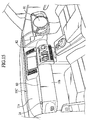
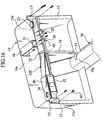
- Fig. 15 shows the front part of a vehicle cabin equipped with a cross car beam for a vehicle of this embodiment.
- an instrument panel 11 of this embodiment is arranged to extend from the driver's side to the assistant driver's side along a vehicle-width direction.
- This instrument panel 11 includes a front instrument panel 11a on the front side of the vehicle and a rear instrument panel 11b on the rear side of the vehicle.
- a decorative surface 80 of a later-mentioned cross car beam 12c is horizontally arranged on the assistant driver's side, between the front instrument panel 11a and the rear instrument panel 11b.
- This decorative surface 80 forms part of the surface of the instrument panel 11.
- a steering unit 81 is arranged on the driver's side, while a switch panel 82 is arranged at the intermediate part in the vehicle-width direction.
- the cross car beam 12C is arranged so as to extend from the driver's side to the assistant driver's side in the vehicle-width direction.
- the cross car beam 12C is provided, on both right and left sides thereof, with attachment flanges 13, 13.
- the dash lower panel 14 is arranged in front of the cross car beam 12C.
- the dash floor panel 14 is provided, on both sides thereof in the vehicle-width direction, with the side panel parts 15a, 15a each having the attachment flanges 15, 15 folded to extend from respective rear edges of the side panels 15a, 15a to an cut-vehicle direction.
- the above attachment flanges 13, 13 of the cross car beam 12C are fastened to the attachment flanges 15, 15 by means of the bolts 43. Additionally, the cross car beam 12C is supported, on its center side, by the upper surface 18a of the tunnel part 18 of a floor panel through the support stay 16 and the attachment bracket 17. On the driver's side of the vehicle (e.g. the right-hand side of Fig. 2), the attachment bracket 21 is fixed to the front-side of the cross car beam 12C. The attachment bracket 21 is attached to the rear face 14a of the dash lower panel 14 through the support bracket 48 having U-shaped section in side view.
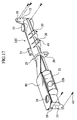
- Fig. 17 is a perspective view of the cross car beam 12C of this embodiment.
- the cross car beam 12C is provided, on both ends in the vehicle-width direction, with the plate-shaped attachment flanges 13, 13 extending outwardly in the vehicle-width direction.
- Each of the attachment flanges 13, 13 has insertion holes 19 formed for insertion of the bolts 43.
- the cross car beam 12C is provide, on the driver's side, with the steering support brackets (i.e. steering support parts) 20, 20 for supporting the steering unit 81 (see Fig. 15) on the outer circumferential face (rear-side) of the beam 12C.
- the cross car beam 12C is further provided, on the front side, with the attachment bracket 21 for fixing the cross car beam 12C to the dash lower panel 14.
- Each of the steering support brackets 20, 20 has a tap-end stud bolt 49 formed to project downwardly by insert molding.
- the cross car beam 12C is provided, on its rear face on the assistant driver's side, with the air-bag casing 22.
- the cylindrical vent "blowout" ports 23, 24 are formed on the upper surface of the beam 12C. Noted that, in the rib 25 of the cross car beam 12C on the driver's side, an attachment part 26 for attachment to a supporting member is formed to extend from the main body of the beam 12C rearward and obliquely downwardly.
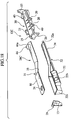
- Fig. 18 is an exploded perspective view of the cross car beam 12C of third embodiment of the present invention.
- the cross car beam 12C includes a first cylindrical body 28C molded of resin previously, the lid member 29 arranged outside one end of the body 28C on the assistant driver's (left) side and also molded of resin by enveloped casting and the cylindrical reinforcing body 30 (i.e. the second cylindrical body) arranged outside one end of the cylindrical body 28C on the driver's (right) side and also molded of resin by enveloped casting.
- the cylindrical body 28C has an upper halved member 31 having a substantial U-shaped section on the driver's (right) side and a lower halved member 32 having a substantial U-shaped section throughout.
- the upper halved member 31 On the driver's side, the upper halved member 31 has an end closed by a vertical wall 32a. While, both longitudinal ends of the lower halved member 32 are closed by vertical walls 32a, 32a respectively.
- the upper halved member 31 is provided, on both sides in the longitudinal direction, with vent “blowout” openings 44, 24.
- the opening 44 on the driver's (right) side is surrounded by a flange 44a projecting upwardly.
- the above-mentioned air-bag casing 22 is formed in one body with the member 32, in the form of a bottomed box.
- an opening 22b is formed to accommodate a not-shown disk-shaped inflator for air-bag.
- the cylindrical reinforcing body 30 is provided, inside in the vehicle-width direction, with an opened end around which the rib 25 is formed over the whole circumference so as to project radially outward of the cross car beam 12C. While, the cylindrical reinforcing body 30 is provided, at its outer end in the vehicle-width direction, with the plate-shaped attachment flange 13 extending vertically. Near the attachment flange 13 and on the top of the cylindrical reinforcing body 30, a blowout opening 45 is provided with a flange projecting upwardly. On the rear surface of the reinforcing body's part (30) in the vicinity of the opening 45, the above steering support brackets 20, 20 in pairs are arranged in the form of bottomed boxes opening upwardly.
- the attachment bracket 21 is formed on the front surface of the reinforcing body's part (30) in the vicinity of the opening 45.
- These brackets 20, 20 and 21 are respectively formed integrally with the cylindrical reinforcing body 30.
- the vent "blowout" port 23 of Fig. 17 has the blowout opening 44 of the cylindrical body 28C and the blowout opening 45 of the cylindrical reinforcing body 45, providing a double-pipe structure fitted tightly.
- Fig. 19 is a perspective view of the cylindrical body 28C.
- Fig. 20 is a front view of the cylindrical body 28C.
- a parting line L between the upper halved member 31 and the lower halved member 32 is positioned at the center in the vertical direction of the vehicle on a driver's (right) side 83, slanted obliquely upward in an intermediate part 84 in the vehicle-width direction and further arranged along a top end 22a of the casing 22 substantially horizontally on an assistant driver's (left) side 85.
- an upper surface 31a of the upper halved member 31 is also formed substantially horizontally on the driver's side 83, gradually slanted obliquely upward in the intermediate part 84 in the vehicle-width direction and also formed substantially horizontally on the assistant driver's side 85 to provide the above decorative surface 80. That is, as shown in Fig. 20, since the parting line L on the assistant driver's side is arranged along the decorative surface 80 as being the upper surface 31a of the upper halved member 31, it has a substantially constant thickness D along the vehicle-width direction,
- an attachment surface 86 of the air-bag casing 22 is inclined so as to rise upward as directing the front of the vehicle.
- the thickness D of the upper halved member 31 is generally constant on the assistant driver's side 85, the flow of molten resin is uniformized during the molding of the halved member 31, whereby it is possible to form the decorative surface 80 smoothly.
- an air bag (not shown) is activated to expand in a short time.
- a passenger is forced on the air bag.
- a load F is applied to the attachment surface 86 substantially perpendicularly.
- the air-bag casing 22 itself is formed integrally with the halved member 32, it is possible to provide the casing 22 with a designated strength in spite of its thinness.
- the air-bag casing 22 is formed in one body with the lower halved member 32. Accordingly, the rigidity of the air-bag casing 22 can be improved furthermore.
- the cylindrical body 28C is formed.
- the upper halved member 31 and the lower halved member 32 are made from different resins independently.
- the hollow cylindrical body 28C is completed.
- the lid member 29 and the cylindrical reinforcing body 30 of resins are molded on the circumferences of both ends of the cylindrical body 28C respectively.
- a cavity therein is supplied and filled up with molten resin.
- the cylindrical reinforcing body 30 is formed on the circumference of the cylindrical body 28C by enveloped casting.
- the above molten resin has strength (in solid state) larger than that of the resin forming the cylindrical body 28C.
- molten resin mixed with fibers is preferable for the cylindrical reinforcing body 30.
- its part on the driver's side that is required to have high rigidity in view of supporting a steering etc. is formed by both of the cylindrical body 28C and the cylindrical reinforcing body 30 in tight junction, providing a double-pipe structure.
Landscapes
- Engineering & Computer Science (AREA)
- Chemical & Material Sciences (AREA)
- Combustion & Propulsion (AREA)
- Transportation (AREA)
- Mechanical Engineering (AREA)
- Body Structure For Vehicles (AREA)
Abstract
Description
- The present invention relates to a cross car beam for a vehicle.
- Generally, the cross car beam is arranged inside an automotive instrument panel while fixing both car beam's ends in the vehicle-width direction to pillar members on both lateral sides of a vehicle body or a dash panel. In this state, the cross car beam performs a role to support a steering unit, the instrument panel and so on. Therefore, in view of ensuring beam's rigidity meeting such a role, the cross car beam is generally made from high rigid materials, such as steels and manganese.
- Japanese Patent Application Laid-open No. 2002-211441 discloses a cross car beam made of synthetic resin. In the above art, the disclosed cross car beam is provided, on its attachment surfaces to the vehicle body, with additional ribs. Alternatively, the attachment surfaces are increased in thickness. In this way, the attachment surfaces are reinforced to increase the strength of the cross car beam.
- However, in case of the former cross car beam of steels or the like, it should be noted that the total weight of the cross car beam is increased disadvantageously. While, in case of the latter cross car beam made of synthetic resin, the usage amount of synthetic resin is increased due to the provision of the thickened ribs or additional ribs, causing the beam's material cost in manufacturing to be raised.
- Additionally, if a cross car beam is provided, on both sides thereof, with "vent" blowout ports, there arises a possibility that the cross car beam is weakened in strength of beam's portions in the vicinity of the blowout ports.
- It is generally noted that the cross car beam has its intermediate part (in the vehicle-width direction) supported by a floor panel etc. on the side of the vehicle body through the intermediary of a support stay. As mentioned before, in view of the requirements to support the instrument panel and the steering unit, it is necessary to provide a cross car beam with high rigidity. For this purpose, such a cross car beam is provided with a high rigid attachment part for fixation with a support member on the side of the vehicle body. This attachment part is formed by high rigid material, such as steel and manganese. In assembling, the attachment part of the cross car beam is fixed to an end of the support stay (as the above support member), while the other end of the support stay is fixed to a floor panel of the vehicle body. In this way, the cross car beam is carried by the vehicle body (see Japanese Patent Application Laid-open No. 2002-284018).
- However, it should be noted that a supporting structure for a cross car beam in accordance with the above prior art has various problems to be solved. First, in case of an attachment pan of steel, the weight of the cross car beam is increased. Secondly, in case of an attachment part of manganese, the manufacturing cost of the cross car beam is also elevated.
- To the contrary, when a cross car beam and its attachment part are formed by resinous materials, there arises a possibility that the supporting rigidity of the cross car beam is lowered in comparison with that of the cross car beam made of steel, manganese or the like.
- Additionally, in view that the cross car beam has a role to carry a steering unit etc., an air conditioning unit for feeding warm or cool wind into a vehicle cabin is arranged independently of such a cross car beam (see Japanese Patent Application Laid-open No. 2001-328421).
- Meanwhile, Japanese Patent Application Laid-open No. 2002-284018 discloses a cross car beam that is equipped, on its peripheral surface, with steering support brackets for supporting a steering unit. In manufacturing, after forming a main body for the cross car beam, attachment bolts for supporting the steering unit are attached to the steering support brackets of the cross car beam.
- Thus, the steering support brackets support the steering unit through the attachment bolts. As the steering unit is generally heavy, it is necessary for the steering support brackets to have great mechanical strength.
- However, as the above-mentioned steering support bracket are thickened in view of ensuring high rigidity corresponding to the required mechanical strength, the cost of components of the cross car beam is apt to rise disadvantageously.
- Additionally, it is noted that the above prior art (Japanese Patent Application Laid-open No. 2002-284018) requires to fit the attachment bolts to the steering support brackets after providing the cross car beam with the steering support. It means that the manufacturing of the cross car beam of the prior art has a tendency of wasting time and labor.
- As mentioned previously, the cross car beam is arranged inside the instrument panel generally. In connection, the cross car beam is generally provided, on the assistant driver's side, with an air-bag attachment member for installation of an air-bag unit. This air-bag attachment member has to be provided with a designated strength because it may be subjected, at a vehicle collision, to a collision impact transmitted from a passenger through an air bag. As mentioned before, since the cross car beam is adapted to support an instrument panel and a steering unit, the cross car beam and the air-bag attachment member are formed by the use of high rigid materials, such as steels (see Japanese Patent Application Laid-open No. 10-119684).
- However, in this case, it should be noted that the total weight of the cross car beam is increased disadvantageously.
- While, in case of forming a cross car beam and an air-bag attachment member cross by the use of synthetic resin lighter in weight than steel, it is necessary to thicken the cross car beam and the air-bag attachment member in view of their rigidity, thereby causing material cost in manufacturing to be raised.
- In the above-mentioned situations, it is an object of the present invention to provide a cross car beam for a vehicle, which can improve both attaching rigidity and supporting rigidity about the cross car beam without rises in weight and material cost.
- Further, it is another object of the present invention to provide a cross car beam with a steering supporting structure, which can save the manufacturing cost and simplify the forming operation.
- Still further, it is a further object of the present invention to provide a cross car beam for a vehicle, which can improve the rigidity of the car beam, especially, an air-bag attachment member without rises in weight and material cost.
- In order to attain the above objects, a cross car beam of the present invention comprises: a first cylindrical body arranged along a vehicle-width direction so as to extend from a driver's side to an assistant driver's side; a second cylindrical body arranged on the outer circumference of a first cylindrical body's part on the driver's side and wound around the first cylindrical body in a tight manner, thereby providing the cross car beam with a double-pipe structure of the first cylindrical body and the second cylindrical body.
- According to the present invention of the above constitution, it is possible to improve both attaching rigidity and supporting rigidity about the cross car beam without rises in weight and material cost.
- Preferably, at least either one of an end of the first cylindrical body on an assistant driver's side thereof and an end of the second cylindrical body on a driver's side thereof is provided with an attachment part which is formed to be fixable to a constituent member of a vehicle body, the attachment part having a honeycomb structure.
- According to the above constitution, since the attachment part is formed to be a honeycomb structure, it is possible to improve the mechanical strength of the attachment part without rises in weight and material cost. Consequently, even if the cross car beam is made of synthetic resin, it is possible to attach the cross car beam to a constituent of the vehicle body certainly.
- The honeycomb structure has a plurality of plate ribs formed so as to extend from an axis of the first cylindrical body or an axis of the second cylindrical body radially.
- According to the above constitution, since the attachment part is provided in the form of a honeycomb structure of the plate ribs, it is possible to disperse a torsion torque inputted to the cross car beam into the plate ribs effectively and also possible to transmit the torsion torque to the vehicle body effectively.
- The first cylindrical body and the second cylindrical body may be respectively provided, on their circumferential surfaces close to the attachment part, with vent blowout ports that communicate with the interior of the first cylindrical body and the interior of the second cylindrical body, respectively.
- According to the above constitution, since the rigidity of the attachment part of the cross car beam is improved, it is possible to suppress the reduction in strength of the vicinity of the attachment part due to the formation of the vent blowout ports.
- Further, the cross car beam may further comprises a steering supporting part arranged in the vicinity of the attachment part to support a steering unit of the vehicle.
- According to the above constitution, since the rigidity of the attachment part of the cross car beam is improved, it is possible to improve the rigidity of the steering supporting part formed near the attachment part of the cross car beam. Accordingly, the cross car beam is capable of supporting the steering unit certainly in spite of vibrations during a vehicle's traveling.
- Preferably, the cross car beam further comprises a rind member adapted so as to envelop the outer periphery of the end of the first cylindrical member on the assistant driver's side, wherein the attachment part is arranged on an end of the rind member and the second cylindrical member is provided, on the end on the driver's side, with another attachment part.
- Then, it is possible to shorten the inside cylindrical member as the hollow first cylindrical body thereby suppressing a reduction in rigidity of the cross car beam as a whole and also possible to provide the attachment part with high rigidity owing to the provision of the rind member and the second cylindrical member.
- Alternatively, the cross car beam may further comprise a support member, wherein the second cylindrical body is provided, on a periphery thereof, with a rib having an attachment part for the support member, and the support member has one end attached to the attachment part and the other end fixed to a constituent member of a vehicle body, whereby an intermediate part of the cross car beam in a vehicle-width direction is supported by the constituent member through the support member.
- According to the above constitution, since the rib is provided with the attachment part for the support member, it is possible to improve the mechanical strength of the above attachment part without rises in weight and material cost about the cross car beam. Consequently, even if the cross car beam is made of synthetic resin, it can be supported by a constituent of the vehicle body certainly.
- In the modification, the rib may be formed on an inside end of the second cylindrical body in a vehicle-width direction.
- In this case, owing to the formation of the rib on the inside end of the second cylindrical body in the vehicle-width direction, it is possible to improve the strength of the opened end of the second cylindrical body remarkably. Consequently, it is possible to provide the car beam part on the driver's side where rigidity is required, with a double-pipe structure having of the first cylindrical body and the second cylindrical body thereby improving the rigidity of the whole cross car beam and also possible to suppress a reduction in strength of the cross car beam caused by the opening of the second cylindrical body.
- In the cross car beam, the attachment part for the supporting member may be arranged, in the rib, on the lower side of the second cylindrical body.
- According to the above structure, since the supporting member supports the lower side of the cross car beam, the weight of the cross car beam is transmitted to the supporting member effectively, whereby the cross car beam can be held by the vehicle body certainly.
- Alternatively, the first cylindrical body may be provided, on its intermediate part in a vehicle-width direction, with an opening for connection with an air conditioning unit.
- Then, since the opening for connection with the air conditioning unit is formed on the center side of the first cylindrical body in the vehicle-width direction, it is possible to utilize part of the cross car beam as an air duct through which warm and cool air from the air conditioning unit is blown into the vehicle cabin.
- Further, the first cylindrical body may be provided, on a driver's side thereof, with a steering supporting part to support a steering unit of the vehicle and furthermore, the first cylindrical body's part close to a steering supporting part may be formed to provide the double-pipe structure together with the second cylindrical body.
- Then, owing to the provision of the double-pipe structure in the vicinity of the steering supporting part, the same structure allows the heavy steering unit to be supported stably.
- Alternatively, the first cylindrical body and the second cylindrical body may be respectively made of synthetic resin. In connection, the strength of synthetic resin forming the second cylindrical body is established larger than that of synthetic resin forming the first cylindrical body.
- With the above establishment in strength between the first cylindrical body and the second cylindrical body, it is possible to remarkably improve the strength of a car beam part on the driver's side, especially, the vicinities of the steering supporting part while accomplishing to lighten the whole cross car beam.
- Further, the first cylindrical body may be formed by an upper halved member on the upside of the vehicle and a lower halved member on the downside of the vehicle, both of which are welded to each other.
- According to the above structure, since the first cylindrical body is formed by both of the upper halved member and the lower halved member, the constitution allows a load applied on the cross car beam to be received and caught effectively. Generally noted that the cross car beam carries a steering unit, an instrument panel, etc., so that an external force (load) therefrom acts downwardly of the vehicle. However, since the first cylindrical body of the car beam is formed by the upper and lower halved members each having respective welding surfaces arranged generally horizontally, the strength of the cross car beam against the external force is remarkably increased at the above welding surfaces.
- In the cross car beam, the second cylindrical body may be provided with a steering support member projecting in a fore-and-aft direction of the vehicle and furthermore, the steering support member may be formed by a plate extending from the periphery of the second cylindrical body in the fore-and-aft direction of the vehicle and a sidewall part formed around the plate.
- According to the above constitution, it is possible to improve the mechanical strength of the cross car beam against a load, especially, load in the vertical direction of the vehicle. As a result, it is possible to allow the cross car beam to carry a heavy steering unit certainly without rising the material cost for the car beam substantially. When forming the cross car beam by injection molding, the integral arrangement of the steering support member with the cross car beam could improve the attaching strength of the steering support member. In this case, with a simple constitution of an upper molding die and a lower molding die for injection molding, it becomes possible to form the above-constructed steering support member.
- In the above cross car beam, a steering unit may be supported on the lower surface of the steering support member, wherein the double-pipe structure's part in the vicinity of the steering support member has a vent blowout port formed in a manner that its upper part opens, thereby blowing out wind against a vehicle cabin.
- According to the above constitution, the rigidity of the cross car beam itself is improved by the steering support member. Therefore, despite that the vent blowout port is formed in the cross car beam, it is possible for the cross car beam to maintain its strength against vertical vibrations through the steering unit because the blowout port is not positioned in a vertical wall of the car beam but in its upper surface opposite to the lower surface to carry the steering unit.
- In the above-mentioned structure, the steering support member may be arranged on the peripheral surface of the second cylindrical body, on each of the front and rear sides of the vehicle.
- According to the above arrangement, owing to the formation of the steering support members on both front and rear sides of the cross car beam, it can support the steering unit uniformly.
- Alternatively, in the cross car beam, the steering support member may have a fastening member molded in one body therewith to project downwardly, and the steering unit is attached to the fastening member, thereby supporting the steering unit through the steering support member.
- Then, owing to the integral formation of the steering support member with the fastening member, there is no need to establish an additional process to attach the fastening member to the steering support member, whereby the forming operation of the cross car beam can be simplified.
- In the cross car beam of the present invention, the first cylindrical body may be formed by halved members and further, one of the halved members may be provided with an air-bag attachment member.
- Additionally, in the above modification, it is preferable that the first cylindrical body may be formed so that its upper surface on an assistant driver's side becomes higher than the upper surface on a driver's side, the first cylindrical body is formed by an upper halved member on the upside of the vehicle and a lower halved member on the downside of the vehicle, both of which are welded to each other, the air-bag attachment member is provided on the assistant driver's side of the lower halved member and that a parting line between the upper halved member and the lower halved member is arranged, on the driver's side, at the central part of the first cylindrical body in a vertical direction of the vehicle and also arranged, on the assistant driver's side, above the air-bag attachment member.
- According to the above constitution, since the parting line on the assistant driver's side is arranged above the air-bag attachment member, it is possible to form the air-bag attachment member itself in one body, whereby its strength can be improved. Consequently, it is possible to provide the first cylindrical body with enough rigidity to cope with an external load that might be inputted to the air-bag attachment member through an air bag at a vehicle collision.
- Further, the parting line on the assistant driver's side may be arranged along the upper surface of the first cylindrical body.
- Then, due to the above arrangement of the parting line, it is possible to make a thickness of the upper halved member generally constant. Therefore, when forming the halved members by injection molding of molten resin, it becomes possible to make the flowing of molten resin smooth in the upper halved member, thereby avoiding an occurrence of molding defects, such as shrinkage and cavity.
- Alternatively, the upper surface of the first cylindrical body on the assistant driver's side may form a part of a surface of an instrument panel.
- According to the above constitution, it is possible to constitute the upper surface of the upper halved member, which is excellent in terms of molding quality, as part of the surface of the instrument panel. Consequently, it is possible to lighten the instrument panel with a reduction of material cost.
- These and other objects and features of the present invention will become more fully apparent from the following description and appended claims taken in conjunction with the accompany drawings.
-
- Fig. 1 is a perspective view of a front part of a vehicle body where a cross car beam of the first embodiment of the present invention is arranged;
- Fig. 2 is a respective view showing the mount arrangement of the cross car beam where an instrument panel of Fig. 1 is detached;
- Fig. 3 is a perspective view showing the whole cross car beam of the embodiment in accordance with the first embodiment of the invention.
- Fig. 4 is an exploded perspective view of the cross car beam in accordance with the first embodiment of the invention;
- Fig. 5 is a perspective view of the cross car beam of the first embodiment, showing its attachment of the driver's seat side;
- Fig. 6 is a side view of the attachment of Fig. 5, viewed from the right-hand side;
- Fig. 7 is a sectional view taken along a line 7-7 of Fig. 5;
- Fig. 8 is an enlarged perspective view of the essential part of Fig. 3, showing a modification of the attachment for a holder member;
- Fig. 9 is a sectional view of a molding die for molding the cross car beam of the first embodiment;
- Fig. 10 is a perspective view showing a parting line of the cross car beam of the first embodiment;
- Fig. 11 is a perspective view of the whole cross car beam in accordance with the second embodiment of the present invention;
- Fig. 12 is an enlarged perspective view of the cross car beam of the second embodiment;
- Fig. 13 is a perspective view of the cross car beam provided, on both front and rear sides of a vehicle, with brackets for supporting a steering;
- Fig. 14 is a perspective view showing a state to attach a steering unit to the cross car beam of the second embodiment;
- Fig. 15 is a perspective view of the front part of a vehicle body where a cross car beam in accordance with the third embodiment of the present invention;
- Fig. 16 is a respective view showing the mount arrangement of the cross car beam where an instrument panel of Fig. 15 is detached;
- Fig. 17 is a perspective view showing the whole cross car beam of the third embodiment;
- Fig. 18 is an exploded perspective view of the cross car beam of the third embodiment;
- Fig. 19 is a perspective view of a cylindrical body forming the cross car beam of the third embodiment;
- Fig. 20 is a sectional view showing a parting line of the cylindrical body of the third embodiment; and
- Fig. 21 is a sectional view taken along a line 21-21 of Fig. 19.
-
- Referring to accompanying drawings, various embodiments of the present invention will be described below.
- Fig. 1 shows the interior of a vehicle cabin of a
vehicle body 10 on the application of a cross car beam of the first embodiment of the invention. - On the front side of the vehicle cabin, there is arranged an
instrument panel 11. Inside theinstrument panel 11, in other words, on the front side of thepanel 11, across car beam 12 is arranged so as to extend from the driver's side (or driver's seat side) to the assistant driver's side (or assistant driver's seat side) of a vehicle. - As shown in Fig. 2, the
cross car beam 12 is provided, on both right and left sides thereof, withattachment parts lower panel 14 is arranged in front of thecross car beam 12. Thedash floor panel 14 is provided, on both sides thereof in a vehicle-width direction, withside panel parts attachment flanges panels above attachment parts cross car beam 12 are fastened to theattachment flanges bolts 43. Additionally, thecross car beam 12 is supported, on its center side, by anupper surface 18a of atunnel part 18 of a floor panel through asupport stay 16 and a L-shapedattachment bracket 17. - On the driver's side of the vehicle (e.g. the right-hand side of Fig. 2), an
attachment bracket 21 is fixed to the outer circumferential face (front-side) of thecross car beam 12. Theattachment bracket 21 is attached to arear face 14a of the dashlower panel 14 through asupport bracket 48 having U-shaped section in side view. - Fig. 3 is a perspective view of the
cross car beam 12 of this embodiment. Thecross car beam 12 is provide, on the driver's side, with steering support brackets (i.e. steering support parts) 20, 20 for supporting the steering unit on the outer circumferential face (rear-side) of thebeam 12. As mentioned above, thecross car beam 12 is provided, on the front side, with theattachment bracket 21 for fixing thecross car beam 12 to the dashlower panel 14. Each of thesteering support brackets end stud bolt 49 formed to project downwardly by insert molding. On the other hand, thecross car beam 12 is provide, on its rear face on the driver's side, with an air-bag casing 22. On both right and left ends of thecross car beam 12, cylindrical vent "blowout"ports beam 12. Thecross car beam 12 has arib 25 formed in the vicinity of the beam's center in the vehicle-width direction and also on the driver's side, for connection with thesupport stay 16. In the lower portion of therib 25, anattachment part 26 is provided for its attachment with thesupport stay 26. Further bolt holes are formed in theattachment part 26, for engagement with thesupport stay 16. In assembly, the upper end of thesupport stay 16 is fastened to the bolt holes 17 by means of bolts. - Fig. 4 is an exploded perspective view of the
cross car beam 12 of the embodiment. - The
cross car beam 12 includes a firstcylindrical body 28 made of resin and molded previously, alid member 29 made of resin and molded outside one end of thebody 28 on the assistant driver's side by enveloped casting and a secondcylindrical body 30 made of resin and molded outside one end of thebody 28 on the driver's side by enveloped casting. - The
cylindrical body 28 has an upper halvedmember 31 having a substantial U-shaped section and a lowerhalved member 32 having a substantial U-shaped section throughout. The halvedmembers vertical walls member 31 is provided, on both sides in the longitudinal direction, withopenings ports openings flanges member 32 is provided, at its intermediate part in the vehicle-width direction, with alower opening 71, which is connected to a not-shown HVAC (Heating, Ventilating and Air-Conditioning) system. Theopening 71 is surrounded by aflange 72 extending downwardly. On the rear surface of the lowerhalved member 32, the above-mentioned air-bag casing 22 is formed in one body with themember 32, in the form of a bottomed box. On the bottom of thecasing 22, anopening 22b is formed to accommodate a not-shown disk-shaped inflator for air-bag. - On the other hand, the
cylindrical body 30 is provided, inside in the vehicle-width direction, with an opened end around which therib 25 is formed over the whole circumference so as to project radially outward of thecross car beam 12. On the underside of therib 25, theattachment part 26 is formed so as to project downwardly. In assembling, thesupport stay 16 is fastened to theattachment part 26 of therib 25. The secondcylindrical body 30 is provided, at its outer end in the vehicle-width direction, with theattachment part 13 extending vertically. Near theattachment part 13 and on the top of the secondcylindrical body 30, ablowout opening 45 is provided with a flange projecting upwardly. On the rear surface of the cylindrical body's part (30) in the vicinity of theopening 45, the abovesteering support brackets attachment bracket 21 is formed on the front surface of the cylindrical body's part (30) in the vicinity of theopening 45. Thesebrackets cylindrical body 30. It is noted that the vent "blowout"port 23 of Fig. 3 has the blowout opening 44 of the firstcylindrical body 28 and the blowout opening 45 of the secondcylindrical body 30, providing a double-pipe structure in a tight manner. - As mentioned before, the
cross car beam 12 is provided, on both (left and right) sides thereof, with theattachment parts attachment part 13 formed on the car beam end on the driver's (right) side. Fig. 6 is a side view, also viewed from the right side of Fig. 5. - As shown in these figures, the
attachment part 13 is in the form of a honeycomb structure. That is, theattachment part 13 includes a plurality of later-mentioned ribs (61, 62, 63, 64, 65, 66, 67) formed in a recess opening outward in the vehicle-width direction. This recess is defined by a substantially-octagonal outer circumferential wall (surface) 68. Owing to the provision of theribs 61 to 67, the interior of the recess is divided into a plurality of small spaces. In detail, at the center of theattachment part 13 in the fore-and-aft direction of the vehicle, an attachment wall (surface) 61 is formed so as to extend in the axial direction of thecross car beam 12 and also vertically. Further, theattachment wall 61 is also formed so as to project from the recess outwardly in the vehicle-width direction. Reinforcingribs attachment wall 61 rearward of the vehicle, respectively. The reinforcingribs ribs circumferential wall 68. In the recess part preceding theattachment wall 61,support ribs wall 61 forwardly in level with the reinforcingribs wall 61 to allow it to overlap with the attachment flange 15 (Fig 2). In theattachment wall 61, its parts equipped with the bolt holes 62 are large in thickness, while the intermediate part between the reinforcingribs - In the above recess, as shown in Fig. 6, a plurality of fixing
ribs 67 are formed so as to extend from a radial center (axis) 61a of theattachment wall 61 in the radial direction. Extending in the radial direction of theattachment part 13, these fixingribs 67 are fixed to the inner face of the outercircumferential wall 68. Noted that respective leading ends of theribs circumferential wall 68 respectively. Additionally, theattachment part 13 is joined, on its center side in the vehicle-width direction, to theblowout opening 45 outside the vent "blowout"port 23 thereby reinforcing it. - In the shown embodiment of Fig. 6, the contour of the
attachment part 13 is shaped to be substantially octagonal. However, unlimitedly to this embodiment, theattachment part 13 may be shaped to be polygonal, circular and oval. Theabove ribs 63 to 67 are in the form of plate ribs. - As shown in Fig. 7, which is, a sectional view taken along a line 7-7 of Fig. 5, the
above attachment part 13 is a part of the secondcylindrical body 30. The secondcylindrical body 30 is made of high rigid resin and molded on the circumferential side of the firstcylindrical body 28 by enveloped casing. - Fig. 8 shows a modification of the attachment part for the supporting member. Fig. 8 is a perspective view of the cross car beam, showing an
attachment part 26B just below therib 25, in other words, under the axis of thecross car beam 12. As shown in the figure, in the vicinity of the center part of thecross car beam 12 in the vehicle-width direction, a so-called brim-shapedrib 25 is formed over the whole periphery of thecross car beam 12 continuously and integrally. Thisrib 25 is shaped so as to have a small height H on the upper side of thecross car beam 12 and also theattachment part 26B on the lower side of thecar beam 12. Theattachment part 26B is provided with the bolt holes 27. In assembly, the upper end of thesupport stay 16 is secured to the attachment part 26b with the engagement of bolts (not shown) with the bolt holes 27. - The forming method of the
cross car beam 12 will be described in brief. - First of all, it is performed to mold the
cylindrical body 28. Previously, by injection molding, the upper halvedmember 31 and the lower halved member 32 (see Fig. 4) are made from different resins independently. Thereafter, by weldingrespective peripheries members cylindrical body 28 is completed. - Next, by enveloped casing, the
lid member 29 and the secondcylindrical body 30 of resins are molded on the circumferences of both ends of the firstcylindrical body 28 respectively. The secondcylindrical body 30 can be formed in enveloped casing by using a molding die 38 composed of atop die 35, abottom die 36 and a side die 37, as shown in Fig. 9. - Upon positioning the previously-formed first
cylindrical body 28 in the molding die 38, when moving the top die 35, the bottom die 36 and the side die 37 to complete the molding die 38, acavity 80 is defined between the firstcylindrical body 28 and the inner surface of the molding die 38. Then,molten resin 41 is poured into thecavity 40 through agate 39 formed in the top die 35. Subsequently, thecavity 40 is filled up with themolten resin 41. From this state, as themolten resin 41 hardens in thecavity 40, the secondcylindrical body 30 is formed on the circumference of the firstcylindrical body 28 by enveloped casting. Thereafter, when the top die 35, the bottom die 36 and the side die 37 are moved to open the molding die 38, thecross car beam 12 of this embodiment is finished. Here, it is desirable that the above molten resin has strength (in solid state) larger than that of the resin forming the firstcylindrical body 28. For example, molten resin mixed with fibers is preferable for the secondcylindrical body 30. - Further, the molding die 38 is opened by moving the top die 35 and the bottom die 36 up and down on the boundary of a substantially-
horizontal parting line 42 respectively, as shown with arrow of Fig. 10. Noted thatreference numeral 26C designates an attachment part as a modification of theattachment part 26B. - According to the attachment structure of the cross car beam of this embodiment, since the
attachment parts cross car beam 12, which are required to have high rigidity in view of their attaching to the dashlower panel 14 of the vehicle body, are in the form of honeycomb structures, it is possible to fasten thecross car beam 12 to the vehicle body certainly. Further, in spite of the vent "blowout"port 23 as shown in Fig. 5, the strength in the vicinity of theopening 23 can be maintained by the above honeycomb structure. - Hitherto, there is defined a dead space between the vent "blowout"
port 23 and the attachment wall (surface) 61. According to the embodiment, it is possible to make effective use of the above space for theattachment part 13 of high rigidity resulting from the honeycomb structure. Again, owing to the honeycomb structure including a plurality of ribs, it is possible to transmit a torsion torque inputted to thecross car beam 12 to the vehicle body while effectively dispersing the torque to theribs 63 to 67 (see Fig. 6). - Noted that since the vent "blowout"
port 23 is formed by the inner andouter openings opening 23 is further improved. - Since the first
cylindrical body 28 is partially surrounded by the secondcylindrical body 30 made from themolten resin 41 of high rigidity, it is possible to provide thecross car beam 12 with high rigidity. Therefore, even if thecross car beam 12 is provided, on its lower surface at the center side in the vehicle-width direction, with theopening 71 for connection with the previously-mentioned HVAC system, it is possible to maintain the strength of thecross car beam 12 as a whole. - According to the support structure of the cross car beam of the embodiment, the car beam part on the driver's side that requires high rigidity in view of supporting the steering unit etc. is formed by a double-pipe structure of the first
cylindrical body 28 and the secondcylindrical body 30 in a tight manner. Additionally, the opening end of the secondcylindrical body 30 outside the double-pipe structure is reinforced by theribs 25 effectively. That is, owing to the provision of theribs 25, it is possible to increase the coefficient of cross section of the secondcylindrical body 30 at the opening end. - As shown in Fig. 9, since the side die 37 is provided, at its part corresponding to the
attachment part 26 of therib 25, with no draft angle, the opening end of the secondcylindrical body 30 becomes parallel with aside surface 37a of the side die 37. Consequently, the fastening strength of theattachment part 26 with the support stay 16 can be improved. - The second embodiment of the present invention will be described with reference to the drawings.
- Fig. 11 is a perspective view of a
cross car beam 12B in accordance with the second embodiment of the present invention. As mentioned above, thecross car beam 12B is provided, on both ends in the vehicle-width direction, with a pair of plate-shapedattachment flanges attachment flanges bolts 43. On the driver's side of thecross car beam 12B, a pair of steering support brackets (i.e. steering support parts) 20, 20 are formed on the outer circumferential face (rear-side) of thecar beam 12B to support a steering wheel (not shown). On the other hand, thecross car beam 12B is further provided, on the front side, with anattachment bracket 21. - Each of the
steering support brackets end stud bolt 49 formed to project downwardly by insert molding. On the other hand, thecross car beam 12B is provided, on the assistant driver's side, with an air-bag casing 22. On both right and left ends of thecross car beam 12B, a pair of cylindrical vent "blowout"ports car beam 12B. In the vicinity of the center of thecross car beam 12B in the vehicle-width direction and on the driver's side, arib 25 is formed around thecar beam 12B, for connection with a support stay (not shown). Therib 25 is provided, rearward and obliquely downwardly, with anattachment part 26 for fixation with the support stay. - Fig. 12 is an exploded perspective view of the
cross car beam 12B of second embodiment of the present invention. - The
cross car beam 12B includes a firstcylindrical body 28 molded of resin previously, alid member 29 arranged outside one end of the body 28B on the assistant driver's (left) side and also molded of resin by enveloped casting and a secondcylindrical body 30 arranged outside one end of thecylindrical body 28 on the driver's (right) side and also molded of resin by enveloped casting. - The first
cylindrical body 28 has an upper halvedmember 31 having a substantial U-shaped section on the driver's (right) side and a lowerhalved member 32 having a substantial U-shaped section throughout. In the longitudinal direction of the upper halvedmember 31, both ends thereof are closed byvertical walls halved member 32 are closed byvertical walls member 31 is provided, on both sides in the longitudinal direction, with a pair ofopenings opening 44 on the driver's (right) side is surrounded by aflange 44a projecting upwardly. While, theopening 24 is surrounded by aflange 24a projecting upwardly. Formed on the rear surface of the lowerhalved member 32 integrally is the above-mentioned air-bag casing 22 in the form of a bottomed box that opens obliquely upward and rearward. On the bottom of thecasing 22, anopening 22b is formed to accommodate a not-shown disk-shaped inflator for air-bag. - In the second
cylindrical body 30, its end on the interior (assistant driver's) side in the vehicle-width direction is opened. Around this open end, theabove rib 25 is formed so as to project outward in the radial direction of thecross car beam 12B. While, the secondcylindrical body 30 is provided, at its outer end in the vehicle-width direction, with a plate-shapedattachment flange 13B extending vertically. Near theattachment flange 13B, ablowout opening 45 having a flange projecting upwardly is formed on the top of the secondcylindrical body 30. On the interior (assistant driver's) side of theopening 45 in the vehicle-width direction, the above-mentionedsteering support brackets cylindrical body 30, in the form of bottomed boxes opening upwardly. While, theattachment bracket 21 is formed on the front surface of the secondcylindrical body 30. Thesebrackets cylindrical body 30. It is noted that the vent "blowout"port 23 of Fig. 13 has the blowout opening 44 of the firstcylindrical body 28 and the blowout opening 45 of the secondcylindrical body 30, providing a double-pipe structure in a tight manner. - As shown in Figs. 12 and 13, on the circumferential surface of the second
cylindrical body 30, there are integrally formed twosteering support brackets body 30 backward of the vehicle and twosteering support brackets body 30 directing forward of the vehicle. In each side of the secondcylindrical body 30, thesteering support brackets - On the rear side of the
body 30, as shown in Fig. 13, eachsteering support bracket 20 includes a substantial U-shaped (or H-shaped)body part 50 extending from the outercircumferential surface 30a on the rear side of thebody 30 rearward and asidewall part 51 that closes an opening end of thebody part 50 on the rear side of the vehicle. Thebody part 50 comprises a bottom part (plate) 50a arranged substantially horizontally and a pair ofsidewalls bottom part 50a, providing a substantial U-shaped section. Thus, by the outercircumferential surface 30a, thebottom part 50a, thesidewalls sidewall part 51, thebracket 20 is provided in the form of a substantial lid (or box) opening upward. In thebottom part 50a, a tap-end stud bolt (fastening member) 49 is formed so as to project downwardly by insert molding. The top of thestud bolt 49 is in a substantial plane with thebottom part 50a. - As shown in Fig. 13, not only provided on the rear side of the second
cylindrical body 30, thesteering support bracket 20 may be arranged on the outer circumferential surface of thebody 30 on the front side. - As shown in Fig. 14, a
steering unit 53 can be attached to thesteering support brackets 20 of thecross car beam 12B from its underside. - As mentioned before, the
stud bolts 49 are arranged to extend from thesteering support brackets attachment surface 54 is formed in the upper part of thesteering unit 53. Theattachment surface 54 is provided, at comers thereof, withinsertion holes 55 into which thestud bolts 49 are to be inserted. - In assembling, it is firstly performed to lift up the
steering unit 53 and successively insert thestud bolts 49 into the insertion holes 55. Subsequently, with thread-engagement of anut 56 with each of thestud bolts 56, thesteering unit 53 can be supported by thecross car beam 12B. - According to the embodiment, owing to the double-pipe structure of the first
cylindrical body 28 and the secondcylindrical body 30 in a tight manner, it is possible to reinforce the vicinities of the steering supporting part of thecross car beam 12B that requires high rigidity in view of supporting thesteering unit 53 etc., effectively. - Further noted that the
cross car beam 12B of this embodiment is subjected to a downward load through thesteering brackets attachment flanges attachment bracket 21 and theattachment part 26 for the supporting stay uniformly. Regarding thelid member 29 that is provided in one body with the firstcylindrical body 28 by enclosed casing, the enclosed casing area is relatively small in comparison with that of the secondcylindrical body 30 since the rigidity required for thelid member 29 is smaller than that for the secondcylindrical body 30. Additionally, since the air-bag casing 22 is formed in one body with the lowerhalved member 32, it is possible to reduce the number of components required for the installation of an air-bag unit. - Further, if the draft directions of the upper and lower dies 35, 36 are established to be vertical, then it is possible to hold the
stud bolts 49 down effectively, allowing them to be formed integrally with thesteering brackets 20 by insert molding. - The third embodiment of the present invention will be described below.
- Fig. 15 shows the front part of a vehicle cabin equipped with a cross car beam for a vehicle of this embodiment.
- In the front part of the vehicle cabin, an
instrument panel 11 of this embodiment is arranged to extend from the driver's side to the assistant driver's side along a vehicle-width direction. Thisinstrument panel 11 includes afront instrument panel 11a on the front side of the vehicle and arear instrument panel 11b on the rear side of the vehicle. Additionally, on the assistant driver's side, there is horizontally arranged adecorative surface 80 of a later-mentioned cross car beam 12c, between thefront instrument panel 11a and therear instrument panel 11b. Thisdecorative surface 80 forms part of the surface of theinstrument panel 11. Noted that, in the vehicle cabin, asteering unit 81 is arranged on the driver's side, while aswitch panel 82 is arranged at the intermediate part in the vehicle-width direction. - As shown in Fig. 16, inside the
instrument panel 11 and between thefront instrument panel 11a and therear instrument panel 11b, thecross car beam 12C is arranged so as to extend from the driver's side to the assistant driver's side in the vehicle-width direction. Thecross car beam 12C is provided, on both right and left sides thereof, withattachment flanges lower panel 14 is arranged in front of thecross car beam 12C. Thedash floor panel 14 is provided, on both sides thereof in the vehicle-width direction, with theside panel parts attachment flanges side panels above attachment flanges cross car beam 12C are fastened to theattachment flanges bolts 43. Additionally, thecross car beam 12C is supported, on its center side, by theupper surface 18a of thetunnel part 18 of a floor panel through thesupport stay 16 and theattachment bracket 17. On the driver's side of the vehicle (e.g. the right-hand side of Fig. 2), theattachment bracket 21 is fixed to the front-side of thecross car beam 12C. Theattachment bracket 21 is attached to therear face 14a of the dashlower panel 14 through thesupport bracket 48 having U-shaped section in side view. - Fig. 17 is a perspective view of the
cross car beam 12C of this embodiment. As mentioned above, thecross car beam 12C is provided, on both ends in the vehicle-width direction, with the plate-shapedattachment flanges attachment flanges bolts 43. Thecross car beam 12C is provide, on the driver's side, with the steering support brackets (i.e. steering support parts) 20, 20 for supporting the steering unit 81 (see Fig. 15) on the outer circumferential face (rear-side) of thebeam 12C. As mentioned above, thecross car beam 12C is further provided, on the front side, with theattachment bracket 21 for fixing thecross car beam 12C to the dashlower panel 14. Each of thesteering support brackets end stud bolt 49 formed to project downwardly by insert molding. On the other hand, thecross car beam 12C is provided, on its rear face on the assistant driver's side, with the air-bag casing 22. On both right and left ends of thecross car beam 12C, the cylindrical vent "blowout"ports beam 12C. Noted that, in therib 25 of thecross car beam 12C on the driver's side, anattachment part 26 for attachment to a supporting member is formed to extend from the main body of thebeam 12C rearward and obliquely downwardly. - Fig. 18 is an exploded perspective view of the
cross car beam 12C of third embodiment of the present invention. - The
cross car beam 12C includes a firstcylindrical body 28C molded of resin previously, thelid member 29 arranged outside one end of thebody 28C on the assistant driver's (left) side and also molded of resin by enveloped casting and the cylindrical reinforcing body 30 (i.e. the second cylindrical body) arranged outside one end of thecylindrical body 28C on the driver's (right) side and also molded of resin by enveloped casting. - The
cylindrical body 28C has an upper halvedmember 31 having a substantial U-shaped section on the driver's (right) side and a lowerhalved member 32 having a substantial U-shaped section throughout. On the driver's side, the upper halvedmember 31 has an end closed by avertical wall 32a. While, both longitudinal ends of the lowerhalved member 32 are closed byvertical walls member 31 is provided, on both sides in the longitudinal direction, with vent "blowout"openings opening 44 on the driver's (right) side is surrounded by aflange 44a projecting upwardly. On the rear surface of the lowerhalved member 32, the above-mentioned air-bag casing 22 is formed in one body with themember 32, in the form of a bottomed box. On the bottom of thecasing 22, anopening 22b is formed to accommodate a not-shown disk-shaped inflator for air-bag. - On the other hand, the cylindrical reinforcing
body 30 is provided, inside in the vehicle-width direction, with an opened end around which therib 25 is formed over the whole circumference so as to project radially outward of thecross car beam 12C. While, the cylindrical reinforcingbody 30 is provided, at its outer end in the vehicle-width direction, with the plate-shapedattachment flange 13 extending vertically. Near theattachment flange 13 and on the top of the cylindrical reinforcingbody 30, ablowout opening 45 is provided with a flange projecting upwardly. On the rear surface of the reinforcing body's part (30) in the vicinity of theopening 45, the abovesteering support brackets attachment bracket 21 is formed on the front surface of the reinforcing body's part (30) in the vicinity of theopening 45. Thesebrackets body 30. It is noted that the vent "blowout"port 23 of Fig. 17 has the blowout opening 44 of thecylindrical body 28C and the blowout opening 45 of the cylindrical reinforcingbody 45, providing a double-pipe structure fitted tightly. - Fig. 19 is a perspective view of the
cylindrical body 28C. Fig. 20 is a front view of thecylindrical body 28C. As shown in the figures, a parting line L between the upper halvedmember 31 and the lowerhalved member 32 is positioned at the center in the vertical direction of the vehicle on a driver's (right)side 83, slanted obliquely upward in anintermediate part 84 in the vehicle-width direction and further arranged along atop end 22a of thecasing 22 substantially horizontally on an assistant driver's (left)side 85. Noted that anupper surface 31a of the upper halvedmember 31 is also formed substantially horizontally on the driver'sside 83, gradually slanted obliquely upward in theintermediate part 84 in the vehicle-width direction and also formed substantially horizontally on the assistant driver'sside 85 to provide the abovedecorative surface 80. That is, as shown in Fig. 20, since the parting line L on the assistant driver's side is arranged along thedecorative surface 80 as being theupper surface 31a of the upper halvedmember 31, it has a substantially constant thickness D along the vehicle-width direction, - Additionally, as shown in Fig. 21, an
attachment surface 86 of the air-bag casing 22 is inclined so as to rise upward as directing the front of the vehicle. - The operation and effect of the above-constructed cross car beam will be described below.
- First, as the thickness D of the upper halved
member 31 is generally constant on the assistant driver'sside 85, the flow of molten resin is uniformized during the molding of the halvedmember 31, whereby it is possible to form thedecorative surface 80 smoothly. - As shown in Fig. 21, when the vehicle has a collision, an air bag (not shown) is activated to expand in a short time. At the same time, a passenger is forced on the air bag. Then, a load F is applied to the
attachment surface 86 substantially perpendicularly. Nevertheless, since the air-bag casing 22 itself is formed integrally with the halvedmember 32, it is possible to provide thecasing 22 with a designated strength in spite of its thinness. Again noted, the air-bag casing 22 is formed in one body with the lowerhalved member 32. Accordingly, the rigidity of the air-bag casing 22 can be improved furthermore. - The forming method of the
cross car beam 12C will be described in brief. - First of all, it is performed to mold the
cylindrical body 28C. Previously, by injection molding, the upper halvedmember 31 and the lower halved member 32 (see Fig. 18) are made from different resins independently. Thereafter, by weldingrespective peripheries members cylindrical body 28C is completed. - Next, by enveloped casing, the
lid member 29 and the cylindrical reinforcingbody 30 of resins are molded on the circumferences of both ends of thecylindrical body 28C respectively. - That is, after positioning the previously-formed
cylindrical body 28 in a molding die, a cavity therein is supplied and filled up with molten resin. From this state, as the molten resin hardens in the cavity, the cylindrical reinforcingbody 30 is formed on the circumference of thecylindrical body 28C by enveloped casting. Here, it is desirable that the above molten resin has strength (in solid state) larger than that of the resin forming thecylindrical body 28C. For example, molten resin mixed with fibers is preferable for the cylindrical reinforcingbody 30. - In the
cross car beam 12C, according to this embodiment, its part on the driver's side that is required to have high rigidity in view of supporting a steering etc. is formed by both of thecylindrical body 28C and the cylindrical reinforcingbody 30 in tight junction, providing a double-pipe structure. - Finally, it will be understood by those skilled in the art that the foregoing descriptions are nothing but some embodiments of the disclosed cross car beam for a vehicle. Besides these embodiments, various changes and modifications may be made to the present invention without departing from the scope of the invention.
Claims (21)
- A cross car beam for a vehicle, comprising:a first cylindrical body arranged along a vehicle-width direction so as to extend from a driver's side to an assistant driver's side;a second cylindrical body arranged on the outer circumference of a first cylindrical body's part on the driver's side and wound around the first cylindrical body in a tight manner, thereby providing the cross car beam with a double-pipe structure of the first cylindrical body and the second cylindrical body.
- The cross car beam of claim 1, wherein at least either one of an end of the first cylindrical body on an assistant driver's side thereof and an end of the second cylindrical body on a driver's side thereof is provided with an attachment part which is formed to be fixable to a constituent member of a vehicle body, the attachment part having a honeycomb structure.
- The cross car beam of claim 2, wherein the honeycomb structure has a plurality of plate ribs formed so as to extend from an axis of the first cylindrical body or an axis of the second cylindrical body in a radial direction.
- The cross car beam of claim 2, wherein the first cylindrical body and the second cylindrical body are respectively provided, on their circumferential surfaces close to the attachment part, with vent blowout ports that communicate with the interior of the first cylindrical body and the interior of the second cylindrical body, respectively.
- The cross car beam of claim 2, further comprising a steering supporting part arranged in the vicinity of the attachment part to support a steering unit of the vehicle.
- The cross car beam of claim 2, further comprising a rind member adapted so as to envelop the outer periphery of the end of the first cylindrical member on the assistant driver's side, wherein
the attachment part is arranged on an end of the rind member, and
the second cylindrical member is provided, on the end on the driver's side, with another attachment part. - The cross car beam of claim 1, further comprising a support member, wherein
the second cylindrical body is provided, on a periphery thereof, with a rib having an attachment part for the support member, and
the support member has one end attached to the attachment part and the other end fixed to a constituent member of a vehicle body, whereby an intermediate part of the cross car beam in a vehicle-width direction is supported by the constituent member through the support member. - The cross car beam of claim 7, wherein the rib is formed on an inside end of the second cylindrical body in a vehicle-width direction.
- The cross car beam of claim 7, wherein the attachment part for the supporting member is arranged, in the rib, on the lower side of the second cylindrical body.
- The cross car beam of claim 1, wherein the first cylindrical body is provided, on its intermediate part in a vehicle-width direction, with an opening for connection with an air conditioning unit.
- The cross car beam of claim 1, wherein
the first cylindrical body is provided, on a driver's side thereof, with a steering supporting pan to support a steering unit of the vehicle, and
the first cylindrical body's part close to the steering supporting part is formed to provide the double-pipe structure together with the second cylindrical body. - The cross car beam of claim 1, wherein
the first cylindrical body and the second cylindrical body are respectively made of synthetic resin, and
the strength of synthetic resin forming the second cylindrical body is set higher than that of synthetic resin forming the first cylindrical body. - The cross car beam of claim 1, wherein the first cylindrical body is formed by an upper halved member on the upside of the vehicle and a lower halved member on the downside of the vehicle, both of which are welded to each other.
- The cross car beam of claim 1, wherein
the second cylindrical body is provided with a steering support member projecting in a fore-and-aft direction of the vehicle, and
the steering support member is formed by a plate extending from the periphery of the second cylindrical body in the fore-and-aft direction of the vehicle and a sidewall part formed around the plate. - The cross car beam of claim 14, wherein a steering unit is supported on the lower surface of the steering support member, and the double-pipe structure's part in the vicinity of the steering support member has a vent blowout port open on an upper part of the double-pipe structure, thereby blowing out wind to a vehicle cabin.
- The cross car beam of claim 14, wherein the steering support member is arranged on the peripheral surface of the second cylindrical body, on both sides in the vehicle fore-and-aft direction.
- The cross car beam of claim 14, wherein
the steering support member has a fastening member molded in one body therewith to project downwardly for attaching a steering unit, so that the steering support member supports the steering unit. - The cross car beam of claim 1, wherein
the first cylindrical body is formed by halved members, and
one of the halved members is provided with an air-bag attachment member. - The cross car beam of claim 18, wherein
the first cylindrical body is formed so that its upper surface on an assistant driver's side becomes higher than the upper surface on a driver's side,
the first cylindrical body is formed by an upper halved member on the upside of the vehicle and a lower halved member on the downside of the vehicle, both of which are welded to each other,
the air-bag attachment member is provided on the assistant driver's side of the lower halved member, and
a parting line between the upper halved member and the lower halved member is arranged, on the driver's side, at the central part of the first cylindrical body in a vertical direction and also arranged, on the assistant driver's side, above the air-bag attachment member. - The cross car beam of claim 19, wherein the parting line on the assistant driver's side is arranged along the upper surface of the first cylindrical body.
- The cross car beam of claim 18, wherein the upper surface of the first cylindrical body on the assistant driver's side forms a part of a surface of an instrument panel.
Applications Claiming Priority (10)
| Application Number | Priority Date | Filing Date | Title |
|---|---|---|---|
| JP2003018991A JP2004230945A (en) | 2003-01-28 | 2003-01-28 | Cross car beam for vehicle |
| JP2003018991 | 2003-01-28 | ||
| JP2003018987A JP2004230944A (en) | 2003-01-28 | 2003-01-28 | Cross car beam for vehicle |
| JP2003018987 | 2003-01-28 | ||
| JP2003021938 | 2003-01-30 | ||
| JP2003021940A JP4157773B2 (en) | 2003-01-30 | 2003-01-30 | Cross car beam mounting structure for vehicles |
| JP2003021938A JP2004231038A (en) | 2003-01-30 | 2003-01-30 | Steering device supporting structure for cross car beam |
| JP2003021940 | 2003-01-30 | ||
| JP2003021781 | 2003-01-30 | ||
| JP2003021781A JP2004231033A (en) | 2003-01-30 | 2003-01-30 | Supporting structure of cross car beam for vehicle |
Publications (3)
| Publication Number | Publication Date |
|---|---|
| EP1442964A2 true EP1442964A2 (en) | 2004-08-04 |
| EP1442964A3 EP1442964A3 (en) | 2004-10-27 |
| EP1442964B1 EP1442964B1 (en) | 2006-04-19 |
Family
ID=32660133
Family Applications (1)
| Application Number | Title | Priority Date | Filing Date |
|---|---|---|---|
| EP04001730A Expired - Lifetime EP1442964B1 (en) | 2003-01-28 | 2004-01-27 | Cross car beam for vehicle |
Country Status (3)
| Country | Link |
|---|---|
| US (1) | US6988764B2 (en) |
| EP (1) | EP1442964B1 (en) |
| DE (1) | DE602004000648T2 (en) |
Cited By (7)
| Publication number | Priority date | Publication date | Assignee | Title |
|---|---|---|---|---|
| DE102004043202A1 (en) * | 2004-09-03 | 2006-03-23 | Linde + Wiemann Gmbh Kg | Supporting element for component carriers in motor vehicles has supporting element that is in the form of a connecting element for the component carrier(s) |
| FR2891799A1 (en) * | 2005-09-14 | 2007-04-13 | Renault Sas | TRAVERSE FOR MOTOR VEHICLE |
| EP1685989A3 (en) * | 2005-01-26 | 2007-05-02 | Calsonic Kansei Corporation | Airflow distribution structure of vehicular air conditioning system |
| DE102009049357A1 (en) * | 2009-10-14 | 2011-04-21 | GM Global Technology Operations, Inc., Detroit | Device for air conditioning of interior part of motor vehicle, has air guidance mechanism fastenable at tunnel, where device connects crossbeam running between side walls of body with bottom part of body such that device reinforces body |
| DE102010042299A1 (en) * | 2010-10-12 | 2012-04-12 | Behr Gmbh & Co. Kg | Air conditioning apparatus mounted in motor car, has mixture space that is formed partly from cavity of two-piece cross beam of motor vehicle |
| WO2013182524A1 (en) * | 2012-06-07 | 2013-12-12 | Peugeot Citroen Automobiles Sa | Vehicle dashboard crossmember |
| CN109249989A (en) * | 2017-07-12 | 2019-01-22 | 马自达汽车株式会社 | For motor vehicle steering supporting structure |
Families Citing this family (46)
| Publication number | Priority date | Publication date | Assignee | Title |
|---|---|---|---|---|
| DE10220025A1 (en) * | 2002-05-04 | 2003-11-20 | Behr Gmbh & Co | Cross member for motor vehicle has base body and reinforcement with at least one wall transversely to cross member with aperture for air duct or wiring |
| JP4064844B2 (en) * | 2003-03-14 | 2008-03-19 | カルソニックカンセイ株式会社 | Shift lever mounting structure |
| US7607691B2 (en) * | 2003-08-27 | 2009-10-27 | Mahle International Gmbh | Lost core structural instrument panel |
| DE502004011342D1 (en) * | 2003-10-08 | 2010-08-12 | Behr Gmbh & Co Kg | METHOD AND DEVICE FOR PRODUCING A COMPONENT, PARTICULARLY A HYBRID COMPONENT FOR A CROSS-SECTION OF A VEHICLE AND COMPONENT AND USE OF A COMPONENT |
| JP2007508175A (en) * | 2003-10-08 | 2007-04-05 | ベール ゲーエムベーハー ウント コー カーゲー | Components, in particular hybrid supports for vehicles, methods for forming such components, and the use of these components |
| ATE399663T1 (en) * | 2003-10-08 | 2008-07-15 | Behr Gmbh & Co Kg | COMPONENT, IN PARTICULAR HYBRID COMPONENT FOR A CROSS MEMBER OF A VEHICLE AND USE OF A COMPONENT |
| DE502004010558D1 (en) * | 2003-10-08 | 2010-02-04 | Behr Gmbh & Co Kg | COMPONENT, USE OF A COMPONENT AND METHOD FOR PRODUCING A COMPONENT, ESPECIALLY A CROSSBAR FOR A VEHICLE |
| EP1731410B1 (en) * | 2004-04-01 | 2009-10-21 | Calsonic Kansei Corporation | Steering support member structure |
| KR100602666B1 (en) * | 2004-06-11 | 2006-07-20 | 현대모비스 주식회사 | Steering column fixing panel of cowl crossmember |
| FR2872931B1 (en) * | 2004-07-07 | 2006-08-18 | Valeo Climatisation Sa | MECHANISM FOR CONTROLLING A BODY TO BE MANOEUVERED, SUCH AS SELECTIVE AIR DISTRIBUTION FOR A HEATING, VENTILATION AND / OR AIR CONDITIONING INSTALLATION, IN PARTICULAR A VEHICLE HABITACLE |
| US20060038424A1 (en) * | 2004-08-20 | 2006-02-23 | Honda Motor Co., Ltd. | Instrument panel structure for a vehicle |
| DE202005003080U1 (en) * | 2005-02-25 | 2006-07-06 | Magna Automotive Services Gmbh | module carrier |
| US7503622B2 (en) * | 2006-08-25 | 2009-03-17 | Gm Global Technology Operations, Inc. | Tubular instrument panel support structure |
| US7374232B2 (en) * | 2006-08-31 | 2008-05-20 | Honda Motor Co., Ltd. | Hanger beam assembly |
| DE102006043262A1 (en) * | 2006-09-11 | 2008-03-27 | Thyssenkrupp Steel Ag | Hybrid cross member for a vehicle and method for producing and installing a hybrid cross member |
| DE102006055736A1 (en) * | 2006-11-25 | 2008-05-29 | Dr.Ing.H.C. F. Porsche Ag | crossbeam |
| US20080315611A1 (en) * | 2007-06-20 | 2008-12-25 | Durocher Richard R | Vibration dampener for support braces in vehicles |
| US7604278B2 (en) * | 2008-01-09 | 2009-10-20 | Toyota Motor Engineering & Manufacturing North America, Inc. | Supports for vehicle instrument panels |
| DE102008052007A1 (en) * | 2008-10-10 | 2010-04-15 | Dr. Ing. H.C. F. Porsche Aktiengesellschaft | Cockpit cross member for a motor vehicle |
| DE102009026297B4 (en) * | 2009-07-31 | 2013-08-08 | Thyssenkrupp Steel Europe Ag | Cockpit crossbeam with variable steering column inclination angle |
| US20110215614A1 (en) * | 2010-02-25 | 2011-09-08 | Ayyakannu Mani | Lightweight cross-car beam and method of constructing a structural member |
| DE102010020706B4 (en) * | 2010-05-17 | 2014-04-30 | Benteler Automobiltechnik Gmbh | Instrument panel support |
| KR101755706B1 (en) * | 2011-09-05 | 2017-07-10 | 현대자동차주식회사 | Cowl cross structure |
| CN104039634B (en) * | 2012-01-18 | 2016-10-26 | 马自达汽车株式会社 | Occupant protection structure and occupant protection method |
| US8925993B2 (en) | 2012-10-26 | 2015-01-06 | Denso International America, Inc. | Mounting feature to cross car beam |
| DE102012021493A1 (en) * | 2012-10-31 | 2014-04-30 | Daimler Ag | Cross member arrangement and manufacturing method |
| US9120454B2 (en) | 2013-11-22 | 2015-09-01 | GM Global Technology Operations LLC | Vehicle and an instrument panel for the vehicle |
| US9409538B2 (en) * | 2013-12-30 | 2016-08-09 | GM Global Technology Operations LLC | Integrated airbag and HVAC assembly |
| US9156488B1 (en) * | 2014-06-19 | 2015-10-13 | Van-Rob Inc. | Mounting brace assembly for steering column member |
| KR101724938B1 (en) * | 2015-10-28 | 2017-04-07 | 현대자동차주식회사 | Structure of cowl cross assembly for vehicle |
| FR3043050B1 (en) * | 2015-10-29 | 2017-11-24 | Faurecia Interieur Ind | VEHICLE TRAVERSE |
| DE102015118899B4 (en) * | 2015-11-04 | 2019-05-29 | Benteler Automobiltechnik Gmbh | Instrument carrier for the mounting of an attachment in a motor vehicle |
| US10457240B2 (en) * | 2016-11-04 | 2019-10-29 | Magnesium Products Of America | Glove box rail with integrated airbag support |
| JP2018158653A (en) * | 2017-03-23 | 2018-10-11 | アイシン精機株式会社 | Instrument panel reinforcement |
| US10518684B2 (en) | 2017-08-25 | 2019-12-31 | Ford Global Technologies, Llc | Vehicle seat bolster |
| US10730557B2 (en) * | 2017-12-11 | 2020-08-04 | Ford Global Technologies, Llc | Cross car beam assembly with composite beam structure and reinforcement |
| EP3508399B1 (en) * | 2018-01-09 | 2023-02-22 | Motherson Innovations Company Limited | Self-supporting carrier structure for an instrument panel in a vehicle, instrument panel comprising such a carrier structure and vehicle with such an instrument panel |
| EP3820763A4 (en) * | 2018-07-12 | 2022-04-13 | Shanghai Yanfeng Jin Qiao Automotive Trim Systems Co., Ltd. | Cross-member structure for vehicle |
| CN110239632B (en) | 2019-07-17 | 2024-11-26 | 上海延锋金桥汽车饰件系统有限公司 | Instrument panel beam |
| KR102709719B1 (en) * | 2019-11-29 | 2024-09-26 | 현대모비스 주식회사 | Hybrid cowl cross bar and its manufacturing method |
| DE102021206733A1 (en) | 2021-06-29 | 2022-12-29 | Volkswagen Aktiengesellschaft | Cockpit arrangement and motor vehicle |
| CN114954680B (en) * | 2022-05-30 | 2023-11-21 | 重庆长安汽车股份有限公司 | Steering support structure and automobile |
| FR3135955A1 (en) * | 2022-05-30 | 2023-12-01 | Faurecia Interieur Industrie | Vehicle sleeper, vehicle comprising such a sleeper, and set of two sleepers |
| CN115158485B (en) * | 2022-06-28 | 2023-10-27 | 重庆长安汽车股份有限公司 | Steering support beam assembly and automobile |
| FR3141432A1 (en) * | 2022-10-27 | 2024-05-03 | Psa Automobiles Sa | One-piece cross member for automobile vehicle dashboard |
| GB2628569B (en) * | 2023-03-29 | 2025-05-28 | Jaguar Land Rover Ltd | Method of manufacturing at least part of a cross-car beam |
Citations (4)
| Publication number | Priority date | Publication date | Assignee | Title |
|---|---|---|---|---|
| JPH10119684A (en) | 1996-10-17 | 1998-05-12 | Nissan Motor Co Ltd | Mounting structure of airbag device |
| JP2001328421A (en) | 2000-05-18 | 2001-11-27 | Calsonic Kansei Corp | Assembly structure of automotive air conditioning unit and steering member |
| JP2002211441A (en) | 2001-01-19 | 2002-07-31 | Aisin Keikinzoku Co Ltd | Reinforcement for vehicle instrument panel |
| JP2002284018A (en) | 2001-03-26 | 2002-10-03 | Nissan Motor Co Ltd | Mounting structure of steering device |
Family Cites Families (8)
| Publication number | Priority date | Publication date | Assignee | Title |
|---|---|---|---|---|
| JPH11165655A (en) | 1997-12-01 | 1999-06-22 | Moriroku Company Ltd | Reinforcement structure of vehicle body |
| DE29916467U1 (en) | 1999-09-18 | 2000-01-13 | Benteler Ag, 33104 Paderborn | Instrument holder |
| DE10029813B4 (en) | 2000-06-16 | 2005-04-21 | Daimlerchrysler Ag | crossbeam |
| ATE271488T1 (en) | 2000-09-07 | 2004-08-15 | Behr Gmbh & Co | COMPONENT FOR A MOTOR VEHICLE |
| DE10044379A1 (en) * | 2000-09-08 | 2002-04-04 | Behr Gmbh & Co | Component for a motor vehicle |
| JP2002200931A (en) * | 2000-12-28 | 2002-07-16 | Suzuki Motor Corp | Instrument panel mounting structure |
| EP1415897B1 (en) | 2002-11-01 | 2006-12-13 | Calsonic Kansei Corporation | Cross member and manufacturing method thereof |
| US20040108744A1 (en) * | 2002-12-10 | 2004-06-10 | Scheib Chales J. | Structural hybrid attachment system |
-
2004
- 2004-01-26 US US10/763,254 patent/US6988764B2/en not_active Expired - Fee Related
- 2004-01-27 DE DE602004000648T patent/DE602004000648T2/en not_active Expired - Lifetime
- 2004-01-27 EP EP04001730A patent/EP1442964B1/en not_active Expired - Lifetime
Patent Citations (4)
| Publication number | Priority date | Publication date | Assignee | Title |
|---|---|---|---|---|
| JPH10119684A (en) | 1996-10-17 | 1998-05-12 | Nissan Motor Co Ltd | Mounting structure of airbag device |
| JP2001328421A (en) | 2000-05-18 | 2001-11-27 | Calsonic Kansei Corp | Assembly structure of automotive air conditioning unit and steering member |
| JP2002211441A (en) | 2001-01-19 | 2002-07-31 | Aisin Keikinzoku Co Ltd | Reinforcement for vehicle instrument panel |
| JP2002284018A (en) | 2001-03-26 | 2002-10-03 | Nissan Motor Co Ltd | Mounting structure of steering device |
Cited By (8)
| Publication number | Priority date | Publication date | Assignee | Title |
|---|---|---|---|---|
| DE102004043202A1 (en) * | 2004-09-03 | 2006-03-23 | Linde + Wiemann Gmbh Kg | Supporting element for component carriers in motor vehicles has supporting element that is in the form of a connecting element for the component carrier(s) |
| EP1685989A3 (en) * | 2005-01-26 | 2007-05-02 | Calsonic Kansei Corporation | Airflow distribution structure of vehicular air conditioning system |
| FR2891799A1 (en) * | 2005-09-14 | 2007-04-13 | Renault Sas | TRAVERSE FOR MOTOR VEHICLE |
| DE102009049357A1 (en) * | 2009-10-14 | 2011-04-21 | GM Global Technology Operations, Inc., Detroit | Device for air conditioning of interior part of motor vehicle, has air guidance mechanism fastenable at tunnel, where device connects crossbeam running between side walls of body with bottom part of body such that device reinforces body |
| DE102010042299A1 (en) * | 2010-10-12 | 2012-04-12 | Behr Gmbh & Co. Kg | Air conditioning apparatus mounted in motor car, has mixture space that is formed partly from cavity of two-piece cross beam of motor vehicle |
| WO2013182524A1 (en) * | 2012-06-07 | 2013-12-12 | Peugeot Citroen Automobiles Sa | Vehicle dashboard crossmember |
| FR2991651A1 (en) * | 2012-06-07 | 2013-12-13 | Peugeot Citroen Automobiles Sa | DASHBOARD TRAVERSE FOR VEHICLE |
| CN109249989A (en) * | 2017-07-12 | 2019-01-22 | 马自达汽车株式会社 | For motor vehicle steering supporting structure |
Also Published As
| Publication number | Publication date |
|---|---|
| DE602004000648D1 (en) | 2006-05-24 |
| DE602004000648T2 (en) | 2006-09-07 |
| EP1442964A3 (en) | 2004-10-27 |
| US6988764B2 (en) | 2006-01-24 |
| US20040150251A1 (en) | 2004-08-05 |
| EP1442964B1 (en) | 2006-04-19 |
Similar Documents
| Publication | Publication Date | Title |
|---|---|---|
| EP1442964B1 (en) | Cross car beam for vehicle | |
| US11097787B2 (en) | Lower vehicle-body structure | |
| CN103129626B (en) | The supporting structure part of motorcar body | |
| US8348323B2 (en) | Rear vehicle body structure | |
| US20190202286A1 (en) | Lower vehicle body structure | |
| US6260914B1 (en) | Symmetrical dash reinforcement | |
| US20010019216A1 (en) | Automotive floor structure | |
| US6561563B2 (en) | Front body structure for vehicle bodies | |
| WO2012001932A1 (en) | Lower body structure of vehicle | |
| US11912342B2 (en) | Assembly and method for reversing driver's and passenger's sides in a truck cab | |
| JP4909379B2 (en) | Chassis components | |
| JPH05338556A (en) | Car body | |
| JPH08282333A (en) | Instrument panel reinforcement and manufacturing method thereof | |
| EP1209069A1 (en) | Car body front structure for automobiles | |
| US11535171B2 (en) | Speaker disposition structure of vehicle | |
| JP2017140860A (en) | Automobile body structure and automobile manufacturing method | |
| JPWO2020065899A1 (en) | Subframe structure | |
| JP3836023B2 (en) | Vehicle cab structure | |
| JP3497762B2 (en) | Spare tire support structure for automobiles | |
| JP2021059174A (en) | Lower part vehicle body structure of vehicle | |
| JP4470665B2 (en) | Vehicle dash panel structure | |
| JP4470664B2 (en) | Vehicle dash panel structure | |
| AU2025202118A1 (en) | Cab assembly for facilitating installation of a steering column on an original passenger side of a truck cab | |
| JP2006082721A (en) | Automotive front structure | |
| WO2023228238A1 (en) | Front structure for vehicle |
Legal Events
| Date | Code | Title | Description |
|---|---|---|---|
| PUAI | Public reference made under article 153(3) epc to a published international application that has entered the european phase |
Free format text: ORIGINAL CODE: 0009012 |
|
| AK | Designated contracting states |
Kind code of ref document: A2 Designated state(s): AT BE BG CH CY CZ DE DK EE ES FI FR GB GR HU IE IT LI LU MC NL PT RO SE SI SK TR |
|
| AX | Request for extension of the european patent |
Extension state: AL LT LV MK |
|
| PUAL | Search report despatched |
Free format text: ORIGINAL CODE: 0009013 |
|
| AK | Designated contracting states |
Kind code of ref document: A3 Designated state(s): AT BE BG CH CY CZ DE DK EE ES FI FR GB GR HU IE IT LI LU MC NL PT RO SE SI SK TR |
|
| AX | Request for extension of the european patent |
Extension state: AL LT LV MK |
|
| 17P | Request for examination filed |
Effective date: 20050107 |
|
| 17Q | First examination report despatched |
Effective date: 20050415 |
|
| AKX | Designation fees paid |
Designated state(s): DE FR GB |
|
| GRAP | Despatch of communication of intention to grant a patent |
Free format text: ORIGINAL CODE: EPIDOSNIGR1 |
|
| GRAS | Grant fee paid |
Free format text: ORIGINAL CODE: EPIDOSNIGR3 |
|
| GRAA | (expected) grant |
Free format text: ORIGINAL CODE: 0009210 |
|
| AK | Designated contracting states |
Kind code of ref document: B1 Designated state(s): DE FR GB |
|
| REG | Reference to a national code |
Ref country code: GB Ref legal event code: FG4D |
|
| REF | Corresponds to: |
Ref document number: 602004000648 Country of ref document: DE Date of ref document: 20060524 Kind code of ref document: P |
|
| ET | Fr: translation filed | ||
| PLBE | No opposition filed within time limit |
Free format text: ORIGINAL CODE: 0009261 |
|
| STAA | Information on the status of an ep patent application or granted ep patent |
Free format text: STATUS: NO OPPOSITION FILED WITHIN TIME LIMIT |
|
| 26N | No opposition filed |
Effective date: 20070122 |
|
| REG | Reference to a national code |
Ref country code: GB Ref legal event code: 746 Effective date: 20090924 |
|
| PGFP | Annual fee paid to national office [announced via postgrant information from national office to epo] |
Ref country code: FR Payment date: 20100208 Year of fee payment: 7 |
|
| PGFP | Annual fee paid to national office [announced via postgrant information from national office to epo] |
Ref country code: DE Payment date: 20100121 Year of fee payment: 7 Ref country code: GB Payment date: 20100202 Year of fee payment: 7 |
|
| GBPC | Gb: european patent ceased through non-payment of renewal fee |
Effective date: 20110127 |
|
| REG | Reference to a national code |
Ref country code: FR Ref legal event code: ST Effective date: 20110930 |
|
| PG25 | Lapsed in a contracting state [announced via postgrant information from national office to epo] |
Ref country code: FR Free format text: LAPSE BECAUSE OF NON-PAYMENT OF DUE FEES Effective date: 20110131 |
|
| PG25 | Lapsed in a contracting state [announced via postgrant information from national office to epo] |
Ref country code: GB Free format text: LAPSE BECAUSE OF NON-PAYMENT OF DUE FEES Effective date: 20110127 |
|
| REG | Reference to a national code |
Ref country code: DE Ref legal event code: R119 Ref document number: 602004000648 Country of ref document: DE Effective date: 20110802 |
|
| PG25 | Lapsed in a contracting state [announced via postgrant information from national office to epo] |
Ref country code: DE Free format text: LAPSE BECAUSE OF NON-PAYMENT OF DUE FEES Effective date: 20110802 |