EP1441243A1 - Process of manufacturing optical waveguide and connection structure of optical devices - Google Patents
Process of manufacturing optical waveguide and connection structure of optical devices Download PDFInfo
- Publication number
- EP1441243A1 EP1441243A1 EP04001216A EP04001216A EP1441243A1 EP 1441243 A1 EP1441243 A1 EP 1441243A1 EP 04001216 A EP04001216 A EP 04001216A EP 04001216 A EP04001216 A EP 04001216A EP 1441243 A1 EP1441243 A1 EP 1441243A1
- Authority
- EP
- European Patent Office
- Prior art keywords
- dihydropyridine
- optical
- resin composition
- nitrophenyl
- process according
- Prior art date
- Legal status (The legal status is an assumption and is not a legal conclusion. Google has not performed a legal analysis and makes no representation as to the accuracy of the status listed.)
- Withdrawn
Links
- 230000003287 optical effect Effects 0.000 title claims abstract description 209
- 238000000034 method Methods 0.000 title claims abstract description 39
- 230000008569 process Effects 0.000 title claims abstract description 35
- 238000004519 manufacturing process Methods 0.000 title claims abstract description 7
- 239000011342 resin composition Substances 0.000 claims abstract description 89
- YNGDWRXWKFWCJY-UHFFFAOYSA-N 1,4-Dihydropyridine Chemical class C1C=CNC=C1 YNGDWRXWKFWCJY-UHFFFAOYSA-N 0.000 claims abstract description 66
- 229920005989 resin Polymers 0.000 claims abstract description 42
- 239000011347 resin Substances 0.000 claims abstract description 42
- 230000008859 change Effects 0.000 claims abstract description 17
- 230000001939 inductive effect Effects 0.000 claims abstract description 3
- 229920005575 poly(amic acid) Polymers 0.000 claims description 41
- -1 -(CH2)nCH3 Chemical group 0.000 claims description 21
- HDMWJDPKCBUQGL-UHFFFAOYSA-N dimethyl 1-ethyl-4-(2-nitrophenyl)-4h-pyridine-3,5-dicarboxylate Chemical compound COC(=O)C1=CN(CC)C=C(C(=O)OC)C1C1=CC=CC=C1[N+]([O-])=O HDMWJDPKCBUQGL-UHFFFAOYSA-N 0.000 claims description 14
- 239000004642 Polyimide Substances 0.000 claims description 13
- 229920001721 polyimide Polymers 0.000 claims description 13
- 239000004962 Polyamide-imide Substances 0.000 claims description 10
- 229920002312 polyamide-imide Polymers 0.000 claims description 10
- XHESETFTJNHAAE-UHFFFAOYSA-N 1-[5-acetyl-1-ethyl-2,6-dimethyl-4-(2-nitrophenyl)-4h-pyridin-3-yl]ethanone Chemical compound CC(=O)C1=C(C)N(CC)C(C)=C(C(C)=O)C1C1=CC=CC=C1[N+]([O-])=O XHESETFTJNHAAE-UHFFFAOYSA-N 0.000 claims description 5
- AJUAJYUOPRGZPK-UHFFFAOYSA-N 1-[5-acetyl-2,6-dimethyl-4-(2-nitrophenyl)-1,4-dihydropyridin-3-yl]ethanone Chemical compound CC(=O)C1=C(C)NC(C)=C(C(C)=O)C1C1=CC=CC=C1[N+]([O-])=O AJUAJYUOPRGZPK-UHFFFAOYSA-N 0.000 claims description 5
- 125000002023 trifluoromethyl group Chemical group FC(F)(F)* 0.000 claims description 5
- 125000000217 alkyl group Chemical group 0.000 claims description 4
- 125000004432 carbon atom Chemical group C* 0.000 claims description 4
- 150000001875 compounds Chemical class 0.000 claims description 4
- 125000004435 hydrogen atom Chemical group [H]* 0.000 claims description 4
- 125000000956 methoxy group Chemical group [H]C([H])([H])O* 0.000 claims description 4
- 125000001160 methoxycarbonyl group Chemical group [H]C([H])([H])OC(*)=O 0.000 claims description 4
- HYIMSNHJOBLJNT-UHFFFAOYSA-N nifedipine Chemical compound COC(=O)C1=C(C)NC(C)=C(C(=O)OC)C1C1=CC=CC=C1[N+]([O-])=O HYIMSNHJOBLJNT-UHFFFAOYSA-N 0.000 claims description 4
- 125000000876 trifluoromethoxy group Chemical group FC(F)(F)O* 0.000 claims description 4
- 125000003118 aryl group Chemical group 0.000 claims description 3
- 125000000449 nitro group Chemical group [O-][N+](*)=O 0.000 claims description 3
- 125000003178 carboxy group Chemical group [H]OC(*)=O 0.000 claims description 2
- HOERROQILSODCA-UHFFFAOYSA-N diethyl 4-(2-nitrophenyl)-1-propyl-4h-pyridine-3,5-dicarboxylate Chemical compound CCOC(=O)C1=CN(CCC)C=C(C(=O)OCC)C1C1=CC=CC=C1[N+]([O-])=O HOERROQILSODCA-UHFFFAOYSA-N 0.000 claims description 2
- PWLHLSKBNMNRAZ-UHFFFAOYSA-N dimethyl 1-methyl-4-(2-nitrophenyl)-4h-pyridine-3,5-dicarboxylate Chemical compound COC(=O)C1=CN(C)C=C(C(=O)OC)C1C1=CC=CC=C1[N+]([O-])=O PWLHLSKBNMNRAZ-UHFFFAOYSA-N 0.000 claims description 2
- FRWKLVBEACVYDT-UHFFFAOYSA-N dimethyl 4-(2-nitrophenyl)-1-propyl-4h-pyridine-3,5-dicarboxylate Chemical compound COC(=O)C1=CN(CCC)C=C(C(=O)OC)C1C1=CC=CC=C1[N+]([O-])=O FRWKLVBEACVYDT-UHFFFAOYSA-N 0.000 claims description 2
- 239000003365 glass fiber Substances 0.000 description 44
- 239000000243 solution Substances 0.000 description 33
- 239000000203 mixture Substances 0.000 description 14
- 239000000463 material Substances 0.000 description 12
- 150000004985 diamines Chemical class 0.000 description 10
- 239000000758 substrate Substances 0.000 description 10
- GTDPSWPPOUPBNX-UHFFFAOYSA-N ac1mqpva Chemical compound CC12C(=O)OC(=O)C1(C)C1(C)C2(C)C(=O)OC1=O GTDPSWPPOUPBNX-UHFFFAOYSA-N 0.000 description 9
- 238000010438 heat treatment Methods 0.000 description 9
- 239000013307 optical fiber Substances 0.000 description 9
- 239000011159 matrix material Substances 0.000 description 8
- FXHOOIRPVKKKFG-UHFFFAOYSA-N N,N-Dimethylacetamide Chemical compound CN(C)C(C)=O FXHOOIRPVKKKFG-UHFFFAOYSA-N 0.000 description 7
- 230000015572 biosynthetic process Effects 0.000 description 7
- 239000007787 solid Substances 0.000 description 7
- YCKRFDGAMUMZLT-UHFFFAOYSA-N Fluorine atom Chemical compound [F] YCKRFDGAMUMZLT-UHFFFAOYSA-N 0.000 description 6
- VYPSYNLAJGMNEJ-UHFFFAOYSA-N Silicium dioxide Chemical compound O=[Si]=O VYPSYNLAJGMNEJ-UHFFFAOYSA-N 0.000 description 6
- 239000011737 fluorine Substances 0.000 description 6
- 229910052731 fluorine Inorganic materials 0.000 description 6
- 238000009472 formulation Methods 0.000 description 6
- VLDPXPPHXDGHEW-UHFFFAOYSA-N 1-chloro-2-dichlorophosphoryloxybenzene Chemical compound ClC1=CC=CC=C1OP(Cl)(Cl)=O VLDPXPPHXDGHEW-UHFFFAOYSA-N 0.000 description 5
- 239000003960 organic solvent Substances 0.000 description 5
- 238000003756 stirring Methods 0.000 description 5
- NVKGJHAQGWCWDI-UHFFFAOYSA-N 4-[4-amino-2-(trifluoromethyl)phenyl]-3-(trifluoromethyl)aniline Chemical group FC(F)(F)C1=CC(N)=CC=C1C1=CC=C(N)C=C1C(F)(F)F NVKGJHAQGWCWDI-UHFFFAOYSA-N 0.000 description 4
- 230000000052 comparative effect Effects 0.000 description 4
- 239000002798 polar solvent Substances 0.000 description 4
- 238000002360 preparation method Methods 0.000 description 4
- WFDIJRYMOXRFFG-UHFFFAOYSA-N Acetic anhydride Chemical compound CC(=O)OC(C)=O WFDIJRYMOXRFFG-UHFFFAOYSA-N 0.000 description 3
- KFZMGEQAYNKOFK-UHFFFAOYSA-N Isopropanol Chemical compound CC(C)O KFZMGEQAYNKOFK-UHFFFAOYSA-N 0.000 description 3
- JUJWROOIHBZHMG-UHFFFAOYSA-N Pyridine Chemical group C1=CC=NC=C1 JUJWROOIHBZHMG-UHFFFAOYSA-N 0.000 description 3
- 125000002777 acetyl group Chemical group [H]C([H])([H])C(*)=O 0.000 description 3
- 239000007810 chemical reaction solvent Substances 0.000 description 3
- 238000013329 compounding Methods 0.000 description 3
- 230000008878 coupling Effects 0.000 description 3
- 238000010168 coupling process Methods 0.000 description 3
- 238000005859 coupling reaction Methods 0.000 description 3
- 238000000605 extraction Methods 0.000 description 3
- 125000005843 halogen group Chemical group 0.000 description 3
- LNEPOXFFQSENCJ-UHFFFAOYSA-N haloperidol Chemical compound C1CC(O)(C=2C=CC(Cl)=CC=2)CCN1CCCC(=O)C1=CC=C(F)C=C1 LNEPOXFFQSENCJ-UHFFFAOYSA-N 0.000 description 3
- 239000012299 nitrogen atmosphere Substances 0.000 description 3
- 238000012545 processing Methods 0.000 description 3
- 239000000377 silicon dioxide Substances 0.000 description 3
- HLBLWEWZXPIGSM-UHFFFAOYSA-N 4-Aminophenyl ether Chemical compound C1=CC(N)=CC=C1OC1=CC=C(N)C=C1 HLBLWEWZXPIGSM-UHFFFAOYSA-N 0.000 description 2
- APXJLYIVOFARRM-UHFFFAOYSA-N 4-[2-(3,4-dicarboxyphenyl)-1,1,1,3,3,3-hexafluoropropan-2-yl]phthalic acid Chemical compound C1=C(C(O)=O)C(C(=O)O)=CC=C1C(C(F)(F)F)(C(F)(F)F)C1=CC=C(C(O)=O)C(C(O)=O)=C1 APXJLYIVOFARRM-UHFFFAOYSA-N 0.000 description 2
- QTBSBXVTEAMEQO-UHFFFAOYSA-N Acetic acid Chemical compound CC(O)=O QTBSBXVTEAMEQO-UHFFFAOYSA-N 0.000 description 2
- CURLTUGMZLYLDI-UHFFFAOYSA-N Carbon dioxide Chemical compound O=C=O CURLTUGMZLYLDI-UHFFFAOYSA-N 0.000 description 2
- IAZDPXIOMUYVGZ-UHFFFAOYSA-N Dimethylsulphoxide Chemical compound CS(C)=O IAZDPXIOMUYVGZ-UHFFFAOYSA-N 0.000 description 2
- SECXISVLQFMRJM-UHFFFAOYSA-N N-Methylpyrrolidone Chemical compound CN1CCCC1=O SECXISVLQFMRJM-UHFFFAOYSA-N 0.000 description 2
- 239000004697 Polyetherimide Substances 0.000 description 2
- ATUOYWHBWRKTHZ-UHFFFAOYSA-N Propane Chemical compound CCC ATUOYWHBWRKTHZ-UHFFFAOYSA-N 0.000 description 2
- PPBRXRYQALVLMV-UHFFFAOYSA-N Styrene Chemical compound C=CC1=CC=CC=C1 PPBRXRYQALVLMV-UHFFFAOYSA-N 0.000 description 2
- 238000010521 absorption reaction Methods 0.000 description 2
- 238000011161 development Methods 0.000 description 2
- ZUOUZKKEUPVFJK-UHFFFAOYSA-N diphenyl Chemical compound C1=CC=CC=C1C1=CC=CC=C1 ZUOUZKKEUPVFJK-UHFFFAOYSA-N 0.000 description 2
- 239000003822 epoxy resin Substances 0.000 description 2
- 238000011156 evaluation Methods 0.000 description 2
- 229910052736 halogen Inorganic materials 0.000 description 2
- 150000002367 halogens Chemical class 0.000 description 2
- 230000001678 irradiating effect Effects 0.000 description 2
- 238000005259 measurement Methods 0.000 description 2
- 125000000962 organic group Chemical group 0.000 description 2
- 229920001643 poly(ether ketone) Polymers 0.000 description 2
- 229920000548 poly(silane) polymer Polymers 0.000 description 2
- 229920000647 polyepoxide Polymers 0.000 description 2
- 229920001601 polyetherimide Polymers 0.000 description 2
- 239000004065 semiconductor Substances 0.000 description 2
- 230000035945 sensitivity Effects 0.000 description 2
- 239000000126 substance Substances 0.000 description 2
- WZCQRUWWHSTZEM-UHFFFAOYSA-N 1,3-phenylenediamine Chemical compound NC1=CC=CC(N)=C1 WZCQRUWWHSTZEM-UHFFFAOYSA-N 0.000 description 1
- CBCKQZAAMUWICA-UHFFFAOYSA-N 1,4-phenylenediamine Chemical compound NC1=CC=C(N)C=C1 CBCKQZAAMUWICA-UHFFFAOYSA-N 0.000 description 1
- FXGQUGCFZKMIJW-UHFFFAOYSA-N 2,4,5,6-tetrafluorobenzene-1,3-diamine Chemical compound NC1=C(F)C(N)=C(F)C(F)=C1F FXGQUGCFZKMIJW-UHFFFAOYSA-N 0.000 description 1
- VOZKAJLKRJDJLL-UHFFFAOYSA-N 2,4-diaminotoluene Chemical compound CC1=CC=C(N)C=C1N VOZKAJLKRJDJLL-UHFFFAOYSA-N 0.000 description 1
- RLYCRLGLCUXUPO-UHFFFAOYSA-N 2,6-diaminotoluene Chemical compound CC1=C(N)C=CC=C1N RLYCRLGLCUXUPO-UHFFFAOYSA-N 0.000 description 1
- VZSRBBMJRBPUNF-UHFFFAOYSA-N 2-(2,3-dihydro-1H-inden-2-ylamino)-N-[3-oxo-3-(2,4,6,7-tetrahydrotriazolo[4,5-c]pyridin-5-yl)propyl]pyrimidine-5-carboxamide Chemical compound C1C(CC2=CC=CC=C12)NC1=NC=C(C=N1)C(=O)NCCC(N1CC2=C(CC1)NN=N2)=O VZSRBBMJRBPUNF-UHFFFAOYSA-N 0.000 description 1
- MSTZGVRUOMBULC-UHFFFAOYSA-N 2-amino-4-[2-(3-amino-4-hydroxyphenyl)-1,1,1,3,3,3-hexafluoropropan-2-yl]phenol Chemical compound C1=C(O)C(N)=CC(C(C=2C=C(N)C(O)=CC=2)(C(F)(F)F)C(F)(F)F)=C1 MSTZGVRUOMBULC-UHFFFAOYSA-N 0.000 description 1
- LJGHYPLBDBRCRZ-UHFFFAOYSA-N 3-(3-aminophenyl)sulfonylaniline Chemical compound NC1=CC=CC(S(=O)(=O)C=2C=C(N)C=CC=2)=C1 LJGHYPLBDBRCRZ-UHFFFAOYSA-N 0.000 description 1
- ZBMISJGHVWNWTE-UHFFFAOYSA-N 3-(4-aminophenoxy)aniline Chemical compound C1=CC(N)=CC=C1OC1=CC=CC(N)=C1 ZBMISJGHVWNWTE-UHFFFAOYSA-N 0.000 description 1
- DFSUKONUQMHUKQ-UHFFFAOYSA-N 3-[2-(2,3-dicarboxyphenyl)-1,1,1,3,3,3-hexafluoropropan-2-yl]phthalic acid Chemical compound OC(=O)C1=CC=CC(C(C=2C(=C(C(O)=O)C=CC=2)C(O)=O)(C(F)(F)F)C(F)(F)F)=C1C(O)=O DFSUKONUQMHUKQ-UHFFFAOYSA-N 0.000 description 1
- PAHZZOIHRHCHTH-UHFFFAOYSA-N 3-[2-(2,3-dicarboxyphenyl)propan-2-yl]phthalic acid Chemical compound C=1C=CC(C(O)=O)=C(C(O)=O)C=1C(C)(C)C1=CC=CC(C(O)=O)=C1C(O)=O PAHZZOIHRHCHTH-UHFFFAOYSA-N 0.000 description 1
- NPVLUNVCARVDIJ-UHFFFAOYSA-N 3-[3-amino-5-(trifluoromethyl)phenyl]-5-(trifluoromethyl)aniline Chemical group FC(F)(F)C1=CC(N)=CC(C=2C=C(C=C(N)C=2)C(F)(F)F)=C1 NPVLUNVCARVDIJ-UHFFFAOYSA-N 0.000 description 1
- YBRVSVVVWCFQMG-UHFFFAOYSA-N 4,4'-diaminodiphenylmethane Chemical compound C1=CC(N)=CC=C1CC1=CC=C(N)C=C1 YBRVSVVVWCFQMG-UHFFFAOYSA-N 0.000 description 1
- QVKBGWBEKLERTI-UHFFFAOYSA-N 4-(3,4-dicarboxyphenyl)sulfonyloxyphthalic acid Chemical compound C1=C(C(O)=O)C(C(=O)O)=CC=C1OS(=O)(=O)C1=CC=C(C(O)=O)C(C(O)=O)=C1 QVKBGWBEKLERTI-UHFFFAOYSA-N 0.000 description 1
- LSJAPRRUOIMQSN-UHFFFAOYSA-N 4-(4-amino-2-fluorophenyl)-3-fluoroaniline Chemical compound FC1=CC(N)=CC=C1C1=CC=C(N)C=C1F LSJAPRRUOIMQSN-UHFFFAOYSA-N 0.000 description 1
- QYIMZXITLDTULQ-UHFFFAOYSA-N 4-(4-amino-2-methylphenyl)-3-methylaniline Chemical group CC1=CC(N)=CC=C1C1=CC=C(N)C=C1C QYIMZXITLDTULQ-UHFFFAOYSA-N 0.000 description 1
- GEYAGBVEAJGCFB-UHFFFAOYSA-N 4-[2-(3,4-dicarboxyphenyl)propan-2-yl]phthalic acid Chemical compound C=1C=C(C(O)=O)C(C(O)=O)=CC=1C(C)(C)C1=CC=C(C(O)=O)C(C(O)=O)=C1 GEYAGBVEAJGCFB-UHFFFAOYSA-N 0.000 description 1
- BEKFRNOZJSYWKZ-UHFFFAOYSA-N 4-[2-(4-aminophenyl)-1,1,1,3,3,3-hexafluoropropan-2-yl]aniline Chemical compound C1=CC(N)=CC=C1C(C(F)(F)F)(C(F)(F)F)C1=CC=C(N)C=C1 BEKFRNOZJSYWKZ-UHFFFAOYSA-N 0.000 description 1
- WUPRYUDHUFLKFL-UHFFFAOYSA-N 4-[3-(4-aminophenoxy)phenoxy]aniline Chemical compound C1=CC(N)=CC=C1OC1=CC=CC(OC=2C=CC(N)=CC=2)=C1 WUPRYUDHUFLKFL-UHFFFAOYSA-N 0.000 description 1
- DXPDSWSYCBNHTO-UHFFFAOYSA-N 4-[4-(3,4-dicarboxy-2,5,6-trifluorophenoxy)-2,3,5,6-tetrafluorophenoxy]-3,5,6-trifluorophthalic acid Chemical compound FC1=C(C(O)=O)C(C(=O)O)=C(F)C(F)=C1OC(C(=C1F)F)=C(F)C(F)=C1OC1=C(F)C(F)=C(C(O)=O)C(C(O)=O)=C1F DXPDSWSYCBNHTO-UHFFFAOYSA-N 0.000 description 1
- JCRRFJIVUPSNTA-UHFFFAOYSA-N 4-[4-(4-aminophenoxy)phenoxy]aniline Chemical compound C1=CC(N)=CC=C1OC(C=C1)=CC=C1OC1=CC=C(N)C=C1 JCRRFJIVUPSNTA-UHFFFAOYSA-N 0.000 description 1
- HHLMWQDRYZAENA-UHFFFAOYSA-N 4-[4-[2-[4-(4-aminophenoxy)phenyl]-1,1,1,3,3,3-hexafluoropropan-2-yl]phenoxy]aniline Chemical compound C1=CC(N)=CC=C1OC1=CC=C(C(C=2C=CC(OC=3C=CC(N)=CC=3)=CC=2)(C(F)(F)F)C(F)(F)F)C=C1 HHLMWQDRYZAENA-UHFFFAOYSA-N 0.000 description 1
- NZOHUOCKJIYPKT-UHFFFAOYSA-N 4-[4-amino-2-(trifluoromethoxy)phenyl]-3-(trifluoromethoxy)aniline Chemical group FC(F)(F)OC1=CC(N)=CC=C1C1=CC=C(N)C=C1OC(F)(F)F NZOHUOCKJIYPKT-UHFFFAOYSA-N 0.000 description 1
- VQVIHDPBMFABCQ-UHFFFAOYSA-N 5-(1,3-dioxo-2-benzofuran-5-carbonyl)-2-benzofuran-1,3-dione Chemical compound C1=C2C(=O)OC(=O)C2=CC(C(C=2C=C3C(=O)OC(=O)C3=CC=2)=O)=C1 VQVIHDPBMFABCQ-UHFFFAOYSA-N 0.000 description 1
- KZSXRDLXTFEHJM-UHFFFAOYSA-N 5-(trifluoromethyl)benzene-1,3-diamine Chemical compound NC1=CC(N)=CC(C(F)(F)F)=C1 KZSXRDLXTFEHJM-UHFFFAOYSA-N 0.000 description 1
- QQGYZOYWNCKGEK-UHFFFAOYSA-N 5-[(1,3-dioxo-2-benzofuran-5-yl)oxy]-2-benzofuran-1,3-dione Chemical compound C1=C2C(=O)OC(=O)C2=CC(OC=2C=C3C(=O)OC(C3=CC=2)=O)=C1 QQGYZOYWNCKGEK-UHFFFAOYSA-N 0.000 description 1
- HJSYPLCSZPEDCQ-UHFFFAOYSA-N 5-[2-(3-amino-4-methylphenyl)-1,1,1,3,3,3-hexafluoropropan-2-yl]-2-methylaniline Chemical compound C1=C(N)C(C)=CC=C1C(C(F)(F)F)(C(F)(F)F)C1=CC=C(C)C(N)=C1 HJSYPLCSZPEDCQ-UHFFFAOYSA-N 0.000 description 1
- MQJKPEGWNLWLTK-UHFFFAOYSA-N Dapsone Chemical compound C1=CC(N)=CC=C1S(=O)(=O)C1=CC=C(N)C=C1 MQJKPEGWNLWLTK-UHFFFAOYSA-N 0.000 description 1
- UFHFLCQGNIYNRP-UHFFFAOYSA-N Hydrogen Chemical compound [H][H] UFHFLCQGNIYNRP-UHFFFAOYSA-N 0.000 description 1
- 239000002033 PVDF binder Substances 0.000 description 1
- SCKXCAADGDQQCS-UHFFFAOYSA-N Performic acid Chemical compound OOC=O SCKXCAADGDQQCS-UHFFFAOYSA-N 0.000 description 1
- 239000004696 Poly ether ether ketone Substances 0.000 description 1
- 229930182556 Polyacetal Natural products 0.000 description 1
- 239000004695 Polyether sulfone Substances 0.000 description 1
- 239000004734 Polyphenylene sulfide Substances 0.000 description 1
- 239000004793 Polystyrene Substances 0.000 description 1
- 239000004372 Polyvinyl alcohol Substances 0.000 description 1
- 229960000583 acetic acid Drugs 0.000 description 1
- XECAHXYUAAWDEL-UHFFFAOYSA-N acrylonitrile butadiene styrene Chemical compound C=CC=C.C=CC#N.C=CC1=CC=CC=C1 XECAHXYUAAWDEL-UHFFFAOYSA-N 0.000 description 1
- 239000004676 acrylonitrile butadiene styrene Substances 0.000 description 1
- 229920000122 acrylonitrile butadiene styrene Polymers 0.000 description 1
- 229920001893 acrylonitrile styrene Polymers 0.000 description 1
- 239000012298 atmosphere Substances 0.000 description 1
- 150000003935 benzaldehydes Chemical class 0.000 description 1
- HUMNYLRZRPPJDN-UHFFFAOYSA-N benzenecarboxaldehyde Natural products O=CC1=CC=CC=C1 HUMNYLRZRPPJDN-UHFFFAOYSA-N 0.000 description 1
- 230000002457 bidirectional effect Effects 0.000 description 1
- 230000005540 biological transmission Effects 0.000 description 1
- 239000004305 biphenyl Substances 0.000 description 1
- 235000010290 biphenyl Nutrition 0.000 description 1
- WKDNYTOXBCRNPV-UHFFFAOYSA-N bpda Chemical compound C1=C2C(=O)OC(=O)C2=CC(C=2C=C3C(=O)OC(C3=CC=2)=O)=C1 WKDNYTOXBCRNPV-UHFFFAOYSA-N 0.000 description 1
- 239000001569 carbon dioxide Substances 0.000 description 1
- 229910002092 carbon dioxide Inorganic materials 0.000 description 1
- 238000006243 chemical reaction Methods 0.000 description 1
- 238000004891 communication Methods 0.000 description 1
- 238000012790 confirmation Methods 0.000 description 1
- 238000013461 design Methods 0.000 description 1
- 238000001514 detection method Methods 0.000 description 1
- 230000000694 effects Effects 0.000 description 1
- 150000002170 ethers Chemical class 0.000 description 1
- 239000000835 fiber Substances 0.000 description 1
- 238000001914 filtration Methods 0.000 description 1
- 239000012530 fluid Substances 0.000 description 1
- 239000012362 glacial acetic acid Substances 0.000 description 1
- VBZWSGALLODQNC-UHFFFAOYSA-N hexafluoroacetone Chemical compound FC(F)(F)C(=O)C(F)(F)F VBZWSGALLODQNC-UHFFFAOYSA-N 0.000 description 1
- HCDGVLDPFQMKDK-UHFFFAOYSA-N hexafluoropropylene Chemical group FC(F)=C(F)C(F)(F)F HCDGVLDPFQMKDK-UHFFFAOYSA-N 0.000 description 1
- 239000001257 hydrogen Substances 0.000 description 1
- 229910052739 hydrogen Inorganic materials 0.000 description 1
- 239000011261 inert gas Substances 0.000 description 1
- 238000002347 injection Methods 0.000 description 1
- 239000007924 injection Substances 0.000 description 1
- 229940018564 m-phenylenediamine Drugs 0.000 description 1
- QSHDDOUJBYECFT-UHFFFAOYSA-N mercury Chemical compound [Hg] QSHDDOUJBYECFT-UHFFFAOYSA-N 0.000 description 1
- 229910052753 mercury Inorganic materials 0.000 description 1
- 238000002156 mixing Methods 0.000 description 1
- 238000012986 modification Methods 0.000 description 1
- 230000004048 modification Effects 0.000 description 1
- 239000000178 monomer Substances 0.000 description 1
- AJFDBNQQDYLMJN-UHFFFAOYSA-N n,n-diethylacetamide Chemical compound CCN(CC)C(C)=O AJFDBNQQDYLMJN-UHFFFAOYSA-N 0.000 description 1
- QNGNSVIICDLXHT-UHFFFAOYSA-N para-ethylbenzaldehyde Natural products CCC1=CC=C(C=O)C=C1 QNGNSVIICDLXHT-UHFFFAOYSA-N 0.000 description 1
- 229920003055 poly(ester-imide) Polymers 0.000 description 1
- 229920001652 poly(etherketoneketone) Polymers 0.000 description 1
- 229920003229 poly(methyl methacrylate) Polymers 0.000 description 1
- 229920000636 poly(norbornene) polymer Polymers 0.000 description 1
- 229920002492 poly(sulfone) Polymers 0.000 description 1
- 150000001364 polyalkylsilanes Polymers 0.000 description 1
- 229920000412 polyarylene Polymers 0.000 description 1
- 239000004417 polycarbonate Substances 0.000 description 1
- 229920000515 polycarbonate Polymers 0.000 description 1
- 229920000728 polyester Polymers 0.000 description 1
- 229920006393 polyether sulfone Polymers 0.000 description 1
- 229920002530 polyetherether ketone Polymers 0.000 description 1
- 229920000139 polyethylene terephthalate Polymers 0.000 description 1
- 239000005020 polyethylene terephthalate Substances 0.000 description 1
- 239000003505 polymerization initiator Substances 0.000 description 1
- 229920000193 polymethacrylate Polymers 0.000 description 1
- 239000004926 polymethyl methacrylate Substances 0.000 description 1
- 229920006324 polyoxymethylene Polymers 0.000 description 1
- 229920001955 polyphenylene ether Polymers 0.000 description 1
- 229920000069 polyphenylene sulfide Polymers 0.000 description 1
- 229920002223 polystyrene Polymers 0.000 description 1
- 229920002451 polyvinyl alcohol Polymers 0.000 description 1
- 229920002981 polyvinylidene fluoride Polymers 0.000 description 1
- 229920000036 polyvinylpyrrolidone Polymers 0.000 description 1
- 239000001267 polyvinylpyrrolidone Substances 0.000 description 1
- 235000013855 polyvinylpyrrolidone Nutrition 0.000 description 1
- 150000003141 primary amines Chemical class 0.000 description 1
- SCUZVMOVTVSBLE-UHFFFAOYSA-N prop-2-enenitrile;styrene Chemical compound C=CC#N.C=CC1=CC=CC=C1 SCUZVMOVTVSBLE-UHFFFAOYSA-N 0.000 description 1
- 230000000644 propagated effect Effects 0.000 description 1
- 230000001902 propagating effect Effects 0.000 description 1
- 239000001294 propane Substances 0.000 description 1
- UMJSCPRVCHMLSP-UHFFFAOYSA-N pyridine Natural products COC1=CC=CN=C1 UMJSCPRVCHMLSP-UHFFFAOYSA-N 0.000 description 1
- 238000010992 reflux Methods 0.000 description 1
- 239000002904 solvent Substances 0.000 description 1
- 238000000638 solvent extraction Methods 0.000 description 1
- 239000007858 starting material Substances 0.000 description 1
- 238000000194 supercritical-fluid extraction Methods 0.000 description 1
- 238000005979 thermal decomposition reaction Methods 0.000 description 1
- XLYOFNOQVPJJNP-UHFFFAOYSA-N water Substances O XLYOFNOQVPJJNP-UHFFFAOYSA-N 0.000 description 1
Images


Classifications
-
- G—PHYSICS
- G02—OPTICS
- G02B—OPTICAL ELEMENTS, SYSTEMS OR APPARATUS
- G02B6/00—Light guides; Structural details of arrangements comprising light guides and other optical elements, e.g. couplings
- G02B6/10—Light guides; Structural details of arrangements comprising light guides and other optical elements, e.g. couplings of the optical waveguide type
- G02B6/12—Light guides; Structural details of arrangements comprising light guides and other optical elements, e.g. couplings of the optical waveguide type of the integrated circuit kind
- G02B6/13—Integrated optical circuits characterised by the manufacturing method
- G02B6/138—Integrated optical circuits characterised by the manufacturing method by using polymerisation
-
- F—MECHANICAL ENGINEERING; LIGHTING; HEATING; WEAPONS; BLASTING
- F24—HEATING; RANGES; VENTILATING
- F24C—DOMESTIC STOVES OR RANGES ; DETAILS OF DOMESTIC STOVES OR RANGES, OF GENERAL APPLICATION
- F24C7/00—Stoves or ranges heated by electric energy
- F24C7/08—Arrangement or mounting of control or safety devices
- F24C7/082—Arrangement or mounting of control or safety devices on ranges, e.g. control panels, illumination
-
- G—PHYSICS
- G02—OPTICS
- G02B—OPTICAL ELEMENTS, SYSTEMS OR APPARATUS
- G02B6/00—Light guides; Structural details of arrangements comprising light guides and other optical elements, e.g. couplings
- G02B6/24—Coupling light guides
- G02B6/36—Mechanical coupling means
- G02B6/38—Mechanical coupling means having fibre to fibre mating means
- G02B6/3801—Permanent connections, i.e. wherein fibres are kept aligned by mechanical means
-
- G—PHYSICS
- G02—OPTICS
- G02B—OPTICAL ELEMENTS, SYSTEMS OR APPARATUS
- G02B6/00—Light guides; Structural details of arrangements comprising light guides and other optical elements, e.g. couplings
- G02B6/24—Coupling light guides
- G02B6/42—Coupling light guides with opto-electronic elements
- G02B6/4201—Packages, e.g. shape, construction, internal or external details
- G02B6/4204—Packages, e.g. shape, construction, internal or external details the coupling comprising intermediate optical elements, e.g. lenses, holograms
- G02B6/4212—Packages, e.g. shape, construction, internal or external details the coupling comprising intermediate optical elements, e.g. lenses, holograms the intermediate optical element being a coupling medium interposed therebetween, e.g. epoxy resin, refractive index matching material, index grease, matching liquid or gel
Definitions
- This invention relates to a process of manufacturing an optical waveguide and a connection structure of optical devices. More particularly, the invention relates to a process of forming an optical waveguide for optically connecting two or more optical devices and to a structure in which optical devices are optically connected via the optical waveguide.
- optical refractive index material a substance which changes in refractive index when irradiated with a certain range of wavelengths of light
- optical refractive index material a substance which changes in refractive index when irradiated with a certain range of wavelengths of light
- optical refractive index material a substance which changes in refractive index when irradiated with a certain range of wavelengths of light
- photosensitive material a photosensitive material in part or the whole of the space between optical devices and irradiating the photosensitive material with light of wavelength causing the material to change its refractive index and insolubilizing the material from at least one of the optical devices
- Patent Document 1 JP 8-320422 A
- the optical refractive index material In order for the optical refractive index material to self-form an optical guide or an optical coupling in the process disclosed in Patent Document 1, the optical refractive index material must increase its refractive index in the irradiated part over the non-irradiated part. To achieve this, it is required that the kinds and the compounding ratio of components used to make the optical refractive index material, such as a high- or low-refractive monomer, a sensitizer, a polymerization initiator, etc., be selected strictly. Such selection of the formulation is very troublesome.
- an object of the present invention is to provide a process of manufacturing an optical waveguide for connecting optical devices using a simpler formulation through a reduced number of steps.
- Another object of the invention is to provide a structure in which optical devices are connected through an optical waveguide formed by the process.
- the resin comprises at least one member selected from the group consisting of polyamic acid, polyimide and polyamide-imide.
- the resin composition contains 0.1 to 30 parts by weight of the 1,4-dihydropyridine derivative per 100 parts by weight of the resin.
- the present invention also relates to a connection structure of optical devices comprising:
- Figs. 1A to 1D constitute a process chart for producing an optical waveguide according to an embodiment of the present invention, in which:
- Figs. 2A to 2C constitute a chart showing mechanical alignment of optical devices with the aid of a V-grooved substrate, in which:
- Figs. 3A to 3C illustrate the step of forming an optical path through a resin composition for optical connection between the optical devices, in which:
- Figs. 4A to 4D represent other embodiments of the step of forming an optical path through a resin composition for optical connection between optical devices, in which:
- Fig. 5 schematically illustrates an apparatus for measuring a connection loss through an optical connection structure obtained in the Examples and Comparative Examples.
- a resin composition for optical connection comprising a resin and a 1,4-dihydropyridine derivative is disposed between optical devices.
- the aromatic group Ar having a nitro group at the ortho position with respect to the bond to the 1,4-dihydropyridine ring is preferably a 2-nitrophenyl group.
- R 1 is preferably -H, -CH 3 or -(CH 2 ) n CH 3 (n is an integer of 1 to 4).
- R 2 and R 3 each preferably include -H, -CH 3 , and -(CH 2 ) n CH 3 (n is an integer of 1 to 4).
- R 4 and R 5 each preferably include -COOR z and -COR z (R z is a hydrogen atom or an alkyl group having 1 to 6 carbon atoms).
- 1,4-dihydropyridine derivatives represented by formula (I) include 1-ethyl-3,5-dimethoxycarbonyl-4-(2-nitrophenyl)-1,4-dihydropyridine, 1-methyl-3,5-dimethoxycarbonyl-4-(2-nitrophenyl)-1,4-dihydropyridine, 1-propyl-3,5-dimethoxycarbonyl-4-(2-nitrophenyl)-1,4-dihydropyridine, 1-propyl-3,5-diethoxycarbonyl-4-(2-nitrophenyl)-1,4-dihydropyridine, 2,6-dimethyl-3,5-dimethoxycarbonyl-4-(2-nitrophenyl)-1,4-dihydropyridine (nifedipin), 2,6-dimethyl-3,5-diacetyl-4-(2-nitrophenyl)-1,4-dihydropyridine (acetyl form), and 1-ethyl-2,6-
- 1,4-dihydropyridine derivatives can be used either singly or as a mixture of two or more thereof.
- Preferred of the 1,4-dihydropyridine derivatives are those which are inexpensive and show only a small absorption ascribed to the C-H bond stretch vibration in the near infrared region (useful as communication wavelengths), such as 1-ethyl-3,5-dimethoxycarbonyl-4-(2-nitrophenyl)-1,4-dihydropyridine.
- polyamic acid preferred of them are polyimide, polyamide-imide, polyether imide, polyether ketones, epoxy resins, polycarbodiimide, fluorine resins, and polysilane resins.
- halogen atom e.g., fluorine
- a halogen atom such as fluorinated polyamic acid, fluorinated polyimide, fluorinated polyamide-imide, fluorinated epoxy resins, and fluorine resins.
- polyamic acid including fluorinated polyamic acid
- polyimide including fluorinated polyimide
- polyamide-imide including fluorinated polyamide-imide
- the organic tetracarboxylic acid dianhydride includes pyromellitic dianhydride, 3,3',4,4'-biphenyltetracarboxylic acid dianhydride, 2,2-bis(2,3-dicarboxyphenyl)propane dianhydride, 2,2-bis(3,4-dicarboxyphenyl)propane dianhydride, 3,3',4,4'-benzophenonetetracarboxylic acid dianhydride, bis(3,4-dicarboxyphenyl) ether dianhydride, and bis(3,4-dicarboxyphenyl)sulfonic acid dianhydride.
- organic tetracarboxylic acid dianhydrides can be used either singly or as a mixture of two or more thereof.
- organic tetracarboxylic acid dianhydrides preferred are the halogen-substituted tetracarboxylic acid dianhydrides.
- the diamines include m-phenylenediamine, p-phenylenediamine, 3,4'-diaminodiphenyl ether, 4,4'-diaminodiphenyl ether, 4,4'-diaminodiphenyl sulfone, 3,3'-diaminodiphenyl sulfone, 2,2-bis(4-amiophenoxyphenyl)propane, 1,3-bis(4-aminophenoxy)benzene, 1,4-bis(4-aminophenoxy)benzene, 2,4-diaminotoluene, 2,6-diaminotoluene, 4,4'-diaminodiphenylmethane, and 4,4'-diamino-2,2'-dimethylbiphenyl.
- diamines can be used either singly or as a mixture of two or more thereof.
- Preferred of the diamines are halogen-substituted diamines.
- the polyamic acid can be obtained by allowing the organic tetracarboxylic acid dianhydride and the diamine to react in a known manner.
- the reaction is carried out, for example, by stirring the organic tetracarboxylic acid dianhydride and the diamine in an almost equimolar ratio in a reaction solvent in an inert gas atmosphere at 250°C or a lower temperature, preferably from room temperature (25°C) to 80°C, for about 5 to 20 hours to obtain a polyamic acid in the form of a viscous solution.
- the reaction solvent is not particularly limited as long as it is capable of dissolving both the starting materials (the organic tetracarboxylic acid dianhydride and the diamine) and the resulting polyamic acid.
- Suitable solvents include polar solvents, such as N-methyl-2-pyrrolidone, N,N-dimethylacetamide, N,N-diethylacetamide, and dimethyl sulfoxide.
- the polar solvents can be used either singly or as a mixture of two or more thereof. Of the recited polar solvents preferred is N,N-dimethylacetamide for its satisfactory resistance to thermal decomposition and excellent transparency.
- the polyamic acid thus obtained typically has a weight average molecular weight of about 5,000 to 500,000, preferably 10,000 to 150,000.
- the polyamic acid is obtained in the form of a solution of the reaction solvent, accounting for a proportion (solid concentration) of, typically, 1 to 50% by weight, preferably 5 to 30% by weight.
- polyamic acids preferred are those comprising a repeating unit represented by formula (II) shown below for their low refractive index, which favors to control of a refractive index difference between a core and a clad in the optical waveguide formation described below.
- R 6 represents a tetravalent organic group selected from groups (2a), (2b), (2c), and (2d) shown below
- R 7 represents a divalent organic group selected from the groups (2e), (2f), (2g), and (2g) shown below.
- Polyamic acids containing a halogen atom (e.g., fluorine) in the molecule thereof which are prepared using the halogen-substituted (e.g., fluorine-substituted) tetracarboxylic acid dianhydride and/or the halogen-substituted (e.g., fluorine-substituted) diamine exhibit improved transparency compared with halogen-free polyamic acids and therefore reduce the requisite amount of the 1,4-dihydropyridine derivative to be compounded therewith.
- the resin composition comprising the halogen-containing polyamic acid as a matrix resin has sufficient sensitivity even at a reduced irradiation dose to produce a sufficient contrast in refractive index.
- the resin composition for optical connection is prepared by compounding the 1,4-dihydropyridine derivative into the matrix resin.
- the amount of the 1,4-dihydropyridine derivative to be compounded is usually 0.1 to 30 parts by weight, preferably 1 to 5 parts by weight, per 100 parts by weight of the resin.
- the resin composition can fail to produce a sufficient difference in refractive index between irradiated and non-irradiated parts for forming an optical waveguide. If the 1,4-dihydropyridine derivative content exceeds 30 parts by weight, the composition tends to have an increased absorption in the near infrared region.
- the resulting resin composition for optical connection is disposed between optical devices to be connected.
- the manner of disposing the resin composition between optical devices is not particularly restricted.
- a first optical device 1 and a second optical device 3 which are to be optically connected are placed with a certain spacing with the input or output end 2 of the former and the input or output end 4 of the latter facing to each other.
- the resin composition 5 is disposed between the input or output end 2 of the first optical device 1 and the input or output end 4 of the second optical device 3.
- the first optical device 1 and the second optical device 3 can be aligned with their input or output ends facing each other by means of an active alignment system based on light injection and detection. From economical considerations, alignment by image processing and V-groove alignment using a V-grooved substrate as an alignment aid, which is used for aligning optical fibers, etc., are preferably used.
- FIG. 2A alignment using a V-grooved substrate starts with preparation of a V-grooved substrate 6 made of synthetic silica, etc. having a V-groove 7 in the direction of aligning the first optical device 1 and the second optical device 3 (longitudinal direction).
- the first and the second optical devices 1 and 3 are laid in the V-groove 7 with a predetermined spacing therebetween with their input or output ends facing each other as shown in Fig. 2B.
- optical devices to be connected can be aligned reliably with the aid of the V-grooved substrate 6 having a simple structure.
- Light for optical path formation is not particularly limited as long as the wavelength is such that the 1,4-dihydropyridine derivative undergoes structure change upon being irradiated.
- Various lasers can be used as a light source.
- the laser to be used is chosen according to the structure of the 1,4-dihydropyridine derivative.
- the 1,4-dihydropyridine derivative in the part where light has passed to form an optical path 8 undergoes structural change into a substance that is hardly removed in the subsequent step of removal described below.
- the structural change the 1,4-dihydropyridine derivative undergoes upon irradiation variously depends on the structure of the compound. However, release of hydrogen from the 1- and 4-positions to convert the pyridine ring to a Kekule structure can be mentioned as an example of the structural change.
- the light propagation direction in optical path formation is not limited to that of the embodiment shown in Fig. 1C.
- the light direction may be reversed as shown in Fig. 4A, in which light emitted from the output end 4b of the second optical device 3 is transmitted through the resin composition 5, and made incident on the input end 2a of the first optical device 1. It is also effective to guide light in two directions as shown in Fig. 4B, in which light is led into each of the input end 2a of the first optical device 1 and the input end 4a of the second optical device 3, transmitted through the first and the second optical devices 1 and 3, emitted from the output end 2b of the first optical device 1 and the output end 4b of the second optical device 3, respectively, and transmitted through the resin composition 5.
- This bidirectional optical path formation is advantageous in capable of forming a longer optical path 8 between the optical devices.
- the irradiation dose to be applied is decided appropriately according to the kinds and amounts of the 1,4-dihydropyridine derivative and the resin, the wavelength of light, and the distance between the optical devices to be connected, and the like.
- the 1,4-dihydropyridine derivative is removed from the resin composition.
- the 1,4-dihydropyridine derivative does not always need to be removed completely. It suffices that the 1,4-dihydropyridine derivative is removed to such a degree as to result in a sufficient difference in refractive index between the irradiated and the non-irradiated parts of the resin composition for forming an optical waveguide.
- the method of removing the 1,4-dihydropyridine derivative includes, but is not limited to, (a) extraction and (b) heating.
- the 1,4-dihydropyridine derivative that has not undergone structural change is extracted from the non-irradiated part of the resin composition, while the 1,4-dihydropyridine derivative that has undergone structural change remains in the irradiated part of the resin composition.
- Removal by heating is carried out by heating the resin composition at, e.g., 150° to 250°C, preferably 170° to 240°C.
- the 1,4-dihydropyridine derivative that has not undergone structural change vaporizes off the non-irradiated part of the resin composition, while the 1,4-dihydropyridine derivative that has undergone structural change remains in the irradiated part of the resin composition.
- the difference in refractive index between the core 10 and the clad 11 of the optical waveguide 12, for example, where the optical waveguide 12 is formed as single mode, the refractive index of a core is designated as n1, and the refractive index of a clad is designated as n2, is expressed in terms of a relative refractive index difference ⁇ (%) represented by equation: ⁇ (n1-n2)/n1 x 100.
- the relative refractive index difference ⁇ preferably ranges from 0.2 to 0.5%.
- 1,4-dihydropyridine derivative is to be removed by heating the resin composition that has been disposed in solution form, it is preferable to preheat the resin composition to, e.g., about 80° to 120°C to preliminarily remove the organic solvent of the solution.
- the polyamic acid may be imidized by the heating simultaneously with removing the 1,4-dihydropyridine derivative thereby to impart improved heat resistance to the optical waveguide 12.
- heating is at a temperature in the above-recited range of 150° to 250°C
- the polar solvent of the polyamic acid solution vaporizes and, at the same time, most of the polyamic acid is imidized to bring about improved heat resistance. Further heating at 300° to 400°C results in complete imidization of the polyamic acid to further improve the heat resistance.
- an optical waveguide can be formed between a plurality of optical devices by simply disposing a resin composition prepared from a 1,4-dihydropyridine derivative and a resin between the optical devices to be connected, forming an optical path through the resin composition, and removing the 1,4-dihydropyridine derivative, to thereby optically connect the optical devices.
- optical devices to which the connection structure of the invention include wavelength filters, optical switches, optical branching parts, optical combining parts, optical branching/combining parts, optical amplifiers, wavelength converters, wavelength dividers, beam splitters, directional couplers, and hybrid optical transmission modules having a laser diode or a photodiode.
- the facing ends of the two glass fibers were observed under a stereomicroscope during laser light irradiation. It was found that a blue straight beam was emitted from the output end of the single-mode glass fiber, transmitted through the resin composition without diffusing, and guided into the input end of the multi-mode glass fiber.
- Example 2 The same glass fibers as used in Example 1 were not optically connected with a resin composition.
- the optical losses due to the air gap between the glass fibers were as follows. Distance between Glass Fibers Connection Loss 100 ⁇ m 2.3 dB 500 ⁇ m 9.5 dB 1000 ⁇ m 18.0 dB 1500 ⁇ m >20.0 dB (unmeasurable)
- the polyamic acid solution was diluted with N,N-dimethylacetamide to have a solid content of 10%.
- To the diluted solution were added 1.2 equivalent of pyridine per carboxylic acid equivalent of the polyamic acid and acetic anhydride to chemically imidize the polyamic acid.
- the precipitated polyimide was washed successively with large quantities of water and isopropyl alcohol, collected by filtration, and dried at 65°C under reduced pressure to obtain white flaky polyimide.
- the resulting polyimide was dissolved in N,N-dimethylacetamide to a concentration of 20%. To the solution was added 5 parts of 1-ethyl-3,5-dimethoxycarbonyl-4-(2-nitrophenyl)-1,4-dihydropyridine per 100 parts of the polyamic acid on a solid basis to prepare a resin composition in solution form.
- a V-grooved substrate of synthetic silica shown in Fig. 2 (groove depth: 20 mm; groove angle: 60°) was prepared.
- the gap between the optical fibers was filled with the resin composition prepared above by dropping.
- the resin composition was preliminarily dried at 100°C for 20 minutes.
- Laser light (wavelength: about 490 nm) condensed through a condensing lens was made incident on the single-mode glass fiber, transmitted through the resin composition, and emitted from the multi-mode glass fiber for 5 minutes.
- the facing ends of the two glass fibers were observed under a stereomicroscope during laser light irradiation. It was found that a blue straight beam was emitted from the output end of the single-mode glass fiber, transmitted through the resin composition without diffusing, and guided into the input end of the multi-mode glass fiber.
- connection loss of the resulting connection structure was measured in the same manner as in Example 1. The results obtained are shown below.
- Distance between Glass Fibers Connection Loss 100 ⁇ m 0.4 dB 500 ⁇ m 0.7 dB 1000 ⁇ m 1.2 dB 1500 ⁇ m 2.0 dB
- Example 2 Two multi-mode glass fibers were optically connected in the same manner as in Example 1.
- the optical losses measured in the same manner as in Example 1 were as follows. Distance between Glass Fibers Connection Loss 100 ⁇ m 0.3 dB 500 ⁇ m 0.5 dB 1000 ⁇ m 1.1 dB 1500 ⁇ m 1.7 dB
- Two glass fibers were optically connected in the same manner as in Example 1, except for aligning two single-mode glass fibers and changing the fiber-to-fiber distance to 10 ⁇ m, 30 m, and 50 ⁇ m.
- the optical losses of the resulting optical connections were as follows. Distance between Glass Fibers Connection Loss 10 ⁇ m 0.4 dB 30 ⁇ m 0.5 dB 50 ⁇ m 0.8 dB
- Glass fibers were optically connected in the same manner as in Example 1, except for replacing the 1-ethyl-3,5-dimethoxycarbonyl-4-(2-nitrophenyl)-1,4-dihydropyridine with 2,6-dimethyl-3,5-dimethoxycarbonyl-4-(2-nitrophenyl)-1,4-dihydropyridine.
- the optical losses due to the optical connection were as follows. Distance between Glass Fibers Connection Loss 100 ⁇ m 0.2 dB 500 ⁇ m 0.4 dB 1000 ⁇ m 0.8 dB 1500 ⁇ m 1.5 dB
- Glass fibers were optically connected in the same manner as in Example 1, except for replacing the 1-ethyl-3,5-dimethoxycarbonyl-4-(2-nitrophenyl)-1,4-dihydropyridine with 2,6-dimethyl-3,5-diacetyl-4-(2-nitrophenyl)-1,4-dihydropyridine (acetyl form).
- the optical losses due to the optical connection were as follows. In this Example, the measurement was also made for the cases where the distance between the glass fibers was 2,000 ⁇ m and 3,000 ⁇ m.
- Glass fibers were optically connected in the same manner as in Example 1, except for replacing the 1-ethyl-3,5-dimethoxycarbonyl-4-(2-nitrophenyl)-1,4-dihydropyridine with 1-ethyl-2,6-dimethyl-3,5-diacetyl-4-(2-nitrophenyl)-1,4-dihydropyridine.
- the optical losses due to the optical connection were as follows. In this Example, the measurement was also made for the cases where the distance between the glass fibers was 2,000 ⁇ m and 3,000 ⁇ m.
- Distance between Glass Fibers Connection Loss 100 ⁇ m 0.2 dB 500 ⁇ m 0.3 dB 1000 ⁇ m 0.7 dB 1500 ⁇ m 1.2 dB 2000 ⁇ m 2.0 dB 3000 ⁇ m 4.5 dB
Landscapes
- Engineering & Computer Science (AREA)
- Physics & Mathematics (AREA)
- Microelectronics & Electronic Packaging (AREA)
- General Physics & Mathematics (AREA)
- Optics & Photonics (AREA)
- Chemical & Material Sciences (AREA)
- Combustion & Propulsion (AREA)
- Mechanical Engineering (AREA)
- General Engineering & Computer Science (AREA)
- Optical Integrated Circuits (AREA)
Abstract
The invention provides a process of manufacturing an
optical waveguide for optically connecting a plurality of
optical devices, comprising the steps of: disposing a
resin composition between two or more optical devices, the
resin composition comprising a resin and a 1,4-dihydropyridine
derivative, forming an optical path
through the resin composition between the optical devices
by light having a wavelength capable of inducing a
structural change in the 1,4-dihydropyridine derivative,
and removing the 1,4-dihydropyridine derivative from the
resulting resin composition. Also disclosed is a
connection structure obtained by the process.
Description
- This invention relates to a process of manufacturing an optical waveguide and a connection structure of optical devices. More particularly, the invention relates to a process of forming an optical waveguide for optically connecting two or more optical devices and to a structure in which optical devices are optically connected via the optical waveguide.
- As a method for optically connecting a plurality of optical devices, it has been known a process comprising the steps of disposing a substance which changes in refractive index when irradiated with a certain range of wavelengths of light (hereinafter referred to as "optical refractive index material") in part or the whole of the space between optical devices and irradiating the optical refractive index material with light of wavelength causing the material to change its refractive index from at least one of the optical devices, or disposing a photosensitive material in part or the whole of the space between optical devices and irradiating the photosensitive material with light of wavelength causing the material to change its refractive index and insolubilizing the material from at least one of the optical devices, thereby to induce self-focusing to form a waveguide or an optical coupling between the optical devices (see, for example, Patent Document 1).
- In order for the optical refractive index material to self-form an optical guide or an optical coupling in the process disclosed in
Patent Document 1, the optical refractive index material must increase its refractive index in the irradiated part over the non-irradiated part. To achieve this, it is required that the kinds and the compounding ratio of components used to make the optical refractive index material, such as a high- or low-refractive monomer, a sensitizer, a polymerization initiator, etc., be selected strictly. Such selection of the formulation is very troublesome. - In case where the photosensitive material is used for self-formation of an optical guide or an optical coupling, insolubilization of part of the photosensitive material should be followed by developing processing. Therefore, the process involves technical restrictions and an increased number of steps for development. Thus, also in this case, the process needs very troublesome task.
- In the light of the above-mentioned disadvantages, an object of the present invention is to provide a process of manufacturing an optical waveguide for connecting optical devices using a simpler formulation through a reduced number of steps.
- Another object of the invention is to provide a structure in which optical devices are connected through an optical waveguide formed by the process.
- Other objects and effects of the invention will become apparent from the following description.
- The above-described objects of the invention have been achieved by providing a process of manufacturing an optical waveguide for optically connecting a plurality of optical devices, comprising the steps of:
- disposing a resin composition between two or more optical devices, the resin composition comprising a resin and a 1,4-dihydropyridine derivative,
- forming an optical path through the resin composition between the optical devices by light having a wavelength capable of inducing a structural change in the 1,4-dihydropyridine derivative, and
- removing the 1,4-dihydropyridine derivative from the resulting resin composition.
-
- In a preferred embodiment of the process, the resin comprises at least one member selected from the group consisting of polyamic acid, polyimide and polyamide-imide.
- In another preferred embodiment, the resin composition contains 0.1 to 30 parts by weight of the 1,4-dihydropyridine derivative per 100 parts by weight of the resin.
- The present invention also relates to a connection structure of optical devices comprising:
- two or more optical devices; and
- at least one optical waveguide optically connecting
the optical devices, the optical waveguide being formed by
a process according to any one of
claims 1 to 3. -
- Figs. 1A to 1D constitute a process chart for producing an optical waveguide according to an embodiment of the present invention, in which:
- Fig. 1A shows the step of aligning a first optical device and a second optical device to be optically connected along the optical path direction with a prescribed spacing therebetween;
- Fig. 1B shows the step of disposing a resin composition for optical connection between the first and the second optical devices;
- Fig. 1C shows the step of guiding light from the output end of the first optical device to the input end of the second optical device via the resin composition; and
- Fig. 1D shows the step of removing a 1,4-dihydropyridine derivative to form an optical waveguide, wherein the part of the resin composition where an optical path has been formed functions as a core with a higher refractive index, and the other part serves as a clad with a lower refractive index.
-
- Figs. 2A to 2C constitute a chart showing mechanical alignment of optical devices with the aid of a V-grooved substrate, in which:
- Fig. 2A shows the step of preparing the V-grooved substrate;
- Fig. 2B is the step of placing a first optical device and a second optical device in the groove of the V-grooved substrate with a prescribed spacing therebetween, and
- Fig. 2C shows the step of dropping a resin solution for optical connection in the spacing.
-
- Figs. 3A to 3C illustrate the step of forming an optical path through a resin composition for optical connection between the optical devices, in which:
- Fig. 3A shows the state where the light enters the resin composition;
- Fig. 3B shows the state where the light is propagating in the resin composition; and
- Fig. 3C shows the state where the light has propagated through the resin composition.
-
- Figs. 4A to 4D represent other embodiments of the step of forming an optical path through a resin composition for optical connection between optical devices, in which:
- Fig. 4A shows the step of leading light from the output end of a second optical device, via a resin composition for optical connection, to the input end of the first optical device;
- Fig. 4B shows the step in which light emitted from the output end of the first optical device and light emitted from the output end of the second optical devices are connected in the resin composition;
- Fig. 4C shows the step in which light emitted from the output end of the first optical device is reflected on a mirror in the resin composition and made incident on the input end of the second optical device; and
- Fig. 4D shows the step in which light emitted from the output end of the first optical device and light emitted from the output end of the second optical device are reflected on a mirror in the resin composition to form a bent optical path connection.
-
- Fig. 5 schematically illustrates an apparatus for measuring a connection loss through an optical connection structure obtained in the Examples and Comparative Examples.
- In the first step of the process according to the invention, a resin composition for optical connection comprising a resin and a 1,4-dihydropyridine derivative is disposed between optical devices.
- The first step begins with preparation of a resin composition comprising a 1,4-dihydropyridine derivative and a resin.
- The 1,4-dihydropyridine derivative includes compounds represented by formula (I):wherein Ar represents an aromatic group having a nitro group at the ortho position with respect to the bond to the 1,4-dihydropyridine ring; R1 represents -H, -CH3,-(CH2)nCH3, -CF3, -(CF2)nCF3, -C6H5, -(CH2)nC6H5, -CH2CH=CH2, -OH, -OCH3, -O(CH2)nCH3, -OCF3, -O(CF2)nCF3, -OC6H5, -O(CH2)nC6H5, -COOH, -COOCH3, -COO(CH2)nCH3, -COCH3, -CO(CH2)nCH3, -(CH2)nOH, -(CH2)nCOOH, -NOx, -F, -Cl, -Br or -I; R2 and R3, which may be the same or different, each represent -H, -CH3, -(CH2)nCH3, -CF3, - (CF2)nCF3, -OH, -OCH3, -O(CH2)nCH3, -OCF3, -O(CF2)nCF3, -COOCH3, -COO(CH2)nCH3, -COCH3, -CO(CH2)nCH3, -(CH2)nOH, -(CH2)nCOOH, -NOx, -F, -Cl, -Br or -I; R4 and R5, which may be the same or different, each represent -H, -CN, -COORz, -CORz or -CONHRz; n represents an integer of 1 to 4; and Rz represents a hydrogen atom or an alkyl group having 1 to 6 carbon atoms.
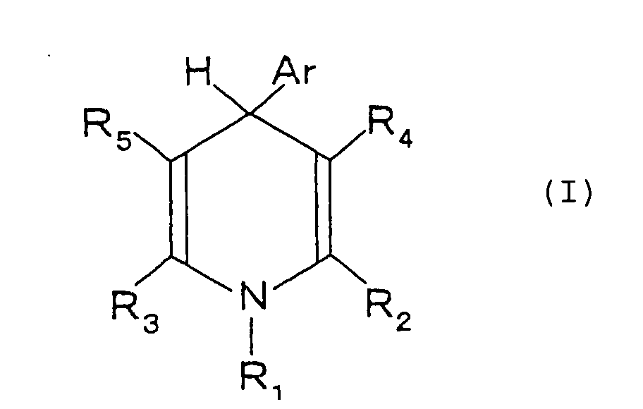
- The aromatic group Ar having a nitro group at the ortho position with respect to the bond to the 1,4-dihydropyridine ring is preferably a 2-nitrophenyl group. R1 is preferably -H, -CH3 or -(CH2)nCH3 (n is an integer of 1 to 4). R2 and R3 each preferably include -H, -CH3, and -(CH2)nCH3 (n is an integer of 1 to 4). R4 and R5 each preferably include -COORz and -CORz (Rz is a hydrogen atom or an alkyl group having 1 to 6 carbon atoms).
- Specific examples of the 1,4-dihydropyridine derivatives represented by formula (I) include 1-ethyl-3,5-dimethoxycarbonyl-4-(2-nitrophenyl)-1,4-dihydropyridine, 1-methyl-3,5-dimethoxycarbonyl-4-(2-nitrophenyl)-1,4-dihydropyridine, 1-propyl-3,5-dimethoxycarbonyl-4-(2-nitrophenyl)-1,4-dihydropyridine, 1-propyl-3,5-diethoxycarbonyl-4-(2-nitrophenyl)-1,4-dihydropyridine, 2,6-dimethyl-3,5-dimethoxycarbonyl-4-(2-nitrophenyl)-1,4-dihydropyridine (nifedipin), 2,6-dimethyl-3,5-diacetyl-4-(2-nitrophenyl)-1,4-dihydropyridine (acetyl form), and 1-ethyl-2,6-dimethyl-3,5-diacetyl-4-(2-nitrophenyl)-1,4-dihydropyridine.
- These 1,4-dihydropyridine derivatives can be used either singly or as a mixture of two or more thereof. Preferred of the 1,4-dihydropyridine derivatives are those which are inexpensive and show only a small absorption ascribed to the C-H bond stretch vibration in the near infrared region (useful as communication wavelengths), such as 1-ethyl-3,5-dimethoxycarbonyl-4-(2-nitrophenyl)-1,4-dihydropyridine. Further, in the case where the distance between glass fibers to be optically connected is long, for example, 1,000 µm or longer (preferably from 1,000 to 3,000 µm), 2,6-dimethyl-3,5-diacetyl-4-(2-nitrophenyl)-1,4-dihydropyridine (acetyl form), and 1-ethyl-2,6-dimethyl-3,5-diacetyl-4-(2-nitrophenyl)-1,4-dihydropyridine are preferred for reducing the connection loss.
- The 1,4-dihydropyridine derivative can be prepared, for example, by allowing a substituted benzaldehyde, double the molar quantity of an alkyl propionate (alkyl propargylate), and a corresponding primary amine to react in glacial acetic acid under reflux (see Khim Geterotsikl. Soed., 1982, 1067-1071).
- The resin for use in the resin composition is not particularly limited as long as it serves as a matrix capable of uniformly dissolving or dispersing the 1,4-dihydropyridine derivative. Examples of suitable resins include polyamic acid, polyimide, polyamide-imide, polycarbonate, polymethacrylates (e.g., polymethyl methacrylate), polyester (e.g., polyethylene terephthalate), polyether sulfone, polynorbornene, epoxy resins, polyaryl, polycarbodiimide, polyether imide, polyester imide, styrene resins (e.g., polystyrene, acrylonitrile-styrene copolymers, and acrylonitrile-butadiene-styrene copolymers), polyarylene ethers (e.g., polyphenylene ether), polyallylate, polyacetal, polyphenylene sulfide, polysulfone, polyether ketones (e.g., polyether ether ketone and polyether ketone ketone), polyvinyl alcohol, polyvinylpyrrolidone, fluorine resins (e.g., polyvinylidene fluoride resins, hexafluoropropylene resins, and hexafluoroacetone resins), and polysilane resins (including polyalkylsilanes (e.g., polymethylsilane), polyalkylcycloalkylsilanes (e.g., polymethylcyclohexylsilane), polyalkylarylsilanes (e.g., polymethylphenylsilane), and polyarylarylsilanes (e.g., polydiphenylsilane).
- From the standpoint of heat resistance, preferred of them are polyamic acid, polyimide, polyamide-imide, polyether imide, polyether ketones, epoxy resins, polycarbodiimide, fluorine resins, and polysilane resins.
- From the viewpoint of transparency, preferred are the above-described resins further having a halogen atom (e.g., fluorine) introduced therein, such as fluorinated polyamic acid, fluorinated polyimide, fluorinated polyamide-imide, fluorinated epoxy resins, and fluorine resins.
- In particular, polyamic acid (including fluorinated polyamic acid), polyimide (including fluorinated polyimide), and polyamide-imide (including fluorinated polyamide-imide) are practically useful.
- The polyamic acid can be obtained, for example, by allowing an organic tetracarboxylic acid dianhydride and a diamine to react.
- The organic tetracarboxylic acid dianhydride includes pyromellitic dianhydride, 3,3',4,4'-biphenyltetracarboxylic acid dianhydride, 2,2-bis(2,3-dicarboxyphenyl)propane dianhydride, 2,2-bis(3,4-dicarboxyphenyl)propane dianhydride, 3,3',4,4'-benzophenonetetracarboxylic acid dianhydride, bis(3,4-dicarboxyphenyl) ether dianhydride, and bis(3,4-dicarboxyphenyl)sulfonic acid dianhydride. Also included are halogen-substituted (e.g., fluorine-substituted) tetracarboxylic acid dianhydrides, such as 2,2-bis(2,3-dicarboxyphenyl)hexafluoropropane dianhydride, 2,2-bis(3,4-dicarboxypheyl)hexafluoropropane dianhydride, 4,4-bis(3,4-dicarboxytrifluorophenoxy)tetrafluorobenzene dianhydride, 1,4-bis(3,4-dicarboxytrifluorophenoxy)tetrafluorobenzene dianhydride, (trifluoromethyl)pyromellitic dianhydride, di(trifluoromethyl)pyromellitic dianhydride, and di(heptafluoropropyl)pyromellitic dianhydride.
- These organic tetracarboxylic acid dianhydrides can be used either singly or as a mixture of two or more thereof. Of the organic tetracarboxylic acid dianhydrides preferred are the halogen-substituted tetracarboxylic acid dianhydrides.
- The diamines include m-phenylenediamine, p-phenylenediamine, 3,4'-diaminodiphenyl ether, 4,4'-diaminodiphenyl ether, 4,4'-diaminodiphenyl sulfone, 3,3'-diaminodiphenyl sulfone, 2,2-bis(4-amiophenoxyphenyl)propane, 1,3-bis(4-aminophenoxy)benzene, 1,4-bis(4-aminophenoxy)benzene, 2,4-diaminotoluene, 2,6-diaminotoluene, 4,4'-diaminodiphenylmethane, and 4,4'-diamino-2,2'-dimethylbiphenyl. Also included are halogen-substituted (e.g., fluorine-substituted) diamines, such as 2,2'-bis(trifluoromethoxy)-4,4'-diaminobiphenyl (TFMOB), 3,3'-diamino-5,5'-bis(trifluoromethyl)biphenyl, 2,2-bis(4-aminophenyl)hexafluoropropane (BAAF), 2,2-bis[4-(4-aminophenoxy)phenyl]hexafluoropropane (HFBAPP), 2,2'-bis(trifluoromethyl)-4,4'-diaminobiphenyl (TFMB), 2,2-bis(3-amino-4-hydroxyphenyl)hexafluoropropane (BIS-AP-AF), 2,2-bis(3-amino-4-methylphenyl)hexafluoropropane (BIS-AT-AF), 2,2'-difluorobenzidine (FBZ), 4,4'-bis(aminooctafluoro)biphenyl, 3,5-diaminobenzotrifluoride, and 1,3-diamino-2,4,5,6-tetrafluorobenzene.
- These diamines can be used either singly or as a mixture of two or more thereof. Preferred of the diamines are halogen-substituted diamines.
- The polyamic acid can be obtained by allowing the organic tetracarboxylic acid dianhydride and the diamine to react in a known manner. The reaction is carried out, for example, by stirring the organic tetracarboxylic acid dianhydride and the diamine in an almost equimolar ratio in a reaction solvent in an inert gas atmosphere at 250°C or a lower temperature, preferably from room temperature (25°C) to 80°C, for about 5 to 20 hours to obtain a polyamic acid in the form of a viscous solution.
- The reaction solvent is not particularly limited as long as it is capable of dissolving both the starting materials (the organic tetracarboxylic acid dianhydride and the diamine) and the resulting polyamic acid. Suitable solvents include polar solvents, such as N-methyl-2-pyrrolidone, N,N-dimethylacetamide, N,N-diethylacetamide, and dimethyl sulfoxide. The polar solvents can be used either singly or as a mixture of two or more thereof. Of the recited polar solvents preferred is N,N-dimethylacetamide for its satisfactory resistance to thermal decomposition and excellent transparency.
- The polyamic acid thus obtained typically has a weight average molecular weight of about 5,000 to 500,000, preferably 10,000 to 150,000. The polyamic acid is obtained in the form of a solution of the reaction solvent, accounting for a proportion (solid concentration) of, typically, 1 to 50% by weight, preferably 5 to 30% by weight.
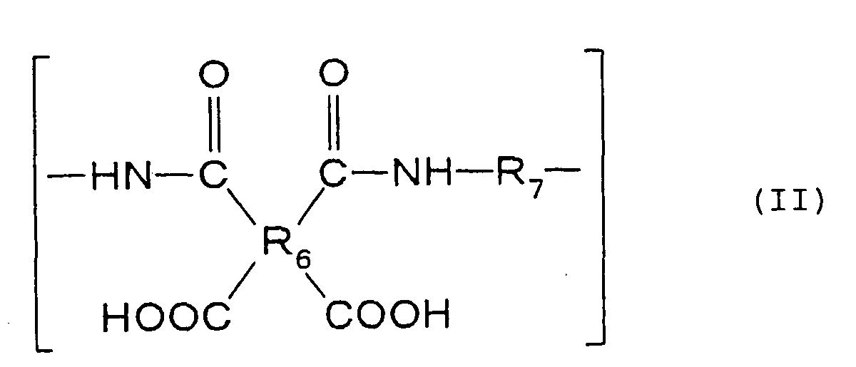
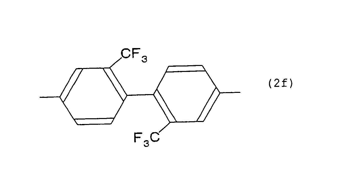
- Of the polyamic acids preferred are those comprising a repeating unit represented by formula (II) shown below for their low refractive index, which favors to control of a refractive index difference between a core and a clad in the optical waveguide formation described below.wherein R6 represents a tetravalent organic group selected from groups (2a), (2b), (2c), and (2d) shown below; and R7 represents a divalent organic group selected from the groups (2e), (2f), (2g), and (2g) shown below.






- Polyamic acids containing a halogen atom (e.g., fluorine) in the molecule thereof which are prepared using the halogen-substituted (e.g., fluorine-substituted) tetracarboxylic acid dianhydride and/or the halogen-substituted (e.g., fluorine-substituted) diamine exhibit improved transparency compared with halogen-free polyamic acids and therefore reduce the requisite amount of the 1,4-dihydropyridine derivative to be compounded therewith. In addition, the resin composition comprising the halogen-containing polyamic acid as a matrix resin has sufficient sensitivity even at a reduced irradiation dose to produce a sufficient contrast in refractive index.
- The polyimide, another example of the matrix resin, can be obtained, for example, by imidizing the above-described polyamic acid in a conventional manner. The polyamide-imide, a still other example of the matrix resin, can be obtained by partially imidizing the polyamic acid in a conventional manner. Of the polyimide and the polyamide-imide resins those containing a halogen atom (e.g., fluorine) in their molecule have the same advantages as with the halogen-containing polyamic acid. That is, the amount of the 1,4-dihydropyridine derivative to be compounded can be reduced, and the resin composition exhibits sufficient sensitivity even at a reduced irradiation dose to produce a sufficient contrast in refractive index.
- The resin composition for optical connection is prepared by compounding the 1,4-dihydropyridine derivative into the matrix resin. The amount of the 1,4-dihydropyridine derivative to be compounded is usually 0.1 to 30 parts by weight, preferably 1 to 5 parts by weight, per 100 parts by weight of the resin. With a 1,4-dihydropyridine derivative content of less than 0.1 part, the resin composition can fail to produce a sufficient difference in refractive index between irradiated and non-irradiated parts for forming an optical waveguide. If the 1,4-dihydropyridine derivative content exceeds 30 parts by weight, the composition tends to have an increased absorption in the near infrared region.
- The manner of compounding the 1,4-dihydropyridine derivative into the resin is not particularly restricted. For example, the 1,4-dihydropyridine derivative and the resin are mixed by stirring in an organic solvent capable of dissolving them. When a resin preliminary prepared in the form of a solution (such as the above-described polyamic acid solution) is used, the 1,4-dihydropyridine derivative can be added into the resin solution at a predetermined proportion as described above, followed by mixing.
- Where the resin composition is prepared as a solution, it is preferred to adjust the solution viscosity to, e.g., about 2 to 50 Pa.s, preferably about 5 to 20 Pa·s.
- In the first step of the process according to the invention, the resulting resin composition for optical connection is disposed between optical devices to be connected.
- The optical devices which can be connected by the technique of the present invention include, but are not limited to, optical fibers (single-mode optical fibers and multi-mode optical fibers), optical waveguides, light-emitting devices, e.g., laser diodes, and light-receiving devices, e.g., photodiodes.
- The manner of disposing the resin composition between optical devices is not particularly restricted. For example, as shown in Fig. 1A, a first
optical device 1 and a secondoptical device 3 which are to be optically connected are placed with a certain spacing with the input oroutput end 2 of the former and the input oroutput end 4 of the latter facing to each other. Then, as shown in Fig. 1B, theresin composition 5 is disposed between the input oroutput end 2 of the firstoptical device 1 and the input oroutput end 4 of the secondoptical device 3. - The first and the second
optical devices optical device 1 is composed of a columnar, high-refractive core 1a and a cylindrical, low-refractive clad 1b covering the whole circumference of thecore 1a. The input oroutput end 2 corresponds to the input or output end of thecore 1a. Similarly, the secondoptical device 3 is composed of a columnar, high-refractive core 3a and a cylindrical, low-refractive clad 3b covering the whole circumference of thecore 3a. The input oroutput end 4 corresponds to the input or output end of thecore 3a. - The first
optical device 1 and the secondoptical device 3 can be aligned with their input or output ends facing each other by means of an active alignment system based on light injection and detection. From economical considerations, alignment by image processing and V-groove alignment using a V-grooved substrate as an alignment aid, which is used for aligning optical fibers, etc., are preferably used. - As shown in Fig. 2A, alignment using a V-grooved substrate starts with preparation of a V-grooved
substrate 6 made of synthetic silica, etc. having a V-groove 7 in the direction of aligning the firstoptical device 1 and the second optical device 3 (longitudinal direction). The first and the secondoptical devices groove 7 with a predetermined spacing therebetween with their input or output ends facing each other as shown in Fig. 2B. Like this, optical devices to be connected can be aligned reliably with the aid of the V-groovedsubstrate 6 having a simple structure. - The distance (spacing) between the input or
output end 2 of the firstoptical device 1 and the input oroutput end 4 of the secondoptical device 3 is not particularly limited as far as light emitted from either end is transmitted through theresin composition 5 and made incident on the other. The distance is usually 30 mm or shorter, preferably 1 mm or shorter, still preferably 100 µm or shorter. At a distance longer than 30 mm, the loss of light transmitted through theresin composition 5 can be so large that the light emitted from one end may not be sufficiently inputted into the other. - The way of disposing the
resin composition 5 in the space between the first and the secondoptical devices - Fig. 2C represents an example of the
resin composition 5 in solution form having been dropped in the gap between the first and the secondoptical devices groove 7 of the V-groovedsubstrate 6. - In the second step of the process, light having a wavelength causing the 1,4-dihydropyridine derivative to change its structure is transmitted through the resin composition to form an optical path between the optical devices.
- Light for optical path formation is not particularly limited as long as the wavelength is such that the 1,4-dihydropyridine derivative undergoes structure change upon being irradiated. Various lasers can be used as a light source. The laser to be used is chosen according to the structure of the 1,4-dihydropyridine derivative. Where, for example, the 1,4-dihydropyridine derivative is 1-ethyl-3,5-dimethoxycarbonyl-4-(2-nitrophenyl)-1,4-dihydropyridine, 2,6-dimethyl-3,5-dimethoxycarbonyl-4-(2-nitrophenyl)-1,4-dihydropyridine, etc., which undergoes structural change on absorbing light having wavelengths at about 300 to 500 nm, a laser emitting light of a wavelength in that range, such as an He-Cd laser or an Ar laser, is employed.
- In addition to laser light, light emitted from a high-pressure mercury lamp, etc. for general exposure and condensed is also useful.
- As shown in Fig. 1C, light is led into the
input end 2a (reference character "a" will hereinafter be used for an input end, and "b" for an output end) of the firstoptical device 1 and transmitted through the firstoptical device 1. The light emitted from theoutput end 2b of the firstoptical device 1 is transmitted through theresin composition 5, made incident on theinput end 4a of the secondoptical device 3, transmitted through the secondoptical device 3, and emitted from theoutput end 4 of the secondoptical device 3. - The light emitted from the
output end 2b of the first optical device 1 (see Fig. 3A) propagates in theresin composition 5 without scattering (see Fig. 3B) and reaches theinput end 4a of the second optical device 3 (see Fig. 3C) to form anoptical path 8. - The 1,4-dihydropyridine derivative in the part where light has passed to form an
optical path 8 undergoes structural change into a substance that is hardly removed in the subsequent step of removal described below. - The structural change the 1,4-dihydropyridine derivative undergoes upon irradiation variously depends on the structure of the compound. However, release of hydrogen from the 1- and 4-positions to convert the pyridine ring to a Kekule structure can be mentioned as an example of the structural change.
- The light propagation direction in optical path formation is not limited to that of the embodiment shown in Fig. 1C. The light direction may be reversed as shown in Fig. 4A, in which light emitted from the
output end 4b of the secondoptical device 3 is transmitted through theresin composition 5, and made incident on theinput end 2a of the firstoptical device 1. It is also effective to guide light in two directions as shown in Fig. 4B, in which light is led into each of theinput end 2a of the firstoptical device 1 and theinput end 4a of the secondoptical device 3, transmitted through the first and the secondoptical devices output end 2b of the firstoptical device 1 and theoutput end 4b of the secondoptical device 3, respectively, and transmitted through theresin composition 5. This bidirectional optical path formation is advantageous in capable of forming a longeroptical path 8 between the optical devices. - In the embodiments shown in Figs. 1C, 4A, and 4B, the optical devices are aligned on the same axis to form a straight
optical path 8. Otherwise, it is possible to form a bent optical path as illustrated in Figs. 4C and 4D. In the embodiments shown in Figs. 4C and 4D, the firstoptical device 1 and the secondoptical device 3 are laid with their axes making a prescribed angle, amirror 9 is set near the intersection of the axes, and theresin composition 5 is disposed in the spacing between the first and the secondoptical devices mirror 9 therein. In the embodiment of Fig. 4C, light emitted from theoutput end 2b of the firstoptical device 1 is reflected on themirror 9 in theresin composition 5 and guided into theinput end 4a of the secondoptical device 3 to form a bentoptical path 8. In the embodiment of Fig. 4D, light is emitted from each of theoutput end 2b of the firstoptical device 1 and theoutput end 4b of the secondoptical device 3 in the same manner as in Fig. 4B and reflected on themirror 9 to form a bentoptical path 8. According to these embodiments, the optical devices can be optically connected even when some restriction of layout design, etc. does not allow formation of a straight optical path. - While not shown in the drawings, three or more optical devices can be connected by forming an
optical path 8 in every adjacent optical devices in the same manner as described above. - The irradiation dose to be applied is decided appropriately according to the kinds and amounts of the 1,4-dihydropyridine derivative and the resin, the wavelength of light, and the distance between the optical devices to be connected, and the like.
- In the third step of the process, the 1,4-dihydropyridine derivative is removed from the resin composition.
- The 1,4-dihydropyridine derivative does not always need to be removed completely. It suffices that the 1,4-dihydropyridine derivative is removed to such a degree as to result in a sufficient difference in refractive index between the irradiated and the non-irradiated parts of the resin composition for forming an optical waveguide.
- The method of removing the 1,4-dihydropyridine derivative includes, but is not limited to, (a) extraction and (b) heating.
- Removal by extraction is carried out, for example, by using an organic solvent capable of dissolving the 1,4-dihydropyridine derivative in accordance with general procedures of solvent extraction. Supercritical extraction using a supercritical fluid such as carbon dioxide is also effective.
- By extraction, the 1,4-dihydropyridine derivative that has not undergone structural change is extracted from the non-irradiated part of the resin composition, while the 1,4-dihydropyridine derivative that has undergone structural change remains in the irradiated part of the resin composition.
- Removal by heating is carried out by heating the resin composition at, e.g., 150° to 250°C, preferably 170° to 240°C.
- By heating, the 1,4-dihydropyridine derivative that has not undergone structural change vaporizes off the non-irradiated part of the resin composition, while the 1,4-dihydropyridine derivative that has undergone structural change remains in the irradiated part of the resin composition.
- It follows that the concentration of the 1,4-dihydropyridine derivative that has undergone structural change and remains in the optical path (i.e., the irradiated part) becomes higher than that of the 1,4-dihydropyridine derivative that has undergone no structural change in the other part (i.e., the non-irradiated part). As a result, the optical path exhibits a higher refractive index than the other part of the resin composition. As illustrated in Fig. 1D, there is thus formed an
optical waveguide 12 composed of the part having formed theoptical path 8 and functioning as a core 10 with a higher refractive index and the other part serving as a clad 11 with a lower refractive index, whereby the firstoptical device 1 and the secondoptical device 3 are connected optically. - The difference in refractive index between the core 10 and the clad 11 of the
optical waveguide 12, for example, where theoptical waveguide 12 is formed as single mode, the refractive index of a core is designated as n1, and the refractive index of a clad is designated as n2, is expressed in terms of a relative refractive index difference Δ (%) represented by equation: Δ=(n1-n2)/n1 x 100. The relative refractive index difference Δ preferably ranges from 0.2 to 0.5%. - Where the 1,4-dihydropyridine derivative is to be removed by heating the resin composition that has been disposed in solution form, it is preferable to preheat the resin composition to, e.g., about 80° to 120°C to preliminarily remove the organic solvent of the solution.
- Where the resin composition containing a polyamic acid as a matrix resin is heated to remove the 1,4-dihydropyridine derivative, the polyamic acid may be imidized by the heating simultaneously with removing the 1,4-dihydropyridine derivative thereby to impart improved heat resistance to the
optical waveguide 12. When heating is at a temperature in the above-recited range of 150° to 250°C, the polar solvent of the polyamic acid solution vaporizes and, at the same time, most of the polyamic acid is imidized to bring about improved heat resistance. Further heating at 300° to 400°C results in complete imidization of the polyamic acid to further improve the heat resistance. - According to the process of the present invention, an optical waveguide can be formed between a plurality of optical devices by simply disposing a resin composition prepared from a 1,4-dihydropyridine derivative and a resin between the optical devices to be connected, forming an optical path through the resin composition, and removing the 1,4-dihydropyridine derivative, to thereby optically connect the optical devices.
- In short, the process of the invention requires strict selection of the formulation for self-forming an optical waveguide. What is required is to prepare a resin composition from a 1,4-dihydropyridine derivative and a matrix resin. Simply by removing the 1,4-dihydropyridine derivative from the resin composition, a refractive index difference is easily produced between the irradiated part (an optical path) and the non-irradiated part to form a reliable optical waveguide. Reliable optical connection of optical devices can be achieved with a simpler formulation through a reduced number of steps without involving development processing. Thus, the optical connection structure of the present invention is inexpensive, easy to make, and reliable.
- The waveguide manufacturing process of the invention is applicable to optical connection of a wide variety of optical devices with no particular restriction. The optical waveguides which can be formed by the process include straight waveguides, bent waveguides, and intersecting waveguides.
- The optical devices to which the connection structure of the invention include wavelength filters, optical switches, optical branching parts, optical combining parts, optical branching/combining parts, optical amplifiers, wavelength converters, wavelength dividers, beam splitters, directional couplers, and hybrid optical transmission modules having a laser diode or a photodiode.
- The present invention will be illustrated in greater detail with reference to the following Examples, but the invention should not be construed as being limited thereto.
- In a 500 ml separable flask were put 16.0 g (0.05 mol) of 2,2'-bis(trifluoromethyl)-4,4'-diaminobiphenyl and 152.8 g of N,N-dimethylacetamide in a nitrogen atmosphere to prepare a solution.
- To the solution was added 22.2 g (0.05 mol) of 2,2-bis(3,4-dicarboxyphenyl)hexafluoropropane dianhydride while stirring, and the mixture was stirred at room temperature for 24 hours to prepare a polyamic acid solution.
- To the polyamic acid solution was added 1.91 g of 1-ethyl-3,5-dimethoxycarbonyl-4-(2-nitrophenyl)-1,4-dihydropyridine (corresponding to 5 parts per 100 parts of the polyamic acid on a solid basis) to prepare a resin composition in solution form.
- A V-grooved substrate of synthetic silica shown in Fig. 2 (groove depth: 20 mm; groove angle: 60°) was prepared. A single-mode glass fiber having an outer diameter of 125 µm (core diameter: 9.5 µm) and a multi-mode glass fiber (core diameter: 50.0 µm) were aligned in the V-groove at a distance of 100 µm, 500 µm, 1000 µm, and 1500 µm. The gap between the optical fibers was filled with the resin composition prepared above by dropping.
- The resin composition was preliminarily dried at 100°C for 20 minutes. Laser light (wavelength: about 490 nm) condensed through a condensing lens was made incident on the single-mode glass fiber, transmitted through the resin composition, and emitted from the multi-mode glass fiber for 5 minutes.
- The facing ends of the two glass fibers were observed under a stereomicroscope during laser light irradiation. It was found that a blue straight beam was emitted from the output end of the single-mode glass fiber, transmitted through the resin composition without diffusing, and guided into the input end of the multi-mode glass fiber.
- The resin composition was heated at 180°C for 10 minutes to remove the residual organic solvent and the 1,4-dihydropyridine derivative from the resin composition and to imidize the polyamic acid. A stereomicroscopic observation of the facing ends of the glass fibers during heating provided confirmation that the part where laser light had passed (where an optical path had been formed) slightly turned yellow, which indicated core formation.
- The resin composition was further heated in vacuo at 300°C for 1 hour to complete imidization of the polyamic acid.
- The connection loss of the resulting connection structure was measured using a semiconductor laser. As shown in Fig. 5, laser light emitted from a semiconductor (wavelength: 1.55 µm (5 mW)) was passed through a condensing lens, led into the single-mode glass fiber, transmitted through the optical connection made by the resin composition, and emitted from the multi-mode glass fiber. The emitted light was detected with an infrared detector (photodiode) to obtain the optical loss. The results are shown below.
Distance between Glass Fibers Connection Loss 100 µm 0.2 dB 500 µm 0.4 dB 1000 µm 0.9 dB 1500 µm 1.4 dB - Glass fibers were optically connected in the same manner as in Example 1, except that 1-ethyl-3,5-dimethoxycarbonyl-4-(2-nitrophenyl)-1,4-dihydropyridine was not added to the resin solution. The optical losses determined in the same manner as in Example 1 are shown below.
Distance between Glass Fibers Connection Loss 100 µm 1.2 dB 500 µm 2.2 dB 1000 µm 5.7 dB 1500 µm 9.8 dB - The same glass fibers as used in Example 1 were not optically connected with a resin composition. The optical losses due to the air gap between the glass fibers were as follows.
Distance between Glass Fibers Connection Loss 100 µm 2.3 dB 500 µm 9.5 dB 1000 µm 18.0 dB 1500 µm >20.0 dB (unmeasurable) - In a 500 ml separable flask were put 16.0 g (0.05 mol) of 2,2'-bis(trifluoromethyl)-4,4'-diaminobiphenyl and 152.8 g of N,N-dimethylacetamide in a nitrogen atmosphere to prepare a solution. To the solution was added 22.2 g (0.05 mol) of 2,2-bis(3,4-dicarboxyphenyl)hexafluoropropane dianhydride while stirring, and the mixture was stirred at room temperature for 24 hours to prepare a polyamic acid solution.
- The polyamic acid solution was diluted with N,N-dimethylacetamide to have a solid content of 10%. To the diluted solution were added 1.2 equivalent of pyridine per carboxylic acid equivalent of the polyamic acid and acetic anhydride to chemically imidize the polyamic acid. The precipitated polyimide was washed successively with large quantities of water and isopropyl alcohol, collected by filtration, and dried at 65°C under reduced pressure to obtain white flaky polyimide.
- The resulting polyimide was dissolved in N,N-dimethylacetamide to a concentration of 20%. To the solution was added 5 parts of 1-ethyl-3,5-dimethoxycarbonyl-4-(2-nitrophenyl)-1,4-dihydropyridine per 100 parts of the polyamic acid on a solid basis to prepare a resin composition in solution form.
- A V-grooved substrate of synthetic silica shown in Fig. 2 (groove depth: 20 mm; groove angle: 60°) was prepared. A single-mode glass fiber having an outer diameter of 125 µm (core diameter: 9.5 µm) and a multi-mode glass fiber (core diameter: 50.0 µm) were aligned in the V-groove at a distance of 100 µm, 500 µm, 1000 µm, and 1500 µm. The gap between the optical fibers was filled with the resin composition prepared above by dropping.
- The resin composition was preliminarily dried at 100°C for 20 minutes. Laser light (wavelength: about 490 nm) condensed through a condensing lens was made incident on the single-mode glass fiber, transmitted through the resin composition, and emitted from the multi-mode glass fiber for 5 minutes.
- The facing ends of the two glass fibers were observed under a stereomicroscope during laser light irradiation. It was found that a blue straight beam was emitted from the output end of the single-mode glass fiber, transmitted through the resin composition without diffusing, and guided into the input end of the multi-mode glass fiber.
- The resin composition was heated at 180°C for 10 minutes and then in vacuo at 220°C for 1 hour to remove the residual organic solvent and the 1,4-dihydropyridine derivative from the resin composition.
- The connection loss of the resulting connection structure was measured in the same manner as in Example 1. The results obtained are shown below.
Distance between Glass Fibers Connection Loss 100 µm 0.4 dB 500 µm 0.7 dB 1000 µm 1.2 dB 1500 µm 2.0 dB - Two multi-mode glass fibers were optically connected in the same manner as in Example 1. The optical losses measured in the same manner as in Example 1 were as follows.
Distance between Glass Fibers Connection Loss 100 µm 0.3 dB 500 µm 0.5 dB 1000 µm 1.1 dB 1500 µm 1.7 dB - Two glass fibers were optically connected in the same manner as in Example 1, except that the resin composition was prepared by adding 10 parts of 1-ethyl-3,5-dimethoxycarbonyl-4-(2-nitrophenyl)-1,4-dihydropyridine per 100 parts of the polyamic acid on a solid basis. The optical losses were as follows.
Distance between Glass Fibers Connection Loss 100 µm 0.3 dB 500 µm 0.4 dB 1000 µm 1.2 dB 1500 µm 1.9 dB - Two glass fibers were optically connected in the same manner as in Example 1, except for aligning two single-mode glass fibers and changing the fiber-to-fiber distance to 10 µm, 30 m, and 50 µm. The optical losses of the resulting optical connections were as follows.
Distance between Glass Fibers Connection Loss 10 µm 0.4 dB 30 µm 0.5 dB 50 µm 0.8 dB - Glass fibers were optically connected in the same manner as in Example 5, except that 1-ethyl-3,5-dimethoxycarbonyl-4-(2-nitrophenyl)-1,4-dihydropyridine was not added to the resin solution. The optical losses were as follows.
Distance between Glass Fibers Connection Loss 10 µm 1.3 dB 30 µm 2.5 dB 50 µm 5.8 dB - Glass fibers were optically connected in the same manner as in Example 1, except for replacing the 1-ethyl-3,5-dimethoxycarbonyl-4-(2-nitrophenyl)-1,4-dihydropyridine with 2,6-dimethyl-3,5-dimethoxycarbonyl-4-(2-nitrophenyl)-1,4-dihydropyridine. The optical losses due to the optical connection were as follows.
Distance between Glass Fibers Connection Loss 100 µm 0.2 dB 500 µm 0.4 dB 1000 µm 0.8 dB 1500 µm 1.5 dB - In a 500 ml separable flask were put 10.0 g (0.05 mol) of 4,4'-oxydianiline and 118.5 g of N,N-dimethylacetamide in a nitrogen atmosphere to prepare a solution. To the solution was added 10.9 g (0.05 mol) of pyromellitic dianhydride wile stirring, and the mixture was stirred at room temperature for 24 hours to prepare a polyamic acid solution.
- To the polyamic acid solution was added 2.09 g of 1-ethyl-3,5-dimethoxycarbonyl-4-(2-nitrophenyl)-1,4-dihydropyridine (corresponding to 10 parts per 100 parts of the polyamic acid on a solid basis) to prepare a resin composition in solution form.
- Glass fibers were optically connected using the resulting resin composition in the same manner as in
-
Distance between Glass Fibers Connection Loss 100 µm 0.3 dB 500 µm 0.5 dB 1000 µm 1.2 dB 1500 µm 1.7 dB - Glass fibers were optically connected in the same manner as in Example 1, except for replacing the 1-ethyl-3,5-dimethoxycarbonyl-4-(2-nitrophenyl)-1,4-dihydropyridine with 2,6-dimethyl-3,5-diacetyl-4-(2-nitrophenyl)-1,4-dihydropyridine (acetyl form). The optical losses due to the optical connection were as follows. In this Example, the measurement was also made for the cases where the distance between the glass fibers was 2,000 µm and 3,000 µm.
Distance between Glass Fibers Connection Loss .100 µm 0.2 dB 500 µm 0.2 dB 1000 µm 0.5 dB 1500 µm 0.8 dB 2000 µm 1.2 dB 3000 µm 3.0 dB - Glass fibers were optically connected in the same manner as in Example 1, except for replacing the 1-ethyl-3,5-dimethoxycarbonyl-4-(2-nitrophenyl)-1,4-dihydropyridine with 1-ethyl-2,6-dimethyl-3,5-diacetyl-4-(2-nitrophenyl)-1,4-dihydropyridine. The optical losses due to the optical connection were as follows. In this Example, the measurement was also made for the cases where the distance between the glass fibers was 2,000 µm and 3,000 µm.
Distance between Glass Fibers Connection Loss 100 µm 0.2 dB 500 µm 0.3 dB 1000 µm 0.7 dB 1500 µm 1.2 dB 2000 µm 2.0 dB 3000 µm 4.5 dB - According to the process of the invention, there is no need to strictly select the formulation for forming an optical waveguide. What is required is to prepare a resin composition from a 1,4-dihydropyridine derivative and a matrix resin. After optical path formation, a refractive index difference can be easily produced between the irradiated part (an optical path) and the non-irradiated part simply by removing the 1,4-dihydropyridine derivative from the resin composition thereby forming a reliable optical waveguide. Thus, optical connection of optical devices can surely be achieved with a simple formulation through only a few steps. Therefore, the optical device connection structure of the invention is inexpensive, easy to make, and reliable.
- While the present invention has been described in detail and with reference to specific embodiments thereof, it will be apparent to one skilled in the art that various changes and modifications can be made therein without departing from the spirit and scope thereof.
- This application is based on Japanese Patent Application No. 2003-15533 filed January 24, 2003, the contents thereof being incorporated herein by reference.
Claims (12)
- A process of manufacturing an optical waveguide for optically connecting a plurality of optical devices, comprising the steps of:disposing a resin composition between two or more optical devices, the resin composition comprising a resin and a 1,4-dihydropyridine derivative,forming an optical path through the resin composition between the optical devices by light having a wavelength capable of inducing a structural change in the 1,4-dihydropyridine derivative, andremoving the 1,4-dihydropyridine derivative from the resulting resin composition.
- The process according to claim 1, wherein the resin comprises at least one member selected from the group consisting of polyamic acid, polyimide and polyamide-imide.
- The process according to claim 1, wherein the resin composition contains 0.1 to 30 parts by weight of the 1,4-dihydropyridine derivative per 100 parts by weight of the resin.
- The process according to claim 3, wherein the resin composition contains 1 to 5 parts by weight of the 1,4-dihydropyridine derivative per 100 parts by weight of the resin.
- The process according to claim 1, wherein the 1,4-dihydropyridine derivative comprises a compound represented by formula (I):wherein Ar represents an aromatic group having a nitro group at the ortho position with respect to the bond to the 1,4-dihydropyridine ring; R1 represents -H, -CH3, -(CH2)nCH3, -CF3, -(CF2)nCF3, -C6H5, -(CH2)nC6H5, -CH2CH=CH2, -OH, -OCH3, -O(CH2)nCH3, -OCF3, -O(CF2)nCF3, -OC6H5, -O(CH2)nC6H5, -COOH, -COOCH3, -COO(CH2)nCH3, -COCH3, -CO(CH2)nCH3, -(CH2)nOH, -(CH2)nCOOH, -NOx, -F, -Cl, -Br or -I; R2 and R3, which may be the same or different, each represent -H, -CH3, -(CH2)nCH3, -CF3, -(CF2)nCF3, -OH, -OCH3, -O(CH2)nCH3, -OCF3, -O(CF2)nCF3, -COOCH3, -COO(CH2)nCH3, -COCH3, -CO(CH2)nCH3, -(CH2)nOH, -(CH2)nCOOH, -NOx, -F, -Cl, -Br or -I; R4 and R5, which may be the same or different, each represent -H, -CN, -COORz, -CORz or -CONHRz; n represents an integer of 1 to 4; and Rz represents a hydrogen atom or an alkyl group having 1 to 6 carbon atoms.

- The process according to claim 5, wherein R1 is -H, -CH3 or -(CH2)nCH3, R2 and R3 each independently represent -H, -CH3 or -(CH2)nCH3, R4 and R5 each independently represent -COORz or -CORz, wherein Rz is a hydrogen atom or an alkyl group having 1 to 6 carbon atoms and n is an integer of 1 to 4.
- The process according to claim 5, wherein the 1,4-dihydropyridine derivative comprises at least one compound selected from the group consisting of 1-ethyl-3,5-dimethoxycarbonyl-4-(2-nitrophenyl)-1,4-dihydropyridine, 1-methyl-3,5-dimethoxycarbonyl-4-(2-nitrophenyl)-1,4-dihydropyridine, 1-propyl-3,5-dimethoxycarbonyl-4-(2-nitrophenyl)-1,4-dihydropyridine, 1-propyl-3,5-diethoxycarbonyl-4-(2-nitrophenyl)-1,4-dihydropyridine, 2,6-dimethyl-3,5-dimethoxycarbonyl-4-(2-nitrophenyl)-1,4-dihydropyridine, 2,6-dimethyl-3,5-diacetyl-4-(2-nitrophenyl)-1,4-dihydropyridine, and 1-ethyl-2,6-dimethyl-3,5-diacetyl-4-(2-nitrophenyl)-1,4-dihydropyridine.
- The process according to claim 7, wherein the 1,4-dihydropyridine derivative comprises 1-ethyl-3,5-dimethoxycarbonyl-4-(2-nitrophenyl)-1,4-dihydropyridine.
- The process according to claim 7, wherein the 1,4-dihydropyridine derivative comprises at least one of 2,6-dimethyl-3,5-diacetyl-4-(2-nitrophenyl)-1,4-dihydropyridine and 1-ethyl-2,6-dimethyl-3,5-diacetyl-4-(2-nitrophenyl)-1,4-dihydropyridine.
- The process according to claim 1, wherein the resin comprises at least one member selected from the group consisting of polyamic acids, polyimides, and polyamide-imides.
- The process according to claim 10, wherein the resin is fluorinated.
- A connection structure of optical devices comprising:two or more optical devices; andat least one optical waveguide optically connecting the optical devices, the optical waveguide being formed by a process according to any one of claims 1 to 11.
Applications Claiming Priority (2)
| Application Number | Priority Date | Filing Date | Title |
|---|---|---|---|
| JP2003015533 | 2003-01-24 | ||
| JP2003015533 | 2003-01-24 |
Publications (1)
| Publication Number | Publication Date |
|---|---|
| EP1441243A1 true EP1441243A1 (en) | 2004-07-28 |
Family
ID=32588676
Family Applications (1)
| Application Number | Title | Priority Date | Filing Date |
|---|---|---|---|
| EP04001216A Withdrawn EP1441243A1 (en) | 2003-01-24 | 2004-01-21 | Process of manufacturing optical waveguide and connection structure of optical devices |
Country Status (4)
| Country | Link |
|---|---|
| US (1) | US7641821B2 (en) |
| EP (1) | EP1441243A1 (en) |
| KR (1) | KR100944310B1 (en) |
| CN (1) | CN100339732C (en) |
Cited By (2)
| Publication number | Priority date | Publication date | Assignee | Title |
|---|---|---|---|---|
| WO2009045339A1 (en) * | 2007-10-01 | 2009-04-09 | Corning Cable Systems Llc | Index-matching gel for nanostructure optical fibers and mechanical splice assembly and connector using same |
| US7742670B2 (en) | 2007-10-01 | 2010-06-22 | Corning Cable Systems Llc | Index-matching gel for nanostructure optical fibers and mechanical splice assembly and connector using same |
Families Citing this family (7)
| Publication number | Priority date | Publication date | Assignee | Title |
|---|---|---|---|---|
| US7037637B2 (en) * | 2002-07-17 | 2006-05-02 | Nitto Denko Corporation | Photosensitive polyimide resin precursor composition, optical polyimide obtained from the composition, optical waveguide using the polyimide, and process for producing the optical waveguide |
| JP2006036930A (en) * | 2004-07-27 | 2006-02-09 | Nitto Denko Corp | Resin for sealing optical semiconductor elements |
| US7949219B1 (en) | 2008-03-24 | 2011-05-24 | Lockheed Martin Corporation | Self forming waveguides for optical coupling and methodologies for making same |
| PL233284B1 (en) * | 2015-10-09 | 2019-09-30 | Wojskowa Akad Tech | Method for producing a polymer converter for joining optical fibres and the polymer converter for joining optical fibres |
| US11036015B2 (en) | 2017-06-07 | 2021-06-15 | Nippon Telegraph And Telephone Corporation | Connection structure of optical waveguide chips |
| US10487496B2 (en) | 2017-06-12 | 2019-11-26 | Robert Joe Alderman | Reflective temperature modulating blanket and architecture |
| JP7549354B2 (en) * | 2019-04-11 | 2024-09-11 | Orbray株式会社 | Optical connector and method for manufacturing the optical connector |
Citations (4)
| Publication number | Priority date | Publication date | Assignee | Title |
|---|---|---|---|---|
| JPS5543538A (en) * | 1978-09-20 | 1980-03-27 | Matsushita Electric Ind Co Ltd | Production of photo coupler |
| US5854868A (en) * | 1994-06-22 | 1998-12-29 | Fujitsu Limited | Optical device and light waveguide integrated circuit |
| US5902715A (en) * | 1992-11-09 | 1999-05-11 | Fujitsu Limited | Method of forming a mirror in a waveguide |
| US6081632A (en) * | 1994-06-22 | 2000-06-27 | Fujitsu Limited | Method of producing optical waveguide system, optical device and optical coupler employing the same, optical network and optical circuit board |
Family Cites Families (19)
| Publication number | Priority date | Publication date | Assignee | Title |
|---|---|---|---|---|
| US3809732A (en) * | 1972-12-18 | 1974-05-07 | Bell Telephone Labor Inc | Photo-locking technique for producing integrated optical circuits |
| JPS60173508A (en) | 1984-01-27 | 1985-09-06 | Nippon Telegr & Teleph Corp <Ntt> | Optical waveguide connecting method |
| EP0378156A3 (en) * | 1989-01-09 | 1992-02-26 | Nitto Denko Corporation | Positively photosensitive polyimide composition |
| JPH0777637A (en) | 1993-09-08 | 1995-03-20 | Fujitsu Ltd | Optical element coupling method and refractive index image forming material |
| JP3709997B2 (en) * | 1994-03-29 | 2005-10-26 | 日東電工株式会社 | Heat resistant negative photoresist composition, photosensitive substrate, and negative pattern forming method |
| JPH07333468A (en) * | 1994-06-03 | 1995-12-22 | Hitachi Ltd | Optical connection method |
| JPH08340422A (en) | 1995-06-09 | 1996-12-24 | Canon Inc | Image forming apparatus and motor control apparatus |
| JP3830181B2 (en) | 1995-08-23 | 2006-10-04 | 富士通株式会社 | Manufacturing method of optical interconnection cable |
| JPH1039510A (en) * | 1996-07-29 | 1998-02-13 | Nitto Denko Corp | Negative photoresist composition and use thereof |
| KR100265789B1 (en) | 1997-07-03 | 2000-09-15 | 윤종용 | Method for manual aligning the optical fibers |
| US6061632A (en) * | 1997-08-18 | 2000-05-09 | Trimble Navigation Limited | Receiver with seamless correction capacity |
| US6300037B1 (en) * | 1998-11-30 | 2001-10-09 | Nitto Denko Corporation | Photosensitive resin composition and adhesive |
| JP3444352B2 (en) | 1999-03-29 | 2003-09-08 | 株式会社豊田中央研究所 | Optical transmission line manufacturing method |
| JP2001267747A (en) * | 2000-03-22 | 2001-09-28 | Nitto Denko Corp | Method for manufacturing multilayer circuit board |
| JP2002040654A (en) * | 2000-07-31 | 2002-02-06 | Sumitomo Bakelite Co Ltd | Positive photosensitive resin composition |
| JP2002090559A (en) * | 2000-09-13 | 2002-03-27 | Minolta Co Ltd | Polyimide optical waveguide |
| JP3712934B2 (en) * | 2000-11-01 | 2005-11-02 | 株式会社日立製作所 | Optical waveguide member, manufacturing method thereof, and optical module |
| JP4446618B2 (en) | 2001-02-27 | 2010-04-07 | イビデン株式会社 | Method for forming optical waveguide |
| JP4799764B2 (en) * | 2001-05-31 | 2011-10-26 | 日東電工株式会社 | Photosensitive polyimide precursor composition for optical waveguide, photosensitive polyimide composition for optical waveguide, and optical waveguide using the same |
-
2004
- 2004-01-19 KR KR1020040003855A patent/KR100944310B1/en not_active Expired - Fee Related
- 2004-01-20 CN CNB2004100028978A patent/CN100339732C/en not_active Expired - Fee Related
- 2004-01-21 US US10/760,389 patent/US7641821B2/en not_active Expired - Fee Related
- 2004-01-21 EP EP04001216A patent/EP1441243A1/en not_active Withdrawn
Patent Citations (5)
| Publication number | Priority date | Publication date | Assignee | Title |
|---|---|---|---|---|
| JPS5543538A (en) * | 1978-09-20 | 1980-03-27 | Matsushita Electric Ind Co Ltd | Production of photo coupler |
| US5902715A (en) * | 1992-11-09 | 1999-05-11 | Fujitsu Limited | Method of forming a mirror in a waveguide |
| US6017681A (en) * | 1992-11-09 | 2000-01-25 | Fujitsu Limited | Method of coupling optical parts and method of forming a mirror |
| US5854868A (en) * | 1994-06-22 | 1998-12-29 | Fujitsu Limited | Optical device and light waveguide integrated circuit |
| US6081632A (en) * | 1994-06-22 | 2000-06-27 | Fujitsu Limited | Method of producing optical waveguide system, optical device and optical coupler employing the same, optical network and optical circuit board |
Non-Patent Citations (1)
| Title |
|---|
| PATENT ABSTRACTS OF JAPAN vol. 0040, no. 78 (P - 014) 6 June 1980 (1980-06-06) * |
Cited By (4)
| Publication number | Priority date | Publication date | Assignee | Title |
|---|---|---|---|---|
| WO2009045339A1 (en) * | 2007-10-01 | 2009-04-09 | Corning Cable Systems Llc | Index-matching gel for nanostructure optical fibers and mechanical splice assembly and connector using same |
| US7628548B2 (en) | 2007-10-01 | 2009-12-08 | Corning Cable Systems Llc | Index-matching gel for nanostructure optical fibers and mechanical splice assembly and connector using same |
| US7742670B2 (en) | 2007-10-01 | 2010-06-22 | Corning Cable Systems Llc | Index-matching gel for nanostructure optical fibers and mechanical splice assembly and connector using same |
| US8152387B2 (en) | 2007-10-01 | 2012-04-10 | Corning Cable Systems Llc | Index-matching gel for nanostructure optical fibers and mechanical splice assemble and connector using same |
Also Published As
| Publication number | Publication date |
|---|---|
| US20040178522A1 (en) | 2004-09-16 |
| CN100339732C (en) | 2007-09-26 |
| KR20040068470A (en) | 2004-07-31 |
| US7641821B2 (en) | 2010-01-05 |
| KR100944310B1 (en) | 2010-02-24 |
| CN1517729A (en) | 2004-08-04 |
Similar Documents
| Publication | Publication Date | Title |
|---|---|---|
| US7037637B2 (en) | Photosensitive polyimide resin precursor composition, optical polyimide obtained from the composition, optical waveguide using the polyimide, and process for producing the optical waveguide | |
| US7641821B2 (en) | Process of manufacturing optical waveguide and connection structure of optical devices | |
| KR100837024B1 (en) | Process for producing polyimide optical waveguide | |
| KR100798218B1 (en) | Manufacturing method of three-dimensional polyimide optical waveguide | |
| JP4799764B2 (en) | Photosensitive polyimide precursor composition for optical waveguide, photosensitive polyimide composition for optical waveguide, and optical waveguide using the same | |
| JP3841288B2 (en) | Photosensitive polyimide resin precursor composition, optical polyimide and optical waveguide obtained therefrom | |
| JP4010011B2 (en) | Optical waveguide structure | |
| US7236675B2 (en) | Process for producing optical waveguide | |
| JP4213573B2 (en) | Optical waveguide manufacturing method and optical device connection structure | |
| JP4231768B2 (en) | Photosensitive polyamic acid composition, optical polyimide resin and optical waveguide obtained therefrom | |
| JP2005165138A (en) | Optical waveguide | |
| JP2002243960A (en) | Filter type multi-channel polymer wavelength multiplexer / demultiplexer | |
| JP2008046657A (en) | S-shape curved optical waveguide and optical device | |
| Mune et al. | Fabrication of low-loss optical waveguides using a novel photosensitive polyimide | |
| JP2007219560A (en) | Optical waveguide structure | |
| JP2005017429A (en) | Manufacturing method of optical waveguide | |
| JP4423668B2 (en) | Optical waveguide | |
| Mune et al. | New fabrication method of self-written waveguide by using photosensitive polyimide | |
| JP2005148174A (en) | V-groove substrate and manufacturing method thereof | |
| JP2004170578A (en) | Optical coupling method using optical waveguide |
Legal Events
| Date | Code | Title | Description |
|---|---|---|---|
| PUAI | Public reference made under article 153(3) epc to a published international application that has entered the european phase |
Free format text: ORIGINAL CODE: 0009012 |
|
| AK | Designated contracting states |
Kind code of ref document: A1 Designated state(s): AT BE BG CH CY CZ DE DK EE ES FI FR GB GR HU IE IT LI LU MC NL PT RO SE SI SK TR |
|
| AX | Request for extension of the european patent |
Extension state: AL LT LV MK |
|
| 17P | Request for examination filed |
Effective date: 20041025 |
|
| AKX | Designation fees paid |
Designated state(s): DE FR GB |
|
| 17Q | First examination report despatched |
Effective date: 20061219 |
|
| STAA | Information on the status of an ep patent application or granted ep patent |
Free format text: STATUS: THE APPLICATION IS DEEMED TO BE WITHDRAWN |
|
| 18D | Application deemed to be withdrawn |
Effective date: 20151006 |