EP1440780B1 - Nadelverschlussdüse zur Befüllung eines Werkzeuges mit einem flüssigen organischen Material sowie Verfahren zur Herstellung eines optischen Elements unter Verwendung einer solchen Düse - Google Patents
Nadelverschlussdüse zur Befüllung eines Werkzeuges mit einem flüssigen organischen Material sowie Verfahren zur Herstellung eines optischen Elements unter Verwendung einer solchen Düse Download PDFInfo
- Publication number
- EP1440780B1 EP1440780B1 EP04290124A EP04290124A EP1440780B1 EP 1440780 B1 EP1440780 B1 EP 1440780B1 EP 04290124 A EP04290124 A EP 04290124A EP 04290124 A EP04290124 A EP 04290124A EP 1440780 B1 EP1440780 B1 EP 1440780B1
- Authority
- EP
- European Patent Office
- Prior art keywords
- needle
- flow
- filling
- valve
- flowrate
- Prior art date
- Legal status (The legal status is an assumption and is not a legal conclusion. Google has not performed a legal analysis and makes no representation as to the accuracy of the status listed.)
- Expired - Lifetime
Links
- 238000000465 moulding Methods 0.000 title claims description 54
- 230000003287 optical effect Effects 0.000 title claims description 22
- 238000000034 method Methods 0.000 title claims description 17
- 239000011368 organic material Substances 0.000 title claims description 8
- 239000007788 liquid Substances 0.000 title claims description 7
- 230000008569 process Effects 0.000 title description 3
- 239000000463 material Substances 0.000 claims description 51
- 238000006116 polymerization reaction Methods 0.000 claims description 8
- 230000008859 change Effects 0.000 claims description 7
- 238000011144 upstream manufacturing Methods 0.000 claims description 7
- 229920001343 polytetrafluoroethylene Polymers 0.000 claims description 5
- 239000004810 polytetrafluoroethylene Substances 0.000 claims description 5
- 230000000379 polymerizing effect Effects 0.000 claims description 2
- 229920002943 EPDM rubber Polymers 0.000 claims 1
- 239000012778 molding material Substances 0.000 description 19
- 238000001595 flow curve Methods 0.000 description 9
- 230000007547 defect Effects 0.000 description 8
- 238000005266 casting Methods 0.000 description 6
- 230000000694 effects Effects 0.000 description 6
- 238000006073 displacement reaction Methods 0.000 description 4
- 238000004519 manufacturing process Methods 0.000 description 4
- 239000000203 mixture Substances 0.000 description 4
- 208000031968 Cadaver Diseases 0.000 description 3
- 241000287107 Passer Species 0.000 description 3
- -1 Polytetrafluoroethylene Polymers 0.000 description 3
- 238000013016 damping Methods 0.000 description 3
- 239000012530 fluid Substances 0.000 description 3
- 230000000630 rising effect Effects 0.000 description 3
- 229920002994 synthetic fiber Polymers 0.000 description 3
- 239000006188 syrup Substances 0.000 description 3
- 235000020357 syrup Nutrition 0.000 description 3
- 238000013519 translation Methods 0.000 description 3
- 229920000297 Rayon Polymers 0.000 description 2
- 230000008901 benefit Effects 0.000 description 2
- 235000021183 entrée Nutrition 0.000 description 2
- 238000012423 maintenance Methods 0.000 description 2
- 239000002184 metal Substances 0.000 description 2
- 230000005855 radiation Effects 0.000 description 2
- 239000002964 rayon Substances 0.000 description 2
- 238000010008 shearing Methods 0.000 description 2
- 125000006850 spacer group Chemical group 0.000 description 2
- 230000007704 transition Effects 0.000 description 2
- XLYOFNOQVPJJNP-UHFFFAOYSA-N water Substances O XLYOFNOQVPJJNP-UHFFFAOYSA-N 0.000 description 2
- 238000009736 wetting Methods 0.000 description 2
- 241001416181 Axis axis Species 0.000 description 1
- 230000001133 acceleration Effects 0.000 description 1
- 239000011248 coating agent Substances 0.000 description 1
- 238000000576 coating method Methods 0.000 description 1
- 230000000295 complement effect Effects 0.000 description 1
- 239000000470 constituent Substances 0.000 description 1
- 238000005520 cutting process Methods 0.000 description 1
- 230000000593 degrading effect Effects 0.000 description 1
- 230000001419 dependent effect Effects 0.000 description 1
- 229920001971 elastomer Polymers 0.000 description 1
- 239000000806 elastomer Substances 0.000 description 1
- 238000002474 experimental method Methods 0.000 description 1
- 239000011521 glass Substances 0.000 description 1
- 230000005484 gravity Effects 0.000 description 1
- 239000011344 liquid material Substances 0.000 description 1
- 210000000056 organ Anatomy 0.000 description 1
- 235000012830 plain croissants Nutrition 0.000 description 1
- 230000007425 progressive decline Effects 0.000 description 1
- 230000000750 progressive effect Effects 0.000 description 1
- 238000005086 pumping Methods 0.000 description 1
- 230000009257 reactivity Effects 0.000 description 1
- 238000005201 scrubbing Methods 0.000 description 1
- 238000012360 testing method Methods 0.000 description 1
Images


Classifications
-
- F—MECHANICAL ENGINEERING; LIGHTING; HEATING; WEAPONS; BLASTING
- F16—ENGINEERING ELEMENTS AND UNITS; GENERAL MEASURES FOR PRODUCING AND MAINTAINING EFFECTIVE FUNCTIONING OF MACHINES OR INSTALLATIONS; THERMAL INSULATION IN GENERAL
- F16K—VALVES; TAPS; COCKS; ACTUATING-FLOATS; DEVICES FOR VENTING OR AERATING
- F16K1/00—Lift valves or globe valves, i.e. cut-off apparatus with closure members having at least a component of their opening and closing motion perpendicular to the closing faces
- F16K1/32—Details
- F16K1/34—Cutting-off parts, e.g. valve members, seats
- F16K1/36—Valve members
- F16K1/38—Valve members of conical shape
-
- B—PERFORMING OPERATIONS; TRANSPORTING
- B29—WORKING OF PLASTICS; WORKING OF SUBSTANCES IN A PLASTIC STATE IN GENERAL
- B29C—SHAPING OR JOINING OF PLASTICS; SHAPING OF MATERIAL IN A PLASTIC STATE, NOT OTHERWISE PROVIDED FOR; AFTER-TREATMENT OF THE SHAPED PRODUCTS, e.g. REPAIRING
- B29C33/00—Moulds or cores; Details thereof or accessories therefor
- B29C33/0061—Moulds or cores; Details thereof or accessories therefor characterised by the configuration of the material feeding channel
-
- B—PERFORMING OPERATIONS; TRANSPORTING
- B29—WORKING OF PLASTICS; WORKING OF SUBSTANCES IN A PLASTIC STATE IN GENERAL
- B29C—SHAPING OR JOINING OF PLASTICS; SHAPING OF MATERIAL IN A PLASTIC STATE, NOT OTHERWISE PROVIDED FOR; AFTER-TREATMENT OF THE SHAPED PRODUCTS, e.g. REPAIRING
- B29C45/00—Injection moulding, i.e. forcing the required volume of moulding material through a nozzle into a closed mould; Apparatus therefor
- B29C45/17—Component parts, details or accessories; Auxiliary operations
- B29C45/26—Moulds
- B29C45/27—Sprue channels ; Runner channels or runner nozzles
- B29C45/28—Closure devices therefor
-
- B—PERFORMING OPERATIONS; TRANSPORTING
- B29—WORKING OF PLASTICS; WORKING OF SUBSTANCES IN A PLASTIC STATE IN GENERAL
- B29D—PRODUCING PARTICULAR ARTICLES FROM PLASTICS OR FROM SUBSTANCES IN A PLASTIC STATE
- B29D11/00—Producing optical elements, e.g. lenses or prisms
- B29D11/00009—Production of simple or compound lenses
- B29D11/00413—Production of simple or compound lenses made by moulding between two mould parts which are not in direct contact with one another, e.g. comprising a seal between or on the edges
-
- B—PERFORMING OPERATIONS; TRANSPORTING
- B29—WORKING OF PLASTICS; WORKING OF SUBSTANCES IN A PLASTIC STATE IN GENERAL
- B29D—PRODUCING PARTICULAR ARTICLES FROM PLASTICS OR FROM SUBSTANCES IN A PLASTIC STATE
- B29D11/00—Producing optical elements, e.g. lenses or prisms
- B29D11/00009—Production of simple or compound lenses
- B29D11/00432—Auxiliary operations, e.g. machines for filling the moulds
-
- B—PERFORMING OPERATIONS; TRANSPORTING
- B29—WORKING OF PLASTICS; WORKING OF SUBSTANCES IN A PLASTIC STATE IN GENERAL
- B29C—SHAPING OR JOINING OF PLASTICS; SHAPING OF MATERIAL IN A PLASTIC STATE, NOT OTHERWISE PROVIDED FOR; AFTER-TREATMENT OF THE SHAPED PRODUCTS, e.g. REPAIRING
- B29C45/00—Injection moulding, i.e. forcing the required volume of moulding material through a nozzle into a closed mould; Apparatus therefor
- B29C45/0025—Preventing defects on the moulded article, e.g. weld lines, shrinkage marks
-
- B—PERFORMING OPERATIONS; TRANSPORTING
- B29—WORKING OF PLASTICS; WORKING OF SUBSTANCES IN A PLASTIC STATE IN GENERAL
- B29C—SHAPING OR JOINING OF PLASTICS; SHAPING OF MATERIAL IN A PLASTIC STATE, NOT OTHERWISE PROVIDED FOR; AFTER-TREATMENT OF THE SHAPED PRODUCTS, e.g. REPAIRING
- B29C45/00—Injection moulding, i.e. forcing the required volume of moulding material through a nozzle into a closed mould; Apparatus therefor
- B29C45/0046—Details relating to the filling pattern or flow paths or flow characteristics of moulding material in the mould cavity
-
- B—PERFORMING OPERATIONS; TRANSPORTING
- B29—WORKING OF PLASTICS; WORKING OF SUBSTANCES IN A PLASTIC STATE IN GENERAL
- B29C—SHAPING OR JOINING OF PLASTICS; SHAPING OF MATERIAL IN A PLASTIC STATE, NOT OTHERWISE PROVIDED FOR; AFTER-TREATMENT OF THE SHAPED PRODUCTS, e.g. REPAIRING
- B29C45/00—Injection moulding, i.e. forcing the required volume of moulding material through a nozzle into a closed mould; Apparatus therefor
- B29C45/17—Component parts, details or accessories; Auxiliary operations
- B29C45/26—Moulds
- B29C45/27—Sprue channels ; Runner channels or runner nozzles
- B29C45/28—Closure devices therefor
- B29C45/2803—Closure devices therefor comprising a member with an opening or the injection nozzle movable into or out of alignment with the sprue channel or mould gate
-
- B—PERFORMING OPERATIONS; TRANSPORTING
- B29—WORKING OF PLASTICS; WORKING OF SUBSTANCES IN A PLASTIC STATE IN GENERAL
- B29L—INDEXING SCHEME ASSOCIATED WITH SUBCLASS B29C, RELATING TO PARTICULAR ARTICLES
- B29L2011/00—Optical elements, e.g. lenses, prisms
- B29L2011/0016—Lenses
Definitions
- the present invention relates generally to the manufacture by molding of organic optical elements, such as corrective and / or solar ophthalmic lenses, instrument lenses or precision optics. It is more specifically concerned with the filling of a mold with the organic material in the liquid state and has for its object a valve intended to control this filling.
- the molding of an optical element such as an ophthalmic lens is done using a mold formed of two molding shells on the periphery of which is established annularly a closure element defining with them the molding cavity sought .
- the initialization of the polymerization of this material is provided by a source of heat or radiation.
- US 4474356 discloses a needle valve according to the preamble of claim 1.
- the molding material is introduced into the molding cavity through an opening which is duly provided for this purpose on the periphery of the molding shells (in practice, most often in the element closing), so as not to interfere with the optically useful area of the formed optical lens.
- This filling phase is effected by means of a filling device capable of delivering a determined dose of molding material.
- This filling device comprises a nozzle for introducing the material into the mold, associated with the filling opening of the mold. Upstream of the nozzle, separately or in one piece with it, is provided a valve whose control, preferably automated, must allow a precise dosage of the amount of material delivered to the mold, at a sufficient rate.
- the filling device itself has in fact a more or less uneven internal pipe, inside which the molding material undergoes, at least to a certain extent, certain flow disturbances which, with regard to the speed of filling and the viscosity of the molding material, oppose a laminar flow and generate, without the process is well controlled, the appearance of microbubbles.
- the portion of the molding cavity located around the filling opening has irregularities, resulting in particular from the presence of the nose of the filling nozzle which opens at this point in the mold. These surface irregularities of the molding cavity may create irregularities of flow causing the appearance of microbubbles.
- the material may suffer irregularities in flow, or even jolts.
- this molding material is a mixture of constituents which may have different refractive indices and / or viscosity coefficients, it may result, by shearing or stretching, the appearance of relatively large local index gradients, which, if the polymerization occurs too quickly after filling, do not fail to lead to other optical defects such as the effect of "syrup "well known glassmakers.
- the valve can appear as a particularly sensitive organ insofar as, to perform its functions of opening, closing and flow control, it operates variations in the flow section, generating turbulence or turbulence. cavitation phenomena or the like causing optical defects of the optical element finally obtained.
- the invention proposes a valve that preserves the optical integrity of the material to be molded during its flow, including opening and closing.
- the closing shoulder of the needle is blunted and the recess of the flow channel is conical.
- the invention also relates to a method of molding an optical element of organic material in a suitable molding cavity, comprising a filling sequence of the molding cavity with organic material in the liquid state and a step of polymerization of the material in said molding cavity, wherein the filling sequence of the molding cavity is effected by means of a valve according to the invention.
- the valve needle can be controlled in speed or position.
- the mold cavity is slowly filled so as to "wet" with the mold material the bottom of the mold until a certain minimum volume of material is present therein. be introduced. Because it is the beginning of the filling of the mold which seems to be the most critical. Thanks to the slowness of the flow during this beginning of filling, the small volume of material thus initially introduced remains free microbubbles or at least, in case of appearance of a few microbubbles, frees them easily because of its low height.
- the filling can be accelerated without risk of turbulence, because on the one hand the volume of material already introduced exerts a fluid damping function and secondly the speed of progression of the free surface of the material in the mold is less constant flow, the molding cavity widening.
- the material is introduced into the molding cavity through an orifice located in the lower part of said cavity and the polymerization of the material is initiated immediately after filling.
- This phase of slow start of filling makes it possible to "wet" gently the lower part of the wetting cavity which is precisely that in which the filling opening and in particular the nose of the filling nozzle are located. It also avoids any jet effect (by analogy to a jet of water, proportionately kept) that would result from a filling start too fast.
- FIG. 1 represents a device for molding an optical element made of synthetic material such as an ophthalmic lens intended to equip a pair of corrective or solar glasses.
- This molding device generally consists of two parts: a mold 1 enclosing the molding cavity defining the lens to be molded and a filling device 15.
- the mold 1 does not fall within its details of the present invention and it will therefore only be briefly described. In the context of the present invention, it will also be possible to use any kind of mold, with the corresponding molding process. Thus, for example, molds and methods of the type described in EP 0715946, US 4190621 and US 5110514 may be used, the mold and molding method descriptions of which are incorporated in the present description.
- the mold 1 is of the type described in the document EP 0715946. It comprises two jaws 2, 3 each having an inner hemicylindrical surface complementary to the other and enclosing two molding shells 4, 5 arranged in a voice, following a vertical plane.
- the two shells 4, 5 define between them the desired molding cavity 6.
- the two jaws 2, 3 are carried by a frame 7 and the upper jaw 3 is movable in vertical translation under the control of jacks 8.
- the lower jaw 2 has a pouring orifice 9 located at the lower part of the molding cavity 6 and, preferably, at the lowest point thereof.
- the pouring orifice 9 opens on the lowest generatrix of the inner surface of the jaw 2; it is arranged along a vertical casting axis 11.
- the upper jaw 3 itself has a vent 10 of the same vertical axis 11 located in the upper part and opening preferentially to the highest generatrix of the inner surface of the jaw 3.
- the filling device 15 of the molding cavity is a device for ensuring filling the molding cavity with the desired amount of synthetic material, without generating microbubbles or syrup effect, in order to obtain a molded element of good optical quality.
- the filling device 15 is connected by a conduit 16 to supply means (not shown) able to ensure a continuous supply of the molding cavity molding material.
- Continuous feeding means here a substantially constant pressure feed, devoid of any sudden.
- These supply means comprise, for example, a source of pressure arranged upstream of a reservoir which, forming a nurse, contains the molding material and which, via the duct 16, is connected to the filling device.
- the pressure source is a compressed air reservoir which, under the control of a regulator, is connected to the reservoir, above the molding material contained therein.
- the molding material may optionally be a composition at least partially polymerizable by exposure, and, for example, ultraviolet radiation, or be a composition at least partly heat-curable, or still be a composition which is both heat-insoluble polymerizable and heat-curable.
- the filling device 15 comprises two main components arranged along the casting axis 11: a nozzle 17 and a needle valve 18.
- the nozzle 17 is generally of revolution around the casting axis 11 and is externally staggered in three sections, with a fixing plate 19, a cylindrical or parallelepiped body 20 received in a corresponding housing of the lower jaw 4 of the mold, and a tip 21 through a corresponding hole of the lower jaw 4 to open flush on the inner face of the jaw.
- the nozzle 17 comprises a through inner channel 22 of axis 11 which, at its upper end, opens into the mold cavity 6 to form the casting orifice 9 mentioned above.
- valve 18 Below the nozzle 17, that is to say upstream thereof with reference to the direction of flow of the material to be molded, is mounted the valve 18.
- This valve comprises a body 25 generally of revolution around the casting axis 11, provided with an upper fixing flange 26 pressed against the fixing plate 19 of the nozzle 17 by means of screws 28 which, passing through the flange 26 and the plate 19, are engaged in corresponding threads of the jaw 4 to fix the jaw 4 to both the nozzle 17 and the body 25 of the valve 18.
- a flow channel 30 of the molding material is provided inside valve body 18. This channel has an inlet opening 31, an outlet opening 32 and, between these two openings, a constriction 33 bordered on its upstream side by a recess 34 forming seat as will be better explained later.
- the flow channel 30 here has a shape of L, having a first branch, vertical, of revolution about the flow axis 11 and whose free end constitutes the outlet opening 32, and a second branch, horizontal, of revolution about an axis 35 perpendicular to the axis of flow 11. This second branch may also not be perpendicular to the axis 11
- the first leg of the channel 30 is stepped, with a wide base 36 and, at the end, the narrowing 33 followed by the outlet opening 32.
- the base 36 and the narrowing 33 are cylindrical.
- the narrowing 33 has a diameter equal to that of the outlet opening 32 which therefore forms the extension.
- the transition between the wide base 36 and the narrowing 33 is performed by the recess 34 which is conically shaped and which is connected to the narrowing 33 and the base 36 by dull connection zones, that is to say non-angular .
- This uniformity of section downstream of the recess 34 and the softness of the diameter transition resulting from the taper of the recess 34 and the absence of angular zone make it possible to avoid or at least to limit for the most part the turbulence of flow.
- a top angle of between 30 and 60 degrees will preferably be chosen. It is however not essential that the recess 34 be strictly tapered. It may even be interesting to make this recess in the form of a surface of revolution of curved axial section, for example close to a toric surface or even more complex with a corrugated axial section for a smooth connection with the wide base 36 and narrowing 33.
- the internal channel 22 of the nozzle 17 is, at least in its part adjacent to the outlet opening 32, cylindrical in shape with the same diameter as said outlet opening 32.
- the flow of the molding material does not encounter any irregularity between the valve 18 and the nozzle 17.
- the second branch of the flow channel 30 is reduced to the inlet opening 31 which opens directly to the base of the first branch. Upstream (relative to the direction of flow), the inlet opening 31 opens into a threaded housing 37 intended to receive a threaded connection end of the conduit 16.
- the valve 18 further comprises a needle 40 mounted in the body 25 to be movable between a fully open position allowing a maximum flow and a closed position closing the flow channel 30, with, between these two extreme positions, a range intermediate positions on which the flow rate allowed by the valve 18 varies.
- This needle 40 has an axis of symmetry of revolution and is mounted in the body 25 to slide along its axis which merges with the flow axis 11. More specifically, the needle 40 comprises an elongated base 41 of cylindrical outer surface of 11 and an elongated nose 42 along the axis 11, exerting, in cooperation with the constriction 33 of the flow channel 30, a flow control function and having for this purpose a non-uniform section over its entire length, as this will be better explained later.
- the elongated cylindrical base 41 is slidably received in a through bore 45 formed in the body 25 along the axis 11.
- An O-ring seal 44 made of an elastomer of the Ethylene-Propylene-Diene type is mounted between the body 25 and the cylindrical base 41 of the needle.
- the nose 42 has a conical outer surface making it possible to establish, at constant pressure of admission of the material to be molded, a function of correspondence between the axial position of the needle 40 and the flow rate. delivered by the valve 18. Indeed, in the intermediate positions of the needle 40, the conical nose 42 of the needle 41 is engaged in the narrowing 33 of the flow channel 30 and it is understood that the degree of depression of the nose 42 in the narrowing 33, depends the flow section left free for the material to be molded between said nose and the narrowing 33. For a given inlet pressure of the molding material, the flow rate authorized by the valve 18 can be adjusted by adjusting the position of the needle 40 along its axis 11.
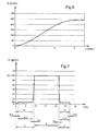
- FIG. 6 shows the material flow curve, denoted by Q and given in ordinate in g / min, as a function of the axial position of the needle 41, denoted x and appearing on the abscissa in mm.
- the axial position of the needle 41 is marked from its closed position, origin of the abscissae, and extends to its maximum open position which is here at 3.5 mm from its closed position where the flow reaches nearly 250 g / min.
- the nose 42 has a free end 46 which is blunt and more precisely, in this case, spherical.
- This blunt configuration of the end of the nose 42 avoids or at least limit turbulence during the flow.
- the end of the nose 42 is, when flowing in partial open position, engaged in the constriction 33.
- the maximum open position ( 4) in which the flow velocity is the highest the end 46 of the nose 42 is at the threshold or even slightly engaged in the constriction 33. It is indeed advantageous to limit the stroke of the needle for better reactivity and , Above all, reduce as much as possible the pumping and shearing effects exerted on the material by the needle during its displacement.
- the needle 40 Between its nose 42 and its elongated base 41, the needle 40 has externally a closure shoulder 43 arranged to bear, in the closed position, against the recess 34 of the first branch of the flow channel 30. This is how , in its function of closing the flow channel 30 which it exerts in cooperation with the shoulder 43 of the needle 40, the recess 34 forms a seat for this shoulder.
- the closing shoulder 43 of the needle is blunted and more precisely has a toric shape.
- the inner surfaces of the flow channel 30 and the bore 45 of the body and at least the portion of the outer surface of the needle 40 which is caused to be immersed in the flow channel 30, in contact with material are in Polytetrafluoroethylene.
- the needle 40 is made entirely of polytetrafluoroethylene
- the body 25 is made of metal coated internally with polytetrafluoroethylene or the like (the choice of the type of coating for the inside of the metal-dependent valve body used for its manufacturing).
- the axial position of the needle 40 is controlled by a double-acting cylinder 50 whose movable rod 51 of axis 11 is provided at its free end with a threaded rod 52 engaged in an axial threaded bore of the elongated base 41 of the needle 40
- the body 53 of the jack 50 is fixed on a spacer 54 itself. Fixed on the fastening collar 27 of the body 25 of the valve 18.
- the spacer 54 is pierced at its center, along the axis 11, to allow the free passage of the rod 51 of the cylinder 50.
- the jack 50 may be of the type with position control or with translation speed control of its rod and, consequently, of the needle 40.
- the jack is of the position control type: it makes it possible, with the aid of a conventional associated control unit (not shown), to accurately control the linear position of the the rod 51 and the needle 40 along the axis 11.
- This is typically a stepping motor cylinder such as the one sold by the company TAA Magnetic under the trademark HSI® and bearing the reference HSI 46441- 05-M3.
- This type of cylinder will be used for its precision and flexibility qualities, in the case of complex casting sequences involving variations in material flow between several values defined precisely according to ad hoc parameters such as the total volume to be filled or the geometry of the cavity to be filled.
- the generally conical shape of the nose of the needle illustrated in Figures 2 to 5, although advantageous in the frame developed above, is not limiting and, alternatively, the nose of the needle can take a form other than conical. It may in particular have several sections of distinct shapes, without discontinuity at least the first order between these different sections.
- the molding of an optical element of organic material takes place by introducing into the molding cavity 6 the material in the liquid state, then by polymerizing this material in the molding cavity 6. After sufficient curing, the lens is ejected from the mold.
- the molding material is introduced into the mold cavity by means of the pouring orifice 9, under the control of the valve 15.
- the inlet opening 31 being connected by the duct 16 to a source of molding material under constant pressure, it is sufficient to open more or less the valve 18 to have the desired flow rate for the material to be molded and ensure a progressive filling, from below, of the mold cavity 6 of the mold 1.
- This filling sequence comprises three main steps: a step of increase in rate A, a step of filling full rate B and a step of descent in rate C.
- a step of increase in rate A As explained in detail below, the step of rising in flow rate A and the flow rate descent step C is divided into three phases each, while the full flow rate step is at a constant rate.
- Step A rise in flow.
- the filling sequence begins, of course, with a rise in flow rate during which the flow rate of material entering the molding cavity generally goes from zero to a predetermined nominal flow rate Dn.
- this step is performed by the opening of the valve, with progressive decline of the needle from its initial position of closure to its open position.
- This opening which generates a rise in flow, delicate in that it is often revealed at the origin of the aforementioned optical defects, is divided into two phases precisely to avoid the appearance of such defects: a phase of beginning of A1 low flow fill, and a main rise phase in A2 flow.
- the low flow filling start phase A1 is increasing, not strictly, with a constant flow bearing. It is divided into two sub-phases: a phase of preliminary rise in flow A11 and a phase of beginning stage of low flow filling A12. Stage A rise in flow therefore comprises a total of three phases.
- Phase A11 preliminary rise in flow
- the valve is partially opened in practice.
- the needle 40 is pulled by the rod 51 of the cylinder 50 from its initial closing position in which the shoulder 43 bears against the recess 34 of the first branch of the flow channel 30, to a neighboring position relatively weak opening.
- the filling starts as soon as the needle leaves its closed position.
- the flow rate Dd is 3 g / min and the preliminary flow rise phase lasts 1.2 s.
- the flow curve during this phase is almost linear.
- the speed of rise in flow rate (first derivative of the flow rate with respect to time, corresponding to the slope of the flow curve) during this preliminary rise in flow rate is therefore 15 g.min -2 .
- This preliminary rise in flow rate is however not necessarily linear and other curves of flow rise curve can be provided for this phase, with in particular a continuity of second order flow with respect to time at the beginning and end of the phase. .
- Phase A12 low flow fill start stage
- the material flow After the preliminary rise in flow rate A11, the material flow reaches a plateau, denoted A12 in FIG. 7, during which the flow rate is kept constant at its flow rate value Dn for a predetermined duration of a few seconds.
- the valve 40 of the valve is held stationary in its low opening position defining the desired start flow rate Dd.
- the flow rate Dd is very substantially less than the nominal flow rate Dn defined below in conjunction with the full flow filling phase B. To avoid any turbulence, it is preferable that the flow rate Dd start remains less than 20 g / min. In practice, this flow of filling start Dd may be between 3 and 8 g / min. In the example envisaged in FIG. 7, it is 3 g / min.
- the duration of the low flow filling start phase A1 depends on the flow rate Dd and the volume of material that it is desired to introduce smoothly into the molding cavity to initiate the filling.
- the low flow filling phase lasts until the molding cavity of the mold is filled to a predetermined height, measured between the deepest point of the molding cavity and the free surface of the molding material at the right of the mold cavity. point. This height depends on each particular case and in particular the molding material and the configuration of the mold. In any case, it has been found in the tests that a minimum height of 2 mm is necessary.
- the low flow filling causing a significant increase in the overall duration of the filling sequence, it is preferable to stop the low flow filling as soon as possible. It thus seems preferable that the height of material marking the end of the low flow filling start remains less than 12 mm. In most cases tested, a material height between 5 and 10 mm appears to be a good compromise. In the present case a height of 7 mm was chosen.
- the low-flow filling phase A comprises a bearing A12
- a duration of between 4 and 10 seconds can advantageously be provided.
- the duration of the phase A12 is 7 s.
- the filling is thus allowed to soft start with a slow material flow.
- the small volume of material thus initially introduced remains free of microbubbles or at least, in case of appearance of a few microbubbles, frees them easily because of its small thickness. Since the material is introduced into the molding cavity through an orifice situated in the lower part of said cavity, this slow start-up phase enables the lower part of the wetting cavity to be "weted" smoothly. is precisely that in which is the filling opening and in particular the nose of the filling nozzle. It also avoids any jet effect (by analogy to a jet of water, proportionately kept) that would result from a start of filling too fast and inevitably cause the imprisonment of air bubbles in the material to be molded.
- Phase A2 main climb in flow
- A2 main rise in flow
- This second rise in flow is much stronger than the first A11.
- the flow rate in fact passes from the start of filling flow, which must remain low for the reasons mentioned above, the nominal flow rate must be as high as possible to reduce cycle times.
- the nominal flow rate Dn is 60 g / min.
- the duration of this main rise in flow is 1 s and the flow curve during this phase is almost linear.
- the rate of rise in flow rate (first derivative of the flow rate with respect to time, corresponding to the slope of the flow curve, that is to say the acceleration of the flow rate) during this phase A2 is therefore 3000 g.min -2 approximately.
- This main rise in flow rate is however not necessarily linear and other curves of flow rise curve can be provided for this phase, with in particular a second-order flow continuity with respect to the time at the beginning and at the end of the phase. .
- rate of rise in flow between 2000 and 7000 g.min -2 , or even more.
- the needle 40 is pulled by the rod 51 of the cylinder 50 to its maximum open position.
- the opening section and therefore the flow rate vary, throughout this phase, according to a law defined by the linear position variation of the needle in relation to the shape of the profile of the nose 42 of the needle 40.
- Step B full flow filling
- the needle 40 is held stationary in its maximum open position, in which the end 46 of its nose is at the threshold of the narrowing 33.
- the opening section is then almost defined by the narrowing 33 alone.
- the duration of this phase equal to the parking time of the needle 40, is in this case 14 s.
- Step C Flow descent
- This flow descent like the climb, is divided into three phases here: a main descent phase in flow C1, a low flow end of filling stage C22 and a final descent phase in flow C23.
- the closing of the valve is initiated by a first flow descent, called the main descent and denoted C1 in FIG. 7, during which the flow rate drops back from the nominal flow rate Dn to a predetermined end-of-filling flow rate Df.
- the end of filling rate Df is 3 g / min, so that the flow rate then goes from 60 g / min to 3 g / min.
- the duration of this main descent in flow is 1 s and the flow curve during this phase is almost linear.
- the speed of descent in flow (first derivative of the flow with respect to time, corresponding to the slope of the flow curve) during this phase is therefore 3000 g.min -2 .
- the needle 40 is pulled by the rod 51 of the cylinder 50, from its fully open position towards its closed position, to a partial opening position corresponding to the flow rate. end of filling Df wanted.
- the opening section and therefore the flow rate vary, throughout this phase, according to a law defined by the linear position variation of the needle in relation to the shape of the profile of the nose 42 of the needle 40.
- the material flow then reaches a plateau with the low flow filling end phase, denoted C22 in FIG. 7, during which the end of filling flow rate Df is kept constant for a predetermined duration of a few seconds. This allows the air remaining in the top of the mold at the end of filling to evacuate completely. In this way it is possible to obtain a precise and clean closure without overflow.
- the needle 40 of the valve is held stationary in its position of small opening defining the end of filling flow.
- the opening section is then constant.
- the end of filling rate Df is very significantly lower than the nominal flow rate Dn. To avoid any turbulence or entrapment of air, it is preferable that the end of filling rate Df remains below 20 g / min. In practice, this end of filling rate Df may be between 3 and 8 g / min. In the example envisaged in FIG. 7, it is 3 g / min.
- the low flow filling end phase is preferably longer than the main flow down phase C1 defined below.
- the phase C22 lasts 5 seconds.
- Closing the valve marks the end of the filling sequence.
- Initialization of the polymerization is ensured after filling. More specifically, it is advantageously possible, thanks to the invention, to ensure the initialization of the polymerization immediately after filling, that is to say in practice within less than 5 s, for the benefit of productivity. and, the molding material remaining homogeneous during filling, the optical lenses obtained are advantageously devoid of optical defect likely to lead to their rejection, to the benefit of the overall cost.
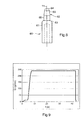
- FIG 8 illustrates more precisely an alternative embodiment of this type.
- This needle 60 of revolution along the axis 11, has, analogously to the needle 40 of Figures 2 to 5, an elongated cylindrical base 61, a nose 62 and, between the base 61 and the nose 62, a shoulder 63
- the base 61 and the shoulder 63 are identical to the base 41 and to the shoulder 43 of the needle 40.
- the nose 62 has, in addition to a spherical end 64, two sections: a conical section 65 whose small diameter connects without discontinuity to the spherical end 64 and a cylindrical section 66 which is adjacent to the shoulder 63 and which connects without discontinuity to the large diameter of the conical section 65.
- this type of stub needle is intended to be used in cooperation with a speed control cylinder and is mounted in a valve which is otherwise analogous to the valve 18 of FIGS. 2 to 5.
- the cylinder When the cylinder is of the speed control type, it allows, with the aid of a conventional associated control unit (not shown), to accurately control the linear speed of movement of the rod 51 and the needle 40 along of the axis 11. It is typically a hydraulic cylinder or pneumatic tire such as that marketed by SMC under the trademark SMC® and bearing the reference CDQ2B25-10D.
- Such a speed control of the needle will be used to control simple and frozen filling sequences, with constant opening and closing phases from one filling cycle to the other and fixed by the equipment. It is understood that in this case, only the speed (and not the position) of the needle being controlled, the nose 62 of the needle 60 acts, by analogy with the field of mechanics, in the manner of a "hydraulic cam" to realize the opening and closing phases that result from the shape of his profile.
- the shape of the needle nose illustrated in FIG. 8 is not limiting; it is of course possible to provide other nose shapes (for example with several conical sections of different slopes, or with a second-order continuous curve profile) generating a flow variation function of a type different from that illustrated in FIG. 9 and described below.
- the needle In use, the needle is actuated in translation by the jack, at constant speed or at least determined along the axis 11, so that its nose scrolls in the constriction 33 by engaging in or emerging from it gradually. Due to the non-uniform nature of the section of the nose along the axis axis 11 (function of "hydraulic cam"), it results from this displacement of the nose, a variation of the flow section and therefore flow corresponding to the nose profile.
- the three sections of the needle generate a filling sequence such as that shown in FIG. 9.
- a filling sequence such as that shown in FIG. 9.
- This sequence obtained with a feed pressure of 0.3 bar and a material having a viscosity of 200 cps, comprises three main stages: a flow increase step A ', a full flow fill step B' and a step descent in flow C '.
- the stage of The flow rate rise A 'and the rate descent step C' each divide into two phases, while the full flow rate step is monotonic, as detailed below.
- Step A ' rise in flow
- the filling sequence begins with the opening of the valve causing a rise in flow.
- the needle 60 is pulled by the jack from its initial closing position in which the shoulder 63 bears against the recess 34 of the first branch of the flow channel 30, towards its open position, at a speed constant of 1.25 mm / s. Due to the shape of the needle nose which exerts its function of "hydraulic cam", the opening is divided into three phases: a phase of first rise in flow A1 ', a start phase of filling low flow A2' and a phase of second rise in flow A3 '.
- Phase A1 ' first rise in flow
- the flow rate Dd ' is 10 g / min and the first flow rise phase lasts 2.5 s.
- the flow curve during this phase is almost linear.
- Other stages of flow rise curve may be provided for this phase, including a second order flow continuity with respect to time at the beginning and end of phase. It will be sufficient for this purpose to adjust the shape of the needle nose 42 in the vicinity of the shoulder 63 while providing for example another conical section.
- Phase A2 ' start of low flow filling
- the flow rate ceases to increase and reaches a plateau.
- the useful opening section (that is to say the section that imposes the flow rate) is then stable and exclusively defined by the cylindrical section. 66 of the nose 62 of the needle 60 in cooperation with the narrowing 33.
- the flow rate is then 10 g / min.
- the duration of this phase naturally related to the length of the section 66 and the speed of displacement of the needle 60, is in this case 2.5 s.
- Phase A3 ' second increase in flow
- the nominal flow rate D n ' is 240 g / min.
- the duration of this second rise in flow rate is 3 s.
- Step B ' full flow filling
- the needle stops in abutment when it reaches the maximum open position in which the end 64 of its nose is at the threshold of the narrowing 33.
- the flow rate is then maximum and corresponds to the nominal flow Dn 'above.
- Then begins the filling step at full flow, denoted B 'in Figure 9.
- the needle 60 is held stationary in its maximum open position.
- the opening section is then almost defined by the narrowing 33 alone.
- the flow rate is then 240 g / min.
- the duration of this phase, related to the parking time of the needle 60, is in this case 3.5 s.
- Step C ' flow descent
- the valve At the end of filling, the molding cavity being filled, the valve must be closed to cut the flow of material.
- the needle 60 is pushed back by the jack from its fully open position towards its closed position, at a constant speed of 20 mm / s which is therefore substantially greater than the speed of movement of the needle during the step of rising in flow A '.
- the closure of the valve, as the opening is divided into three phases: a phase of first descent in flow, a phase of end of filling low flow and a phase second descent in flow.
- step C can even be considered as almost monolithic with a very fast quasi-linear flow descent.
Landscapes
- Engineering & Computer Science (AREA)
- Mechanical Engineering (AREA)
- Manufacturing & Machinery (AREA)
- General Engineering & Computer Science (AREA)
- Health & Medical Sciences (AREA)
- Ophthalmology & Optometry (AREA)
- Casting Or Compression Moulding Of Plastics Or The Like (AREA)
- Moulds For Moulding Plastics Or The Like (AREA)
Claims (25)
- Schieberventil zum Befüllen einer Gussform mit einem organischen Material in flüssigem Zustand, umfassend:- einen Körper (25), in dem sich ein Strömungskanal (30) für das zu gießende Material befindet, mit einer Eingangsöffnung (31), einer Ausgangsöffnung (32) und, zwischen diesen zwei Öffnungen, einer Verengung (33), an die flussaufwärtsliegend eine einen Sitz bildende Verjüngung (34) angrenzt, und- einen Schieber (40), in dem Körper (25) bewegbar zwischen einer voll geöffneten Position und einer geschlossenen Position des Strömungskanals (30) angebracht, mit einem Zwischenbereich von Positionen variabler Öffnung zwischen diesen beiden Extrempositionen, wobei der Schieber (40) eine Schließschulter (43) aufweist, so ausgebildet, dass sie in der geschlossenen Position gegen die den Sitz formende Verjüngung (34) des Strömungskanals (30) im Körper (25) anliegt, so dass der Strömungskanal (34) gesperrt ist,dadurch gekennzeichnet, dass
der Schieber (40) vorspringend von der Schließschulter eine Öffnungs-Steuer-Nase (42) umfasst, die einen ungleichförmigen Schnitt aufweist und die so mit der Verengung (33) in Eingriff steht, dass sie mit dieser in jeder Zwischenposition des Schiebers (40) einen bestimmten Strömungsquerschnitt definiert. - Ventil gemäß Anspruch 1, bei welchem die Schließschulter (43) des Schiebers (40) stumpf/abgerundet ist.
- Ventil gemäß dem vorangehenden Anspruch, bei welchem die Verjüngung (34) des Strömungskanals (30) konisch ist.
- Ventil gemäß dem vorangehenden Anspruch, bei welchem die konische Verjüngung (34) einen Winkel am Scheitel zwischen 30 und 60 Grad aufweist.
- Ventil gemäß einem der vorangehenden Ansprüche, bei welchem die Nase (40) ein freies, abgerundetes Ende (46) aufweist.
- Ventil gemäß dem vorangehenden Anspruch, bei welchem das freie Ende der Nase (40) sphärisch ist.
- Ventil gemäß einem der vorangehenden Ansprüche, bei welchem in maximal geöffneter Position das freie Ende (46) der Nase (42) zumindest teilweise mit der Verengung (33) des Strömungskanals (30) in Eingriff steht.
- Ventil gemäß einem der vorangehenden Ansprüche, bei welchem die Nase (42) zumindest einen Abschnitt konischer Form aufweist.
- Ventil gemäß einem der vorangehenden Ansprüche, bei welchem die Nase mehrere Abschnitte bestimmter Form aufweist, ohne Unstetigkeit erster Ordnung zwischen den verschiedenen Abschnitten.
- Ventil gemäß Anspruch 8 oder 9, bei welchem die Nase zusätzlich zu ihrem konischen Abschnitt zumindest einen zylindrischen Abschnitt aufweist.
- Ventil gemäß einem der vorangehenden Ansprüche, bei welchem zumindest der Teil der Außenfläche des Schiebers (40), der in den Strömungskanal (30) eingebracht wird, in Polytetrafluorethylen ausgeführt ist.
- Ventil gemäß einem der vorangehenden Ansprüche, bei welchem die Innenfläche des Strömungskanals (30) des Körpers (25) aus Polytetrafluorethylen ist.
- Ventil gemäß einem der vorangehenden Ansprüche, bei welchem der Schieber (40) eine Rotations-Symmetrieachse (11) aufweist, und so in dem Körper (25) angeordnet ist, dass er entlang seiner Achse, die mit der Achse der Verengung (33) des Strömungskanals (30) des Körpers (25) zusammenfällt, verschiebbar ist.
- Ventil gemäß dem vorangehenden Anspruch, bei welchem eine ringförmige Abdichtung(44) aus einem Elastomer vom Typ Ethylen-Propylen-Dien zwischen dem Körper (25) und dem Schieber (40) angeordnet ist.
- Ventil gemäß einem der vorangehenden Ansprüche, bei welchem die Verengung (33) des Strömungskanals (30) mit einem Schnitt von konstanter Form und Dimension bis zu der Ausgangsöffnung (32) fortgeführt ist.
- Ventil gemäß einem der vorangehenden Ansprüche, bei welchem der Strömungskanal (30) eine L-Form aufweist, mit einem ersten Arm, rotationskörperartig bezüglich der Strömungsachse (11), wobei das freie Ende davon die Ausgangsöffnung (32) bildet, und einem zweiten Arm rotationskörperartig bezüglich einer Achse (35), senkrecht zur Strömungsachse (11).
- Ventil gemäß dem vorangehenden Anspruch, bei welchem der erste Arm des Kanals (30) abgestuft ist, mit einer weiten Basis (36) und am Ende, der Verengung (33), gefolgt von der Ausgangsöffnung (32), wobei die Basis (36) und die Verengung (33) zylindrisch sind und sich die Verjüngung (34) an die Verengung (33) und die Basis (36) mit abgerundeten Verbindungszonen anschließt.
- Verfahren zum Gießen eines optischen Elementes aus organischem Material in einen geeigneten Formhohlraum (6), umfassend eine Sequenz des Befüllens des Formhohlraum mit dem organischen Material in flüssigem Zustand und einen Schritt der Polymerisation des Materials in dem Formhohlraum, dadurch gekennzeichnet, dass die Sequenz des Befüllens des Formhohlraumes (6) mittels eines Ventils (15) gemäß einem der vorangehenden Ansprüche vorgenommen wird.
- Verfahren gemäß dem vorangehenden Anspruch, bei welchem die Position des Schiebers (40) gesteuert wird.
- Verfahren gemäß Anspruch 18, bei welchem die Geschwindigkeit des Schiebers (60) gesteuert wird.
- Verfahren gemäß dem vorangehenden Anspruch, bei welchem der Schieber mit verschiedenen Geschwindigkeiten zum Öffnen und zum Schließen bewegt wird.
- Verfahren gemäß dem vorangehenden Anspruch, bei welchem der Schieber beim Schließen mit einer höheren Geschwindigkeit bewegt wird als beim Öffnen.
- Verfahren gemäß einem der Ansprüche 18 bis 22, bei welchem die Sequenz des Befiillens die folgenden Schritte umfasst:- Steigern des Durchflusses (A), um von einem Durchfluss null auf einen nominalen Durchfluss von mehr als 40 g/min zu kommen,- befüllen mit vollem Durchfluss (B), unter Beibehaltung des nominalen Durchflusses (Dn),- verringern des Durchflusses (C), um von dem nominalen Durchfluss (Dn) auf einen Nulldurchfluss zurückzukehren,- dadurch gekennzeichnet, dass der Schritt des Steigerns des Durchflusses (A) aus mindestens zwei Phasen besteht:- Beginn des Auffüllens (A1) mit geringem Durchfluss, bis zu einer Befüllung des Formhohlraumes mit einer Materialhöhe von mindestens 2 mm über dem tiefsten Punkt des Formhohlraumes, wobei der Durchfluss im Verlauf dieser Phase bis zu einem maximalen Durchfluss des Befiillungsbeginns (Dd) von weniger als 20 g/min ansteigt, und danach- Hauptanstieg des Durchflusses (A2), um von dem Durchfluss des Befiillungsbeginns (Dd) auf den nominalen Durchfluss zu kommen.
- Verfahren gemäß einem der Ansprüche 18 bis 23, bei welchem das Material über eine Öffnung (9), befindlich im unteren Teil des Formhohlraumes, in den Formhohlraum (6) eingebracht wird.
- Verfahren gemäß einem der Ansprüche 18 bis 24, bei welchem die Polymerisation des Materials unmittelbar nach dem vollständigen Befüllen des Formhohlraumes initiiert wird.
Applications Claiming Priority (2)
| Application Number | Priority Date | Filing Date | Title |
|---|---|---|---|
| FR0300800 | 2003-01-24 | ||
| FR0300800A FR2850443B1 (fr) | 2003-01-24 | 2003-01-24 | Vanne a pointeau pour le remplissage d'un moule avec une matiere organique a l'etat liquide et procede de moulage d'un element optique au moyen d'une telle vanne |
Publications (2)
| Publication Number | Publication Date |
|---|---|
| EP1440780A1 EP1440780A1 (de) | 2004-07-28 |
| EP1440780B1 true EP1440780B1 (de) | 2007-03-07 |
Family
ID=32525003
Family Applications (1)
| Application Number | Title | Priority Date | Filing Date |
|---|---|---|---|
| EP04290124A Expired - Lifetime EP1440780B1 (de) | 2003-01-24 | 2004-01-16 | Nadelverschlussdüse zur Befüllung eines Werkzeuges mit einem flüssigen organischen Material sowie Verfahren zur Herstellung eines optischen Elements unter Verwendung einer solchen Düse |
Country Status (4)
| Country | Link |
|---|---|
| US (1) | US7367797B2 (de) |
| EP (1) | EP1440780B1 (de) |
| DE (1) | DE602004005084T2 (de) |
| FR (1) | FR2850443B1 (de) |
Families Citing this family (13)
| Publication number | Priority date | Publication date | Assignee | Title |
|---|---|---|---|---|
| FR2850319B1 (fr) * | 2003-01-24 | 2005-03-04 | Essilor Int | Procede de remplissage d'un moule avec une matiere organique a l'etat liquide en vue du moulage d'un element optique et procede de moulage incluant ce procede de remplissage |
| FR2890592B1 (fr) * | 2005-09-13 | 2007-11-30 | Essilor Int | Dispositif pour la realisation d'une lentille optique en matiere synthetique polymerisable. |
| JP2010240866A (ja) * | 2009-04-01 | 2010-10-28 | Seiko Epson Corp | プラスチックレンズ成形装置 |
| US20120136344A1 (en) | 2010-10-26 | 2012-05-31 | Medtronic Ardian Luxembourg S.A.R.L. | Neuromodulation cryotherapeutic devices and associated systems and methods |
| JP5621047B2 (ja) | 2010-11-23 | 2014-11-05 | シンベンティブ モールディング ソリューソンズ,インク. | 射出成形フロー制御装置および方法 |
| US10899056B2 (en) | 2011-11-23 | 2021-01-26 | Synventive Molding Solutions, Inc. | Non-coaxially mounted electric actuator and transmission |
| CN102700079A (zh) * | 2012-06-12 | 2012-10-03 | 深圳市精控机电有限公司 | 用于塑胶模具阀式热流道的针阀装置 |
| PT2885563T (pt) * | 2012-08-17 | 2017-03-15 | Uhde High Pressure Tech Gmbh | Válvula de alta pressão |
| DE102014114874A1 (de) * | 2013-11-22 | 2015-05-28 | Christopherus Bader | Verfahren zum Regeln der Füllung von zumindest einer Kavität |
| EP2889113A1 (de) * | 2013-12-27 | 2015-07-01 | ESSILOR INTERNATIONAL (Compagnie Générale d'Optique) | Maschine und Verfahren zum automatischen Füllen einer Form zum Formen einer ophthalmischen Linse |
| SG11201811717VA (en) * | 2016-08-30 | 2019-03-28 | Novartis Ag | Process for dispensing a contact lens forming fluid material |
| CN106738700A (zh) * | 2016-12-31 | 2017-05-31 | 中日龙电器制品(杭州)有限公司 | 两板模流道顶出装置 |
| MX2023008747A (es) | 2021-01-26 | 2023-10-10 | Ppg Ind Ohio Inc | Boquilla de fundicion multidireccional. |
Family Cites Families (15)
| Publication number | Priority date | Publication date | Assignee | Title |
|---|---|---|---|---|
| US50664A (en) * | 1865-10-24 | Geobge g | ||
| FR1309839A (fr) * | 1961-06-13 | 1962-11-23 | Bertin & Cie | Vanne équilibrée, notamment pour gaz chauds |
| US4190621A (en) | 1977-03-10 | 1980-02-26 | Martin Greshes | Method for molding optical plastic lenses of the standard and bifocal type |
| US4474356A (en) * | 1982-05-07 | 1984-10-02 | Baumann Hans D | Control valve with integral streamlined seating means |
| US5110514A (en) | 1989-05-01 | 1992-05-05 | Soane Technologies, Inc. | Controlled casting of a shrinkable material |
| JP2764891B2 (ja) * | 1994-07-08 | 1998-06-11 | 三井建設株式会社 | 揚重装置及び、該装置を用いた構築資材の運搬方法 |
| FR2727894A1 (fr) * | 1994-12-12 | 1996-06-14 | Essilor Int | Procede pour le remplissage d'un moule destine a l'obtention d'une lentille optique |
| FR2727895A1 (fr) | 1994-12-12 | 1996-06-14 | Essilor Int | Procede pour la realisation d'une lentille optique en matiere synthetique polymerisable et appareillage correspondant |
| EP0749821B1 (de) * | 1995-06-19 | 2003-03-05 | Siebolt Hettinga | Niederdruckverfahren zum Spritzgiessen eines Kunststoffgegestandes |
| US5902525A (en) | 1995-06-19 | 1999-05-11 | Hettinga; Siebolt | Method of molding a plastic article including injecting based upon a pressure-dominated control algorithm after detecting an indicia of a decrease in the surface area of the melt front |
| CA2175634C (en) * | 1996-05-02 | 2007-08-21 | Klaus Bauer | Injection molding valve member with head and neck portions |
| US6287107B1 (en) * | 1997-09-02 | 2001-09-11 | Synventive Molding Solutions, Inc. | Apparatus for proportionally controlling fluid delivery to a mold |
| US6328316B1 (en) * | 1999-01-12 | 2001-12-11 | Dupont Dow Elastomers, L.L.C. | Rubber seal for semi-dynamic applications |
| US20020161062A1 (en) * | 2001-11-06 | 2002-10-31 | Biermann Paul J. | Structure including a plurality of cells of cured resinous material, method of forming the structure and apparatus for forming the structure |
| WO2002032643A1 (en) * | 2000-10-19 | 2002-04-25 | Infiltrator Systems, Inc. | Gate flow diverter, mold for use therewith; and method for use thereof |
-
2003
- 2003-01-24 FR FR0300800A patent/FR2850443B1/fr not_active Expired - Fee Related
-
2004
- 2004-01-16 EP EP04290124A patent/EP1440780B1/de not_active Expired - Lifetime
- 2004-01-16 DE DE602004005084T patent/DE602004005084T2/de not_active Expired - Lifetime
- 2004-01-23 US US10/762,353 patent/US7367797B2/en not_active Expired - Fee Related
Also Published As
| Publication number | Publication date |
|---|---|
| DE602004005084T2 (de) | 2007-12-13 |
| DE602004005084D1 (de) | 2007-04-19 |
| FR2850443B1 (fr) | 2005-03-04 |
| US20040150125A1 (en) | 2004-08-05 |
| EP1440780A1 (de) | 2004-07-28 |
| FR2850443A1 (fr) | 2004-07-30 |
| US7367797B2 (en) | 2008-05-06 |
Similar Documents
| Publication | Publication Date | Title |
|---|---|---|
| EP1440780A1 (de) | Nadelverschlussdüse zur Befüllung eines Werkzeuges mit einem flüssigen organischen Material sowie Verfahren zur Herstellung eines optischen Elements unter Verwendung einer solchen Düse | |
| EP0715945B1 (de) | Verfahren zur Füllung einer Giessform für die Herstellung einer optischen Linse | |
| EP1440788B1 (de) | Verfahren zum Formen eines organischen optischen Elements | |
| EP0406068B1 (de) | Vorrichtung zur Herstellung von durchsichtigen Kunststoffschichten, welche ein eingefärbtes filtrierendes Band in der Masse aufweisen | |
| FR2520266A1 (fr) | Procede et dispositif de revetement de fibre optique | |
| FR2539203A1 (fr) | Valve a reglage prealable de debit, notamment pour installations de chauffage a eau chaude | |
| EP1841389B1 (de) | Verfahren zur Herstellung eines Reservoirs mit einer durch das Reservoir diffundierten aktiven Substanz und dessen Installation | |
| EP4433275A1 (de) | Verfahren zur herstellung eines mehrzelligen bauteils | |
| CA3015217A1 (fr) | Dispositif d'application de materiau abradable sur une surface d'un carter de turbomachine | |
| EP1446231B1 (de) | Austragkopf sowie flüssigkeitsspender mit einem solchen austragkopf | |
| FR3092567A1 (fr) | Bec de remplissage a depression | |
| WO2002042053A2 (fr) | Dispositif d'extrusion pour fabriquer un produit a base d'un melange caoutchouteux | |
| EP1762372B1 (de) | Vorrichtung zur Herstellung einer optischen Linse aus synthetischem Kunststoff | |
| EP2152493B1 (de) | Angelenkte Düse und Verfahren zum Auftragen eines Streifens aus viskoelastischem Material unter Verwendung der Düse | |
| EP2928675B1 (de) | Imprägnierungsvorrichtung, einheit zur herstellung eines hohlprofilabschnitts durch pultrusion mit solch einer vorrichtung und zugehöriges herstellungsverfahren | |
| FR2688440A1 (fr) | Procede et dispositif pour faire penetrer un materiau de revetement sous haute pression a l'interieur d'un moule. | |
| EP0629482B1 (de) | Umgossene Verglasung und Vorrichtung zu deren Herstellung | |
| FR2824136A1 (fr) | Procede de fabrication d'un compteur de liquide volumetrique du type a piston oscillant | |
| EP1731293B1 (de) | Giessform und Giessverfahren, insbesondere für Reaktionsspritzgiessverfahren, insbesondere von einem optischen Gegenstand aus Kunststoff | |
| EP1660236A1 (de) | Spritzkopf für fluidprodukt | |
| FR2856007A1 (fr) | Vanne et dispositif d'alimentation convenant au remplissage, avec une matiere polymerisable, d'une cavite de moulage | |
| EP0153539A1 (de) | Verfahren und Vorrichtung zum Beschichten der Stirnseiten eines Propergolkörpers | |
| WO2013131842A1 (fr) | Outil et procédé de réalisation d'un élément présentant une épaisseur réduite | |
| EP3368269A1 (de) | Vorrichtung zum extrudieren eines streifens aus elastomermaterial und verfahren zur herstellung einer hitzeschildabdeckung für einen schubkörper | |
| WO2015007906A1 (fr) | Dispositif d'extrusion de mélanges d'élastomères |
Legal Events
| Date | Code | Title | Description |
|---|---|---|---|
| PUAI | Public reference made under article 153(3) epc to a published international application that has entered the european phase |
Free format text: ORIGINAL CODE: 0009012 |
|
| AK | Designated contracting states |
Kind code of ref document: A1 Designated state(s): AT BE BG CH CY CZ DE DK EE ES FI FR GB GR HU IE IT LI LU MC NL PT RO SE SI SK TR |
|
| AX | Request for extension of the european patent |
Extension state: AL LT LV MK |
|
| 17P | Request for examination filed |
Effective date: 20041227 |
|
| AKX | Designation fees paid |
Designated state(s): DE FR GB |
|
| GRAP | Despatch of communication of intention to grant a patent |
Free format text: ORIGINAL CODE: EPIDOSNIGR1 |
|
| GRAS | Grant fee paid |
Free format text: ORIGINAL CODE: EPIDOSNIGR3 |
|
| GRAA | (expected) grant |
Free format text: ORIGINAL CODE: 0009210 |
|
| AK | Designated contracting states |
Kind code of ref document: B1 Designated state(s): DE FR GB |
|
| REG | Reference to a national code |
Ref country code: GB Ref legal event code: FG4D Free format text: NOT ENGLISH |
|
| REF | Corresponds to: |
Ref document number: 602004005084 Country of ref document: DE Date of ref document: 20070419 Kind code of ref document: P |
|
| GBT | Gb: translation of ep patent filed (gb section 77(6)(a)/1977) |
Effective date: 20070608 |
|
| PLBE | No opposition filed within time limit |
Free format text: ORIGINAL CODE: 0009261 |
|
| STAA | Information on the status of an ep patent application or granted ep patent |
Free format text: STATUS: NO OPPOSITION FILED WITHIN TIME LIMIT |
|
| 26N | No opposition filed |
Effective date: 20071210 |
|
| PGFP | Annual fee paid to national office [announced via postgrant information from national office to epo] |
Ref country code: GB Payment date: 20120116 Year of fee payment: 9 |
|
| GBPC | Gb: european patent ceased through non-payment of renewal fee |
Effective date: 20130116 |
|
| PG25 | Lapsed in a contracting state [announced via postgrant information from national office to epo] |
Ref country code: GB Free format text: LAPSE BECAUSE OF NON-PAYMENT OF DUE FEES Effective date: 20130116 |
|
| REG | Reference to a national code |
Ref country code: FR Ref legal event code: PLFP Year of fee payment: 13 |
|
| REG | Reference to a national code |
Ref country code: FR Ref legal event code: PLFP Year of fee payment: 14 |
|
| REG | Reference to a national code |
Ref country code: FR Ref legal event code: PLFP Year of fee payment: 15 |
|
| REG | Reference to a national code |
Ref country code: DE Ref legal event code: R082 Ref document number: 602004005084 Country of ref document: DE Representative=s name: 24IP LAW GROUP SONNENBERG FORTMANN, DE Ref country code: DE Ref legal event code: R081 Ref document number: 602004005084 Country of ref document: DE Owner name: ESSILOR INTERNATIONAL, FR Free format text: FORMER OWNER: ESSILOR INTERNATIONAL (COMPAGNIE GENERALE D'OPTIQUE), CHARENTON-LE-PONT, FR |
|
| REG | Reference to a national code |
Ref country code: FR Ref legal event code: TP Owner name: ESSILOR INTERNATIONAL, FR Effective date: 20180601 |
|
| PGFP | Annual fee paid to national office [announced via postgrant information from national office to epo] |
Ref country code: DE Payment date: 20190129 Year of fee payment: 16 Ref country code: FR Payment date: 20190125 Year of fee payment: 16 |
|
| REG | Reference to a national code |
Ref country code: DE Ref legal event code: R119 Ref document number: 602004005084 Country of ref document: DE |
|
| PG25 | Lapsed in a contracting state [announced via postgrant information from national office to epo] |
Ref country code: DE Free format text: LAPSE BECAUSE OF NON-PAYMENT OF DUE FEES Effective date: 20200801 Ref country code: FR Free format text: LAPSE BECAUSE OF NON-PAYMENT OF DUE FEES Effective date: 20200131 |