EP1440741A1 - Method of manufacturing hollow member - Google Patents
Method of manufacturing hollow member Download PDFInfo
- Publication number
- EP1440741A1 EP1440741A1 EP02775221A EP02775221A EP1440741A1 EP 1440741 A1 EP1440741 A1 EP 1440741A1 EP 02775221 A EP02775221 A EP 02775221A EP 02775221 A EP02775221 A EP 02775221A EP 1440741 A1 EP1440741 A1 EP 1440741A1
- Authority
- EP
- European Patent Office
- Prior art keywords
- tubular material
- longitudinal direction
- cross
- mold
- wall thickness
- Prior art date
- Legal status (The legal status is an assumption and is not a legal conclusion. Google has not performed a legal analysis and makes no representation as to the accuracy of the status listed.)
- Granted
Links
Images




Classifications
-
- B—PERFORMING OPERATIONS; TRANSPORTING
- B21—MECHANICAL METAL-WORKING WITHOUT ESSENTIALLY REMOVING MATERIAL; PUNCHING METAL
- B21K—MAKING FORGED OR PRESSED METAL PRODUCTS, e.g. HORSE-SHOES, RIVETS, BOLTS OR WHEELS
- B21K1/00—Making machine elements
- B21K1/06—Making machine elements axles or shafts
- B21K1/12—Making machine elements axles or shafts of specially-shaped cross-section
-
- B—PERFORMING OPERATIONS; TRANSPORTING
- B21—MECHANICAL METAL-WORKING WITHOUT ESSENTIALLY REMOVING MATERIAL; PUNCHING METAL
- B21C—MANUFACTURE OF METAL SHEETS, WIRE, RODS, TUBES, PROFILES OR LIKE SEMI-MANUFACTURED PRODUCTS OTHERWISE THAN BY ROLLING; AUXILIARY OPERATIONS USED IN CONNECTION WITH METAL-WORKING WITHOUT ESSENTIALLY REMOVING MATERIAL
- B21C37/00—Manufacture of metal sheets, rods, wire, tubes, profiles or like semi-manufactured products, not otherwise provided for; Manufacture of tubes of special shape
- B21C37/06—Manufacture of metal sheets, rods, wire, tubes, profiles or like semi-manufactured products, not otherwise provided for; Manufacture of tubes of special shape of tubes or metal hoses; Combined procedures for making tubes, e.g. for making multi-wall tubes
- B21C37/15—Making tubes of special shape; Making tube fittings
- B21C37/16—Making tubes with varying diameter in longitudinal direction
-
- B—PERFORMING OPERATIONS; TRANSPORTING
- B21—MECHANICAL METAL-WORKING WITHOUT ESSENTIALLY REMOVING MATERIAL; PUNCHING METAL
- B21D—WORKING OR PROCESSING OF SHEET METAL OR METAL TUBES, RODS OR PROFILES WITHOUT ESSENTIALLY REMOVING MATERIAL; PUNCHING METAL
- B21D53/00—Making other particular articles
- B21D53/88—Making other particular articles other parts for vehicles, e.g. cowlings, mudguards
Definitions
- the present invention relates to a process for producing a hollow member having a wall thickness, in a cross section orthogonal to the longitudinal direction, that varies in the longitudinal direction, and also to a process for producing a hollow member having a shape, in a cross section orthogonal to the longitudinal direction, that varies in the longitudinal direction.
- hollow metal members are employed as components of industrial equipment, transport equipment, etc. and, for example, they are widely employed as frame members such as body frames or door frames in automobiles.
- the hollow members have employed a lightweight material such as an aluminum material, and there is also a desire for the development of a tubular member having its wall thickness and cross-sectional shape freely controllable in the longitudinal direction and having surplus material cut out so as to give an optimum wall thickness distribution, and a hollow member having an optimum cross-sectional shape in the longitudinal direction.
- Japanese Patent Application Laid-open No. 10-230318 discloses a process for producing a hollow member having cross-sectional shape variation in the longitudinal direction by bulge forming a hollow material that has been extruded using a die and a mandrel in combination.
- Japanese Patent Application Laid-open No. 5-76950 and Japanese Patent No. 2874467 disclose processes for producing a hollow member in which, after a predetermined part of a tubular material having a uniform wall thickness is heated, the tubular material is compressed in the longitudinal direction so as to increase the thickness of the heated portion, thus giving a hollow member having a cross-sectional shape that varies in the longitudinal direction.
- the present invention has been achieved under the above-mentioned circumstances, and an object thereof is to provide a novel process for producing a hollow member, the process enabling a hollow member having an optimum wall thickness distribution in the longitudinal direction to be easily produced and also enabling a hollow member having a cross-sectional shape that varies in the longitudinal direction to be easily produced.
- Another object of the present invention is to provide a novel process for producing a hollow member, the process enabling the easy production of a hollow member having a desired wall thickness distribution in the longitudinal direction and a uniform circumference without constricted or expanded portions, or a hollow member having a cross-sectional shape that varies in the longitudinal direction.
- a process for producing a hollow member having a wall thickness, in a cross section orthogonal to the longitudinal direction, that varies in the longitudinal direction including a heating step of heating a tubular material so that the tubular material is given a temperature variation in the longitudinal direction, and a stretching step of axially stretching the tubular material that has been heated in the preceding step.
- a hollow member having a cross-sectional wall thickness that is variable in the longitudinal direction can be easily produced.
- a process for producing a hollow member having a shape, in a cross section orthogonal to the longitudinal direction, that varies in the longitudinal direction including a heating step of heating a tubular material so that the tubular material is given a temperature variation in the longitudinal direction, a stretching step of axially stretching the tubular material that has been heated in the preceding step, and a tube-expanding step of tube expanding an elongated tubular material, which has had its wall thickness in a cross section orthogonal to the longitudinal direction varied in the longitudinal direction in the preceding step, by setting the elongated tubular material within a cavity of a mold and applying an internal pressure to the elongated tubular material.
- a hollow member having a cross-sectional shape that varies in the longitudinal direction can be easily produced.
- a process for producing a hollow member having a wall thickness, in a cross section orthogonal to the longitudinal direction, that varies in the longitudinal direction including a heating step of heating a tubular material so that the tubular material is given a temperature variation in the longitudinal direction, and a stretching step of applying an internal pressure to the tubular material that has been heated in the preceding step and axially stretching the tubular material.
- a hollow member having a cross-sectional wall thickness that is variable in the longitudinal direction can be produced and, in particular, a hollow member having a substantially uniform circumference along its whole length without partial 'necking' can be produced precisely and easily by applying an internal pressure to the tubular material and axially stretching it.
- a process for producing a hollow member having a shape, in a cross section orthogonal to the longitudinal direction, that varies in the longitudinal direction including a heating step of heating a tubular material so that the tubular material is given a temperature variation in the longitudinal direction, a stretching step of applying an internal pressure to the tubular material (Pa) that has been heated in the preceding step and axially stretching the tubular material, and a tube-expanding step of tube expanding an elongated tubular material, which has had its wall thickness in a cross section orthogonal to the longitudinal direction varied in the longitudinal direction in the preceding step, by setting the elongated tubular material within a cavity of a mold and applying an internal pressure to the elongated tubular material.
- a hollow member having a cross-sectional shape that varies in the longitudinal direction can be produced and, in particular, a hollow member having a substantially uniform circumference along its whole length without partial 'necking' can be produced precisely and easily by applying an internal pressure to the tubular material and axially stretching it.
- the first embodiment is a case in which a hollow member having a substantially uniform cross-sectional wall thickness and an expanded tube portion is produced by variably controlling the cross-sectional wall thickness in the longitudinal direction of a tubular material Pa, which is made of an aluminum alloy and has a uniform cross-sectional wall thickness and a uniform diameter in the longitudinal direction, and then carrying out tube expansion (bulge forming), and this process specifically includes
- the tubular material Pa which has a uniform cross-sectional wall thickness and a uniform cross-sectional shape in the longitudinal direction and is made of an aluminum alloy, is heated in part in the longitudinal direction using heating means such as, for example, ohmic heating means HE. That is, electrically connected to opposite end portions of the tubular material Pa are a + electrode 30 and a - electrode 31 of the ohmic heating means HE, and disposed on the outer peripheral face of a middle portion of the tubular material Pa is current bypass means BP.
- heating means such as, for example, ohmic heating means HE. That is, electrically connected to opposite end portions of the tubular material Pa are a + electrode 30 and a - electrode 31 of the ohmic heating means HE, and disposed on the outer peripheral face of a middle portion of the tubular material Pa is current bypass means BP.
- This current bypass means BP is formed by electrically connecting two low resistance conductors (e.g., copper conductors) 32 and 33 having lower electrical resistance than that of the aluminum alloy to the longitudinally middle portion of the tubular material Pa so as to encircle it, the two conductors 32 and 33 having a spacing therebetween in the longitudinal direction, and connecting the low resistance conductors 32 and 33 to each other via a lead 34.
- two low resistance conductors e.g., copper conductors
- the tubular material Pa is provided with stretching means PL for axially stretching the tubular material Pa.
- This stretching means PL is formed from a fixed member 35 fixed to one end of the tubular material Pa, a movable member 36 fixed to the other end thereof, and a tensile actuator, that is, a tensile cylinder 37, connected to the movable member 36, and the tubular material Pa is stretched longitudinally in accordance with contraction of the tensile cylinder 37.
- the ohmic heating means HE When the ohmic heating means HE is energized, current flows through the tubular material Pa, the bypass means BP, and then again through the tubular material Pa. That is, since the two low resistance conductors 32 and 33 have a lower electrical resistance than that of the tubular material Pa, which is made of an aluminum alloy, as shown by arrow a in FIG. 3A the current flows through the tubular material Pa while bypassing the hollow portion N of the tubular material Pa, the hollow portion N corresponding to a section between the two low resistance conductors 32 and 33. The portions S on longitudinally opposite sides of the tubular material Pa are therefore heated, and compared with the middle portion N the amount of heat generated therein is relatively large.
- the stretching means PL for the tubular material Pa does not operate.
- the two low resistance conductors 32 and 33 of the current bypass means BP are detached from the tubular material Pa while continuing to operate the ohmic heating means HE.
- the + electrode 30 and the electrode 31 of the ohmic heating means HE are thereby electrically connected through the whole length of the tubular material Pa, current flows through the tubular material Pa as shown by arrow b in FIG. 3B, and the tubular material Pa is ohmically heated along its whole length.
- the left and right portions S on opposite sides of the tubular material Pa are therefore heated to a high temperature, for example, the recrystallization temperature (500°C) of the tubular material Pa or higher, whereas the middle portion N of the tubular material Pa is heated to a lower temperature.
- a high temperature for example, the recrystallization temperature (500°C) of the tubular material Pa or higher
- the middle portion N of the tubular material Pa is heated to a lower temperature.
- the left and right portions S on opposite sides and the middle portion N of the tubular material Pa are heated to a state where they have a predetermined temperature difference, and operating the stretching means PL applies a predetermined tension to the tubular material Pa in the axial direction.
- the tubular material Pa is thereby elongated in the axial direction; since the left and right portions S at opposite ends, which have been heated to a high temperature, have a small resistance to deformation, they elongate quickly and thus have a large amount of elongation, whereas since the middle portion N, which has been heated to a lower temperature, has higher resistance to deformation, it elongates slowly and thus has a small amount of elongation.
- the cross-sectional wall thickness in the hollow portion N of the tubular material Pb thus elongated in the axial direction is large, that is, 1.25t, and the cross-sectional wall thickness of the left and right portions S on opposite sides, that is, t, is smaller than that of the hollow portion N.
- the cross-sectional wall thickness of the elongated tubular material Pb is thus variably controlled in the axial direction.
- the elongated tubular material Pb which has been elongated in the axial direction in the preceding step, is transferred to a tube-expanding (bulge-forming) device by appropriate transfer means.
- a mold M of the tube-expanding (bulge-forming) device comprises a fixed mold, that is, a lower mold 2, fixedly provided on a base 1, and a mobile mold, that is, an upper mold 3, which faces the fixed mold.
- Raise/lower cylinders 4 are connected to the top of the mold M, and the upper mold 3 is operated so as to be raised and lowered by expansion/contraction of the raise/lower cylinders 4.
- the mold M is a tube-expanding mold and is for subjecting the elongated tubular material Pb, which has been axially elongated in the above step and maintained in a heated state (about 500°C), to hot tube expansion (hot bulge forming) at the recrystallization temperature thereof or higher.
- This mold M is heated to about 500°C by heating means, which is not illustrated.
- a lower mold molding surface 2m Formed on the upper face of the lower mold 2 is a lower mold molding surface 2m, with which the lower half of the elongated tubular material Pb is molded.
- an upper mold molding surface 3m Formed on the lower face of the upper mold 3 is an upper mold molding surface 3m, with which the upper half of the elongated tubular material Pb is molded.
- a cavity 5 is formed by the molding surfaces 2m and 3m when the mold M is closed.
- holding means H Provided on opposite sides on the left and right of the mold M is holding means H for fixing the opposite end portions of the elongated tubular material Pb.
- the holding means H comprises left and right holders 6 and 7 on the left and right of the mold M; these holders 6 and 7 can be moved forward and backward relative to the mold M, and are controlled by the operation of actuators 10 and 11 so as to move along guides 8 and 9 provided on the base 1.
- actuators 10 and 11 By moving the left and right holders 6 and 7 forward, the opposite end portions of the elongated tubular material Pb are fitted into and fixed to support holes 6a and 7a of the left and right holders 6 and 7.
- pushing means Pu for axially pushing the elongated tubular material Pb set in the mold M.
- This pushing means PU has left and right pressure cylinders 12 and 13. Pressing members 16 and 17 secured to the extremities of rod portions 12r and 13r of these pressure cylinders 12 and 13 are fitted within the support holes 6a and 6b of the left and right holders 6 and 7 so as to be able to move forward and backward.
- O-rings 19 and 20 as sealing means S are provided respectively between the left and right pressing members 16 and 17 and the support holes 6a and 7a, and between the support holes 6a and 7a and outer peripheral faces of the opposite end portions of the elongated tubular material Pb. These O-rings 19 and 20 can provide a fluid tight seal between the elongated tubular material Pb, the holders 6 and 7, and the pressing members 16 and 17 when the pressing members 16 and 17 are engaged with the elongated tubular material Pb.
- compressed air supply means A for pressurizing the interior of the elongated tubular material Pb.
- This compressed air supply means A is arranged so that compressed air is supplied under pressure from a compressed air supply source 22 to a hermetically sealed hollow portion of the elongated tubular material Pb via a compressed air circuit 23 and an air introduction route 24 bored in the pressing members 16 and 17.
- the elongated tubular material Pb which has been elongated in the preceding step and is still in a heated state (about 500°C) is placed and set within the mold M, which has been heated similarly to about 500°C, and the first mold M1 is clamped by means of the operation of a mold clamping cylinder, that is, the raise/lower cylinder 4.
- the elongated tubular material Pb after tube expansion is taken out of the mold M by opening the mold M after the left and right holders 6 and 7 are moved backward, and a tube-expanded tube (bulge-formed tube) Pc is obtained as shown in FIG. 2 (c).
- this tube-expanded tube Pc is formed in a shape having an enlarged portion comprising the hollow portion N, left and right tapered and truncated cone portions comprising the left and right portions S on opposite sides, which extend leftward and rightward from the enlarged portion, and left and right end portions E, which extend from the cone portions and have not been subjected to tube expansion (bulge forming), and the left and right end portions E are cut off to give a final molding, that is, a hollow member P (see FIG. 1).
- the cross-sectional wall thickness of the left and right portions S on opposite sides is t
- the cross-sectional wall thickness of the middle portion N is 1.25t, which is thicker than t.
- the middle portion N thereof is radially elongated to a larger extent than that to which the left and right portions S on opposite sides are elongated, thus forming an enlarged diameter portion, and the tube Pc after tube expansion therefore has a substantially uniform wall thickness t along the whole length thereof as shown in FIG. 2 (c).
- the final molding after tube expansion, from which the left and right end portions E have been cut off, that is, the hollow member P is a tube-expanded tube Pc having a substantially uniform cross-sectional wall thickness t along its whole length even though the cross-sectional shape has been changed by tube expansion.
- the defect of the conventional tube-expanding (bulge-forming) method that is, the cross section of the bulge-formed portion becoming thin, can be eliminated.
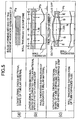
- FIG. 5 is a diagram showing production steps for producing a hollow member from a tubular material, and a tubular material Pa prior to processing has a uniform wall thickness of 1.5t along its whole length in the longitudinal direction as shown in FIG. 5 (a).
- the tubular material Pa is subjected to a partial ohmic heating step and an overall ohmic heating step, which are the same as those in the first embodiment, and by controlling the partial heating temperature in the longitudinal direction and controlling the tensile force in a stretch-forming step, an elongated tubular material Pb having a wall thickness of 1.5t for its middle portion N and a wall thickness of t for its left and right portions S on opposite sides can be obtained.
- the elongated tubular material Pb is subjected to (4) tube expansion (bulge forming) in the same manner as in the first embodiment, and a tube-expanded tube Pc can be obtained, the tube Pc having a middle portion N formed by tube expansion so as to have an enlarged diameter and having a cross-sectional wall thickness of 1.25t, which is thicker than its left and right portions S on opposite sides thereof, which have a wall thickness of t.
- a hollow member having surplus material cut out can be easily produced by variably controlling the cross-sectional wall thickness in the longitudinal direction and, furthermore, a hollow member having a cross-sectional shape that varies in the longitudinal direction can be simply and easily produced by variably controlling the cross-sectional wall thickness in the longitudinal direction.
- a hollow member having a cross-sectional wall thickness that is variable in the longitudinal direction can be easily produced.
- a hollow member having a cross-sectional shape that varies in the longitudinal direction can be easily produced.
- a third embodiment of the present invention is explained with reference to FIG. 5 to 10.
- the third embodiment is a case in which a hollow member having a substantially uniform cross-sectional wall thickness and an expanded tube portion is produced by variably controlling the cross-sectional wall thickness in the longitudinal direction of a tubular material Pa, which is made of an aluminum alloy and has a uniform cross-sectional wall thickness and a uniform diameter in the longitudinal direction, and then carrying out tube expansion (bulge forming), and this process specifically includes
- a tubular material Pa which has a uniform cross-sectional wall thickness and a uniform cross-sectional shape in the longitudinal direction and is made of an aluminum alloy, is heated in part in the longitudinal direction using heating means such as, for example, ohmic heating means HE. That is, electrically connected to opposite end portions of the tubular material Pa are a + electrode 30 and a - electrode 31 of the ohmic heating means HE, and disposed on the outer peripheral face of a middle portion of the tubular material Pa is current bypass means BP.
- heating means such as, for example, ohmic heating means HE. That is, electrically connected to opposite end portions of the tubular material Pa are a + electrode 30 and a - electrode 31 of the ohmic heating means HE, and disposed on the outer peripheral face of a middle portion of the tubular material Pa is current bypass means BP.
- This current bypass means BP is formed by electrically connecting two low resistance conductors (e.g., copper conductors) 32 and 33 having lower electrical resistance than that of the aluminum alloy to the longitudinally middle portion of the tubular material Pa so as to encircle it, the two conductors 32 and 33 having a spacing therebetween in the longitudinal direction, and connecting the low resistance conductors 32 and 33 to each other via a lead 34.
- two low resistance conductors e.g., copper conductors
- the tubular material Pa is provided with seals 36 and 37 for sealing opposite open ends on the left and right thereof and, furthermore, on opposite sides thereof in the axial direction with internal pressurizing means PR for applying an internal pressure to the tubular material Pa in the subsequent internal pressurizing and stretch-forming step and stretching means PL for stretching the tubular material Pa in the axial direction.
- the internal pressurizing means PR comprises an internal pressurizing source 50 for supplying pressurized air into the interior of the tubular material Pa, and a pressurizing circuit 51 for providing a connection between the internal pressurizing source 50 and the interior of the tubular material Pa.
- the pressurized air is supplied under pressure from the pressurizing circuit 51 to the interior of the tubular material Pa via one of the seals 35.
- this stretching means PL is formed from a tensile actuator, that is, a tensile cylinder 37, connected to the seal 36 provided at the other end of the tubular material Pa, and the tubular material Pa is stretched longitudinally in accordance with operation of the tensile cylinder 37.
- the ohmic heating means HE When the ohmic heating means HE is energized, current flows through the tubular material Pa, the bypass means BP, and then again through the tubular material Pa. That is, since the two low resistance conductors 32 and 33 have a lower electrical resistance than that of the tubular material Pa, which is made of an aluminum alloy, as shown by arrow a in FIG. 8A the current flows through the tubular material Pa while bypassing the hollow portion N of the tubular material Pa, the hollow portion N corresponding to a section between the two low resistance conductors 32 and 33. The portions S on longitudinally opposite sides of the tubular material Pa are therefore heated, and compared with the middle portion N the amount of heat generated therein is relatively large.
- the two low resistance conductors 32 and 33 of the current bypass means BP are detached from the tubular material Pa while continuing to operate the ohmic heating means HE.
- the + electrode 30 and the - electrode 31 of the ohmic heating means HE are thereby electrically connected through the whole length of the tubular material Pa, current flows through the tubular material Pa as shown by arrow b in FIG. 8B, and the tubular material Pa is ohmically heated along its whole length.
- the left and right portions S on opposite sides of the tubular material Pa are therefore heated to a high temperature, for example, the recrystallization temperature (500°C) of the tubular material Pa or higher, whereas the middle portion N of the tubular material Pa is heated to a lower temperature.
- a high temperature for example, the recrystallization temperature (500°C) of the tubular material Pa or higher
- the middle portion N of the tubular material Pa is heated to a lower temperature.
- the left and right portions S on opposite sides and the middle portion N of the tubular material Pa are heated to a state where they have a predetermined temperature difference, and the internal pressurizing means PR is operated so as to supply pressurized air to the interior of the tubular material Pa and apply a predetermined internal pressure to the interior of the tubular material Pa while operating the stretching means PL so as to apply a predetermined tension to the tubular material Pa in the axial direction.
- the tubular material Pa is thereby elongated in the axial direction with a predetermined internal pressure being applied to the interior thereof.
- the left and right portions S at opposite ends which have been heated to a high temperature, have a low resistance to deformation, they elongate quickly and thus have a large amount of elongation, whereas since the middle portion N, which has been heated to a lower temperature, has higher resistance to deformation, it elongates slowly and thus has a small amount of elongation.
- the interior of the tubular material Pa is exposed to a predetermined internal pressure because of the pressurized air supplied from the internal pressurizing means PR, even though there is stretching in the axial direction, no 'necking' occurs in the axial direction, and the circumference of the tubular material Pa is maintained substantially uniform along its whole length.
- the cross-sectional wall thickness in the hollow portion N of the elongated tubular material Pb thus elongated in the axial direction is large, that is, 1.25t, and the cross-sectional wall thickness of the left and right portions S on opposite sides, that is, t, is smaller than that of the hollow portion N.
- the cross-sectional wall thickness is thus variably controlled, and an elongated tubular material Pb having no 'necking' and a substantially uniform circumference along its whole length can be obtained.
- the elongated tubular material Pb which has been elongated in the axial direction in the preceding step and has a substantially uniform circumference, is transferred to a tube-expanding (bulge-forming) device by appropriate transfer means.
- a mold M of the tube-expanding (bulge-forming) device comprises a fixed mold, that is, a lower mold 2, fixedly provided on a base 1 and a mobile mold, that is, an upper mold 3, which faces the fixed mold.
- Raise/lower cylinders 4 are connected to the top of the mold M, and the upper mold 3 is operated so as to be raised and lowered by expansion/contraction of the raise/lower cylinders 4.
- the mold M is a tube-expanding mold and is for subjecting the elongated tubular material Pb, which has been axially elongated in the above step and maintained in a heated state (about 500°C), to hot tube expansion (hot bulge forming) at the recrystallization temperature thereof or higher.
- This mold M is heated to about 500°C by heating means, which is not illustrated.
- a lower mold molding surface 2m Formed on the upper face of the lower mold 2 is a lower mold molding surface 2m, with which the lower half of the elongated tubular material Pb is molded.
- an upper mold molding surface 3m Formed on the lower face of the upper mold 3 is an upper mold molding surface 3m, with which the upper half of the elongated tubular material Pb is molded.
- a cavity 5 is formed by the molding surfaces 2m and 3m when the mold M is closed.
- holding means H Provided on opposite sides on the left and right of the mold M is holding means H for fixing the opposite end portions of the elongated tubular material Pb.
- the holding means H comprises left and right holders 6 and 7 on the left and right of the mold M; these holders 6 and 7 can be moved forward and backward relative to the mold M, and are controlled by the operation of actuators 10 and 11 so as to move along guides 8 and 9 provided on the base 1.
- actuators 10 and 11 By moving the left and right holders 6 and 7 forward, the opposite end portions of the elongated tubular material Pb are fitted into and fixed to support holes 6a and 7a of the left and right holders 6 and 7.
- pushing means Pu for axially pushing the elongated tubular material Pb set in the mold M.
- This pushing means PU has left and right pressure cylinders 12 and 13. Pressing members 16 and 17 secured to the extremities of rod portions 12r and 13r of these pressure cylinders 12 and 13 are fitted within the support holes 6a and 6b of the left and right holders 6 and 7 so as to be able to move forward and backward.
- O-rings 19 and 20 as sealing means S are provided respectively between the left and right pressing members 16 and 17 and the support holes 6a and 7a, and between the support holes 6a and 7a and outer peripheral faces of the opposite end portions of the elongated tubular material Pb. These O-rings 19 and 20 can provide a fluid tight seal between the elongated tubular material Pb, the holders 6 and 7, and the pressing members 16 and 17 when the pressing members 16 and 17 are engaged with the elongated tubular material Pb.
- compressed air supply means A for pressurizing the interior of the elongated tubular material Pb.
- This compressed air supply means A is arranged so that compressed air is supplied under pressure from a compressed air supply source 22 to a hermetically sealed hollow portion of the elongated tubular material Pb via a compressed air circuit 23 and an air introduction route 24 bored in the pressing members 16 and 17.
- the elongated tubular material Pb which has been elongated in the preceding step and is still in a heated state (about 500°C), is placed and set within the mold M, which has been heated similarly to about 500°C, and the mold M is clamped by means of the operation of a mold clamping cylinder, that is, the raise/lower cylinder 4.
- a mold clamping cylinder that is, the raise/lower cylinder 4.
- the elongated tubular material Pb after tube expansion is taken out of the mold M by opening the mold M after the left and right holders 6 and 7 are moved backward, and a tube-expanded tube (bulge-formed tube) Pc is obtained as shown in FIG. 7 (c).
- this tube-expanded tube Pc is formed in a shape having an enlarged portion comprising the hollow portion N, left and right tapered and truncated cone portions comprising the left and right portions S on opposite sides, which extend leftward and rightward from the enlarged portion, and left and right end portions E, which extend from the cone portions and have not been subjected to tube expansion (bulge forming), and the left and right end portions E are cut off to give a final molding, that is, a hollow member P (see FIG. 6).
- the cross-sectional wall thickness of the left and right portions S on opposite sides is t
- the cross-sectional wall thickness of the middle portion N is 1.25t, which is thicker than t and, moreover, the outer peripheral face thereof has no 'necking' along its whole length and has a uniform circumference.
- the middle portion N thereof is radially elongated to a larger extent than that to which the left and right portions S on opposite sides are elongated, thus forming an enlarged diameter portion, and the tube Pc after tube expansion therefore has a substantially uniform wall thickness t along the whole length thereof.
- the final molding after tube expansion, from which the left and right end portions E have been cut off, that is, the hollow member P is a tube-expanded tube Pc having a substantially uniform cross-sectional wall thickness t along its whole length even though the cross-sectional shape has been changed by tube expansion.
- the defect of the conventional tube-expanding (bulge-forming) method that is, the cross section of the bulge-formed portion becoming thin, can be eliminated.
- FIG. 11 is a diagram showing production steps for producing a hollow member from a tubular material, and a tubular material Pa prior to processing has a uniform wall thickness of 1.5t along its whole length in the longitudinal direction as shown in FIG. 11 (a).
- the tubular material Pa is subjected to a partial ohmic heating step and an overall ohmic heating step, which are the same as those in the third embodiment, and by controlling the partial heating temperature in the longitudinal direction, and controlling the internal pressure and the tensile force in an internal pressurizing and stretch-forming step, an elongated tubular material Pb having a uniform circumference without 'necking' and having a wall thickness of 1.5t for its middle portion N and a wall thickness of t for its left and right portions S on opposite sides can be obtained.
- the elongated tubular material Pb is subjected to (4) tube expansion (bulge forming) in the same manner as in the third embodiment, and a tube-expanded tube Pc can be obtained, the tube Pc having a middle portion N formed by tube expansion so as to have an enlarged diameter and having a cross-sectional wall thickness of 1.25t, which is thicker than the left and right portions S on opposite sides thereof, which have a wall thickness of t.
- a fifth embodiment of the present invention is now explained with reference to FIG. 12.
- FIG. 12 is a cross-sectional view of an internal pressurizing and stretch-forming device for a tubular material.
- a partial heating step (1) for a tubular material Pa an overall ohmic heating step (2) for the tubular material Pa, and a tube-expanding (bulge-forming) step (4) for the elongated tubular material Pb of the above third embodiment are the same as in the first embodiment, but specific arrangements of an internal pressurizing and stretch-forming step (3) for the tubular material Pa are different from those of the third embodiment. That is, in accordance with this fifth embodiment, as shown in FIG.
- the axial stretch-forming step of the heated tubular material Pa with internal pressure applied thereto is carried out within a mold M1; the occurrence of partial 'necking' on the outer peripheral face during stretching of the tubular material Pa can be prevented more reliably and, moreover, the circumference thereof can be made uniform along its whole length.
- the specific arrangements thereof are explained below with reference to FIG. 12.
- the tubular material Pa which has been heated with a temperature variation in the longitudinal direction via the preceding heating step (its left and right portions S on opposite sides are at a recrystallization temperature (500°C or more), and its middle portion N is at lower temperature than the above), is set in a mold M1 for internal pressurizing and stretching.
- This mold M1 comprises a lower mold 55 fixed on top of a base 53, and an upper mold 54 that can be raised and lowered relative to the lower mold 55, the upper mold 54 being connected to raise/lower cylinders 56 so as to be able to be raised and lowered.
- the mold M1 is maintained at an appropriate temperature so that the tubular material Pa, which is in a partially heated state, is maintained in that heated state.
- a seal 57 for sealing said one open end
- the other open end of the tubular material Pa (righthand end portion in FIG. 7) is another seal 58 for sealing said other open end.
- Said other seal 58 is connected to a tensile cylinder 37 of stretching means PL. Furthermore, disposed in said one end portion of the mold M1 is internal pressurizing means PR for pressurizing the interior of the tubular material Pa to a predetermined pressure.
- This internal pressurizing means PR is arranged so that pressurized air from an internal pressurizing source 50 is supplied under pressure to the interior of the tubular material Pa via a pressurizing circuit 51.
- the tubular material Pa set within the mold M1 has its internal pressure maintained at a predetermined pressure as a result of the supply of pressurized air from the internal pressurizing means PR and is subjected to a predetermined tension in the axial direction by operation of the tensile cylinder 37 of the stretching means PL.
- the elongated tubular material Pb after stretching is subjected to the tube-expanding (bulge-forming) step of the first embodiment, and a tube-expanded product having a variable shape in a cross section orthogonal to the longitudinal direction can thus be obtained.
- a hollow member having a cross-sectional wall thickness that is variable in the longitudinal direction or having a cross-sectional shape that varies in the longitudinal direction can be produced and, in particular, an elongated tubular member having no partial 'necking' and having a substantially uniform circumference along its whole length can be precisely and easily produced by stretching a tubular material in the axial direction with an internal pressure applied thereto.
- the above-mentioned embodiments describe cases in which the forming process of the present invention is applied to a hollow member made of an aluminum alloy, but this can of course be applied to a hollow member that is made of another metal, and in this case the heating temperatures for the tubular material and the mold are controlled according to the material of the tubular member, etc.
- air is used as a compressible fluid for applying internal pressure to the tubular material, but another fluid can be used.
Landscapes
- Engineering & Computer Science (AREA)
- Mechanical Engineering (AREA)
- Shaping Metal By Deep-Drawing, Or The Like (AREA)
- Body Structure For Vehicles (AREA)
- Shaping Of Tube Ends By Bending Or Straightening (AREA)
Abstract
Description
Claims (4)
- A process for producing a hollow member having a wall thickness, in a cross section orthogonal to the longitudinal direction, that varies in the longitudinal direction, the process comprising:a heating step of heating a tubular material (Pa) so that the tubular material (Pa) is given a temperature variation in the longitudinal direction; anda stretching step of axially stretching the tubular material (Pa) that has been heated in the preceding step.
- A process for producing a hollow member having a shape, in a cross section orthogonal to the longitudinal direction, that varies in the longitudinal direction, the process comprising:a heating step of heating a tubular material (Pa) so that the tubular material (Pa) is given a temperature variation in the longitudinal direction;a stretching step of axially stretching the tubular material (Pa) that has been heated in the preceding step; anda tube-expanding step of tube expanding an elongated tubular material (Pb), which has had its wall thickness in a cross section orthogonal to the longitudinal direction varied in the longitudinal direction in the preceding step, by setting the elongated tubular material (Pb) within a cavity (5) of a mold (M) and applying an internal pressure to the elongated tubular material (Pb).
- A process for producing a hollow member having a wall thickness, in a cross section orthogonal to the longitudinal direction, that varies in the longitudinal direction, the process comprising:a heating step of heating a tubular material (Pa) so that the tubular material (Pa) is given a temperature variation in the longitudinal direction; anda stretching step of applying an internal pressure to the tubular material (Pa) that has been heated in the preceding step and axially stretching the tubular material (Pa).
- A process for producing a hollow member having a shape, in a cross section orthogonal to the longitudinal direction, that varies in the longitudinal direction, the process comprising:a heating step of heating a tubular material (Pa) so that the tubular material (Pa) is given a temperature variation in the longitudinal direction;a stretching step of applying an internal pressure to the tubular material (Pa) that has been heated in the preceding step and axially stretching the tubular material (Pa); anda tube-expanding step of tube expanding an elongated tubular material (Pb), which has had its wall thickness in a cross section orthogonal to the longitudinal direction varied in the longitudinal direction in the preceding step, by setting the elongated tubular material (Pb) within a cavity (5) of a mold (M) and applying an internal pressure to the elongated tubular material (Pb).
Applications Claiming Priority (3)
| Application Number | Priority Date | Filing Date | Title |
|---|---|---|---|
| JP2001294347A JP4944322B2 (en) | 2001-09-26 | 2001-09-26 | Method for manufacturing hollow member |
| JP2001294347 | 2001-09-26 | ||
| PCT/JP2002/009716 WO2003028914A1 (en) | 2001-09-26 | 2002-09-20 | Method of manufacturing hollow member |
Publications (3)
| Publication Number | Publication Date |
|---|---|
| EP1440741A1 true EP1440741A1 (en) | 2004-07-28 |
| EP1440741A4 EP1440741A4 (en) | 2007-03-21 |
| EP1440741B1 EP1440741B1 (en) | 2008-05-21 |
Family
ID=19115971
Family Applications (1)
| Application Number | Title | Priority Date | Filing Date |
|---|---|---|---|
| EP02775221A Expired - Lifetime EP1440741B1 (en) | 2001-09-26 | 2002-09-20 | Method of manufacturing hollow member |
Country Status (6)
| Country | Link |
|---|---|
| US (1) | US7175799B2 (en) |
| EP (1) | EP1440741B1 (en) |
| JP (1) | JP4944322B2 (en) |
| CN (1) | CN1261248C (en) |
| CA (1) | CA2461208C (en) |
| WO (1) | WO2003028914A1 (en) |
Cited By (1)
| Publication number | Priority date | Publication date | Assignee | Title |
|---|---|---|---|---|
| DE102006028873A1 (en) * | 2006-06-21 | 2007-12-27 | Benteler Automobiltechnik Gmbh | Production of a metal tube with different wall thicknesses comprises locally heating the tube having a starting wall thickness which is the same over its length in the longitudinal regions to be changed and loading with a traction force |
Families Citing this family (16)
| Publication number | Priority date | Publication date | Assignee | Title |
|---|---|---|---|---|
| JP5380189B2 (en) * | 2009-07-21 | 2014-01-08 | 本田技研工業株式会社 | Hot bulge forming equipment |
| US20110166370A1 (en) | 2010-01-12 | 2011-07-07 | Charles Winston Saunders | Scattered Branched-Chain Fatty Acids And Biological Production Thereof |
| KR101287135B1 (en) | 2012-05-09 | 2013-07-17 | 포항공과대학교 산학협력단 | Extrusion apparatus and method for metallic material |
| CN103736811B (en) * | 2014-01-23 | 2016-04-27 | 哈尔滨工业大学 | Adopt the method axially not waiting the wall thickness variable diameters pipe fittings such as wall thickness pipe shaping |
| US9493726B2 (en) | 2014-09-08 | 2016-11-15 | The Procter & Gamble Company | Detergent compositions containing a predominantly C15 branched alkyl alkoxylated surfactant |
| CA2958305A1 (en) | 2014-09-08 | 2016-03-17 | The Procter & Gamble Company | Detergent compositions containing a branched surfactant |
| CN104438541A (en) * | 2014-12-08 | 2015-03-25 | 无锡朗贤汽车组件研发中心有限公司 | Inflatable hot forming tube-producing equipment |
| CN105728616B (en) * | 2014-12-10 | 2018-05-29 | 陕西宏远航空锻造有限责任公司 | A kind of free forging method of the trapezoidal forging of central hollow |
| KR102345212B1 (en) * | 2015-08-27 | 2021-12-30 | 스미도모쥬기가이고교 가부시키가이샤 | Molding device and molding method |
| FR3062586B1 (en) * | 2017-02-08 | 2020-02-28 | Adm28 S.Ar.L | ELECTROHYDROFORMING DEVICE |
| JP2018167284A (en) * | 2017-03-29 | 2018-11-01 | 住友重機械工業株式会社 | Metal body and current heating method |
| CN108655249A (en) * | 2017-03-30 | 2018-10-16 | 宝山钢铁股份有限公司 | A kind of hydraulic expanding-forming pipe and its manufacturing process that local wall thickness thickens |
| CN109175061B (en) * | 2018-07-25 | 2020-02-21 | 南京航空航天大学 | A kind of electric auxiliary heating forming device and method for complex cross-section pipe fittings of dissimilar materials |
| JP7158237B2 (en) * | 2018-10-10 | 2022-10-21 | 住友重機械工業株式会社 | Hollow structure and manufacturing method thereof |
| CN111438318B (en) * | 2020-04-10 | 2021-02-19 | 西安交通大学 | A kind of thin-walled high-strength titanium alloy pipe and preparation method thereof |
| CN118528531B (en) * | 2024-07-26 | 2024-09-24 | 安徽华驰环保科技有限公司 | Film blowing machine for biodegradable plastic film and production process thereof |
Family Cites Families (19)
| Publication number | Priority date | Publication date | Assignee | Title |
|---|---|---|---|---|
| US2051949A (en) * | 1934-05-26 | 1936-08-25 | Sidney D Inscho | Method and apparatus for reducing tubing |
| US4007616A (en) * | 1975-11-06 | 1977-02-15 | Grumman Aerospace Corporation | Cylindrical containers by hour glass formation of metal tubes |
| JPS6149735A (en) * | 1984-08-15 | 1986-03-11 | Ryoda Sato | Method for forming projected part on metallic pipe |
| JPS61245922A (en) * | 1985-04-22 | 1986-11-01 | Kawasaki Heavy Ind Ltd | Bellows forming method |
| JPH0659512B2 (en) * | 1987-03-27 | 1994-08-10 | 工業技術院長 | Manufacturing method of reduced diameter tube |
| JPS63279987A (en) * | 1987-05-12 | 1988-11-17 | 株式会社 楠木製作所 | Handle bar and manufacture thereof |
| JPH01278908A (en) * | 1988-04-28 | 1989-11-09 | Hitachi Cable Ltd | Manufacture of stepped small diameter tube |
| EP0527969A1 (en) * | 1990-05-11 | 1993-02-24 | SAAB, Mark, A. | High-strength, thin-walled single piece catheters |
| JPH04262819A (en) * | 1991-02-15 | 1992-09-18 | Showa Alum Corp | Method for bulging metallic extruded tube |
| JPH0576950A (en) * | 1991-09-20 | 1993-03-30 | Mitsubishi Heavy Ind Ltd | Device for increasing pipeline wall thickness |
| JPH0647432A (en) * | 1992-07-30 | 1994-02-22 | Toyota Motor Corp | Manufacture of metal tube having thin part and apparatus therefor |
| JP2874467B2 (en) | 1992-08-07 | 1999-03-24 | トヨタ自動車株式会社 | Method and apparatus for increasing wall thickness of metal tube |
| JPH10230318A (en) | 1997-02-21 | 1998-09-02 | Mitsubishi Alum Co Ltd | Manufacture of hollow member |
| US5992197A (en) * | 1997-03-28 | 1999-11-30 | The Budd Company | Forming technique using discrete heating zones |
| JPH1147875A (en) * | 1997-07-28 | 1999-02-23 | Honda Motor Co Ltd | Plastic forming method for cup-shaped parts |
| JP2000079801A (en) * | 1998-03-30 | 2000-03-21 | Topy Ind Ltd | Manufacture of light-metal alloy wheel for automobible |
| JP2000190033A (en) * | 1998-12-22 | 2000-07-11 | Nippon Steel Corp | Hot bulge forming method |
| DE19925695B4 (en) * | 1999-06-04 | 2010-01-28 | Aisa Automation Industrielle S.A. | Process for the production of tube-shaped containers |
| JP2001239322A (en) * | 2000-02-24 | 2001-09-04 | Okiyama Seisakusho:Kk | Method of machining internal thread of pipe and equipment therefor |
-
2001
- 2001-09-26 JP JP2001294347A patent/JP4944322B2/en not_active Expired - Fee Related
-
2002
- 2002-09-20 US US10/490,465 patent/US7175799B2/en not_active Expired - Fee Related
- 2002-09-20 CN CN02818883.7A patent/CN1261248C/en not_active Expired - Fee Related
- 2002-09-20 WO PCT/JP2002/009716 patent/WO2003028914A1/en not_active Ceased
- 2002-09-20 CA CA002461208A patent/CA2461208C/en not_active Expired - Fee Related
- 2002-09-20 EP EP02775221A patent/EP1440741B1/en not_active Expired - Lifetime
Cited By (1)
| Publication number | Priority date | Publication date | Assignee | Title |
|---|---|---|---|---|
| DE102006028873A1 (en) * | 2006-06-21 | 2007-12-27 | Benteler Automobiltechnik Gmbh | Production of a metal tube with different wall thicknesses comprises locally heating the tube having a starting wall thickness which is the same over its length in the longitudinal regions to be changed and loading with a traction force |
Also Published As
| Publication number | Publication date |
|---|---|
| CN1558801A (en) | 2004-12-29 |
| US7175799B2 (en) | 2007-02-13 |
| JP4944322B2 (en) | 2012-05-30 |
| CA2461208C (en) | 2007-01-16 |
| US20050046092A1 (en) | 2005-03-03 |
| JP2003103327A (en) | 2003-04-08 |
| CN1261248C (en) | 2006-06-28 |
| EP1440741B1 (en) | 2008-05-21 |
| EP1440741A4 (en) | 2007-03-21 |
| WO2003028914A1 (en) | 2003-04-10 |
| CA2461208A1 (en) | 2003-04-10 |
Similar Documents
| Publication | Publication Date | Title |
|---|---|---|
| US7175799B2 (en) | Process for producing hollow member | |
| US7464572B2 (en) | Process for forming tubular member | |
| CN101297056B (en) | Method for stretch forming metal workpieces | |
| US20040065394A1 (en) | Warm hydro-forming method and apparatus for aluminum alloys | |
| US6910358B2 (en) | Two temperature two stage forming | |
| JP2874532B2 (en) | Corrugated tube molding method and apparatus | |
| EP0581861B1 (en) | Method for producing heat-recoverable articles and apparatus for expanding/shrinking articles | |
| CN100418723C (en) | Air spring - method and device for forming a tubular diaphragm folded airbag | |
| WO2016024702A1 (en) | Multi-tube manufacturing device and method for manufacturing multi-tube using same | |
| JP2004337898A (en) | Hydraulic forming method and hydraulic forming apparatus for tubular member | |
| JP3686031B2 (en) | Method for manufacturing hollow member | |
| TWI272143B (en) | Forging method, forged article and forging apparatus | |
| FI94902B (en) | Tubes fitted with sleeves that attach to structures | |
| US5007267A (en) | Method and apparatus for manufacturing bellows pipe | |
| JP2775490B2 (en) | Bellows tube manufacturing equipment | |
| JP2004082141A (en) | Method and apparatus for manufacturing hollow stepped shaft | |
| US7284403B2 (en) | Apparatus and method for performing a hydroforming process | |
| JP2002096118A (en) | Hot bulge forming method and apparatus | |
| ES2256572T3 (en) | PROCEDURE AND DEVICE FOR THE TRANSFORMATION OF PIPES. | |
| CN114714609A (en) | Flaring tool and flaring method for PVC-O pipe | |
| JP3751376B2 (en) | Hose base mounting method and apparatus | |
| US20100050726A1 (en) | Superplastically Continuous Roll Forming Titanium | |
| KR20250119046A (en) | aluminum extrusion molding equipment | |
| CN105161815A (en) | Method for preparing rectangular waveguide | |
| JPH10263711A (en) | Roll bending device and forming method |
Legal Events
| Date | Code | Title | Description |
|---|---|---|---|
| PUAI | Public reference made under article 153(3) epc to a published international application that has entered the european phase |
Free format text: ORIGINAL CODE: 0009012 |
|
| 17P | Request for examination filed |
Effective date: 20040426 |
|
| AK | Designated contracting states |
Kind code of ref document: A1 Designated state(s): AT BE BG CH CY CZ DE DK EE ES FI FR GB GR IE IT LI LU MC NL PT SE SK TR |
|
| AX | Request for extension of the european patent |
Extension state: AL LT LV MK RO SI |
|
| A4 | Supplementary search report drawn up and despatched |
Effective date: 20070215 |
|
| RIC1 | Information provided on ipc code assigned before grant |
Ipc: B21D 53/88 20060101ALI20070209BHEP Ipc: B21C 37/16 20060101AFI20030416BHEP Ipc: B21K 1/12 20060101ALI20070209BHEP |
|
| REG | Reference to a national code |
Ref country code: DE Ref legal event code: 8566 |
|
| 17Q | First examination report despatched |
Effective date: 20070706 |
|
| GRAP | Despatch of communication of intention to grant a patent |
Free format text: ORIGINAL CODE: EPIDOSNIGR1 |
|
| GRAS | Grant fee paid |
Free format text: ORIGINAL CODE: EPIDOSNIGR3 |
|
| GRAA | (expected) grant |
Free format text: ORIGINAL CODE: 0009210 |
|
| AK | Designated contracting states |
Kind code of ref document: B1 Designated state(s): GB |
|
| REG | Reference to a national code |
Ref country code: GB Ref legal event code: FG4D |
|
| PLBE | No opposition filed within time limit |
Free format text: ORIGINAL CODE: 0009261 |
|
| STAA | Information on the status of an ep patent application or granted ep patent |
Free format text: STATUS: NO OPPOSITION FILED WITHIN TIME LIMIT |
|
| 26N | No opposition filed |
Effective date: 20090224 |
|
| PGFP | Annual fee paid to national office [announced via postgrant information from national office to epo] |
Ref country code: GB Payment date: 20130918 Year of fee payment: 12 |
|
| GBPC | Gb: european patent ceased through non-payment of renewal fee |
Effective date: 20140920 |
|
| PG25 | Lapsed in a contracting state [announced via postgrant information from national office to epo] |
Ref country code: GB Free format text: LAPSE BECAUSE OF NON-PAYMENT OF DUE FEES Effective date: 20140920 |