EP1440207B1 - Method and device for levelling of a surface - Google Patents
Method and device for levelling of a surface Download PDFInfo
- Publication number
- EP1440207B1 EP1440207B1 EP02768181A EP02768181A EP1440207B1 EP 1440207 B1 EP1440207 B1 EP 1440207B1 EP 02768181 A EP02768181 A EP 02768181A EP 02768181 A EP02768181 A EP 02768181A EP 1440207 B1 EP1440207 B1 EP 1440207B1
- Authority
- EP
- European Patent Office
- Prior art keywords
- blade
- plate
- box
- levelling
- raised
- Prior art date
- Legal status (The legal status is an assumption and is not a legal conclusion. Google has not performed a legal analysis and makes no representation as to the accuracy of the status listed.)
- Expired - Lifetime
Links
- 238000000034 method Methods 0.000 title claims abstract description 6
- 239000000463 material Substances 0.000 claims abstract description 34
- 238000009499 grossing Methods 0.000 claims abstract description 17
- 230000001105 regulatory effect Effects 0.000 claims 1
- 230000004913 activation Effects 0.000 description 1
- 238000010276 construction Methods 0.000 description 1
- 230000008878 coupling Effects 0.000 description 1
- 238000010168 coupling process Methods 0.000 description 1
- 238000005859 coupling reaction Methods 0.000 description 1
- 238000006073 displacement reaction Methods 0.000 description 1
- 239000000725 suspension Substances 0.000 description 1
- XLYOFNOQVPJJNP-UHFFFAOYSA-N water Substances O XLYOFNOQVPJJNP-UHFFFAOYSA-N 0.000 description 1
Images


Classifications
-
- E—FIXED CONSTRUCTIONS
- E01—CONSTRUCTION OF ROADS, RAILWAYS, OR BRIDGES
- E01C—CONSTRUCTION OF, OR SURFACES FOR, ROADS, SPORTS GROUNDS, OR THE LIKE; MACHINES OR AUXILIARY TOOLS FOR CONSTRUCTION OR REPAIR
- E01C19/00—Machines, tools or auxiliary devices for preparing or distributing paving materials, for working the placed materials, or for forming, consolidating, or finishing the paving
- E01C19/12—Machines, tools or auxiliary devices for preparing or distributing paving materials, for working the placed materials, or for forming, consolidating, or finishing the paving for distributing granular or liquid materials
- E01C19/15—Machines, tools or auxiliary devices for preparing or distributing paving materials, for working the placed materials, or for forming, consolidating, or finishing the paving for distributing granular or liquid materials for laying-down uncoated stone or similar materials, or for striking-off or spreading same without compacting, e.g. for crushed rock base courses, sand cushions for paving
-
- E—FIXED CONSTRUCTIONS
- E01—CONSTRUCTION OF ROADS, RAILWAYS, OR BRIDGES
- E01C—CONSTRUCTION OF, OR SURFACES FOR, ROADS, SPORTS GROUNDS, OR THE LIKE; MACHINES OR AUXILIARY TOOLS FOR CONSTRUCTION OR REPAIR
- E01C19/00—Machines, tools or auxiliary devices for preparing or distributing paving materials, for working the placed materials, or for forming, consolidating, or finishing the paving
- E01C19/48—Machines, tools or auxiliary devices for preparing or distributing paving materials, for working the placed materials, or for forming, consolidating, or finishing the paving for laying-down the materials and consolidating them, or finishing the surface, e.g. slip forms therefor, forming kerbs or gutters in a continuous operation in situ
- E01C19/4866—Machines, tools or auxiliary devices for preparing or distributing paving materials, for working the placed materials, or for forming, consolidating, or finishing the paving for laying-down the materials and consolidating them, or finishing the surface, e.g. slip forms therefor, forming kerbs or gutters in a continuous operation in situ with solely non-vibratory or non-percussive pressing or smoothing means for consolidating or finishing
- E01C19/4873—Apparatus designed for railless operation
Definitions
- the invention relates to a method for levelling a ground surface wherein material is laid on the ground surface in that a box-like device filled with levelling material is moved forwards, the levelling material being allowed to exit through a plate-adjustable rear opening in the box-like device and to come to lie in a strip, and a blade mounted on the box-like device after the opening spreads the material on the ground surface, the blade being capable of being raised and lowered with the plate.
- the invention also relates to an apparatus for levelling a ground surface, comprising a box-like device which has two side walls and a front and a rear end wall, where the rear end wall has an opening at the bottom, with a plate in the opening that can be raised and lowered to regulate the amount of material that exits through the opening as the box filled with levelling material is moved forwards, and with a blade or plough behind the plate and mounted so as to be capable of being raised and lowered together with the plate.
- the object of the invention is to permit an accurate and desirable spreading and levelling of the levelling material or smoothing material in order to provide an optimally levelled ground surface for elements that set stringent requirements as regards precise location.
- Examples of such elements are railway cable pits, water pipes, drop pipes, cables etc.
- One particular object is to allow spreading and levelling of a material in areas of restricted space where it would be difficult to work with huge machines, e.g., road graders and the like, and it is also a particular object to provide an apparatus that is highly suitable for spreading and levelling material on such areas of restricted space.
- a particular object of the invention is to permit the laying of a smoothing or levelling material in a desired width using one and the same box-like device.
- Another particular object of the invention is to make possible an apparatus which in a simple manner can be altered to give the box-like device greater width, or can be made narrower.
- the basic idea is that a certain amount of smoothing material will flow out through the plate-adjustable opening as the box-like device is moved forwards on the ground surface that is to be smoothed or levelled.
- the blade at the back is used to spread the smoothing material out to the desired width, equal to or greater than the width of the box (box opening).
- the height of the blade is registered by a levelling system, in particular a laser system, and registered deviation from a set value is compensated by raising/lowering the plate and thus the blade until the levelling system registers/indicates the correct blade height.
- the adjustable reduction ratio can be obtained in many ways, e.g., by a gear coupling, but it advantageous for the apparatus to be constructed so that the blade and the plate are mutually interconnected to a lever arrangement where the blade is adjustably mounted on a lever.
- the blade is particularly advantageous for the blade to be supported so as to be adjustably mounted in a parallelogram arrangement where the lever and the blade supporting part form a respective parallelogram side.
- the blade can be fixedly connected to a laser reflector.
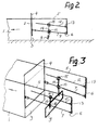
- Fig. 1 shows a box-like device 1, see also Fig. 3 , where in a rear end wall 2 there is an opening 3 the exit area of which can be adjusted by means of a plate 4 that is capable of being raised and lowered.
- the end wall 2 is the rear wall of the box 1 because during smoothing or levelling the box is moved in the direction of the arrow (to the left on the drawings).
- the plate 4 can be raised and lowered by using non-illustrated means, for example, one or more hydraulic working cylinders. This will be shown and discussed in more detail below in connection with Figs. 4-7 .
- One (or for example two) supporting arms 5 project backwards from the box 1.
- the supporting arm 5 is angular and forms an articulated support 6 for a rod 7 the other end of which is articulately supported on the plate 4 at 8.
- the articulated support 8 there is indicated a certain scope for telescopic movement to compensate for changes in length when the plate 4 is moved up and down, thereby swinging the rod 7 in the vertical plane about the articulated support 6 on the arm 5.
- the joints 6 and 8 could be made so slack that this in itself would provide the necessary length compensation.
- the rod 7 supports a blade 9.
- the blade 9 is supported by the rod 7 via a sleeve 10 that can be moved on the rod 7 in the longitudinal direction of the rod and fixed at a desired point on the rod, continuously or optionally in steps (locking pin holes).
- the blade 9, i.e., the supporting sleeve 10, is placed close to the joint 8 and thus close to the blade 4.
- the plate 4 is shown in a lowered position, i.e., in a position in which it blocks the opening 2.
- the blade 9 is at the same level as the lower edge of the plate 4.
- the blade 9 will also be raised, but depending on the distance between the sleeve 10 and the joint 8, the length b that the blade is lifted will differ from the lifting length a of the plate. This is due to the leverage that is provided between the plate and the blade.
- the blade 9 By moving the blade 9 along the rod 7, it is possible to set a reduction ratio between the plate 4 and the blade 9. This means that in, for example, the setting shown at the bottom of Fig. 1 , smoothing material will flow out through the discharge opening 3 when the box 1 is moved forwards in the direction of the arrow, and this material will be spread out in a larger width by the blade 9, as determined by the setting between the movement of the plate and the movement of the blade.
- the blade 9 is made having a width corresponding to the width that is to be laid, and which thus is larger than the width defined by the box 1.
- a parallel rod 12 is arranged parallel to the rod 7 and is articulately supported in the supporting arm 5 at 13.
- the blade 9 is attached to a rod 14 that is pivotally connected to a respective sleeve 10, 15 which can be moved along the rod 7 and the parallel rod 12 respectively and fixed there in the same way as discussed earlier.
- Fig. 3 is a purely schematic illustration of an advantageous embodiment in which two parallel supporting arms 5 are used.
- a construction of this kind is particularly advantageous because the whole apparatus can thereby be made symmetrical about the longitudinal axis of the box.
- the transverse dimension of the box i.e., by changing the non-illustrated front wall of the box and the rear end wall of the box with the plate 4, the width of the box can be changed, keeping the supporting arms 5 and the equipment suspended thereby.
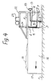
- the apparatus according to the invention can, for example, be made as shown in Figs. 4-6 .
- the apparatus shown in Figs. 4-6 is a leveller comprising a box-like device which has two side walls 16 (only one side wall is shown in Fig. 4 ), a front end wall 17 and a back end wall 2 (the same reference numerals are used here as in the schematic Figs. 1-3 ).
- a smoothing material 18 is placed in the box-like device 1.
- the box-like device 1 may optionally be bottomless, or have a partial bottom or a complete bottom (not shown).
- the longitudinal side walls 16 are optionally braced by non-illustrated transverse bars.
- the rear end wall 2 has an opening that extends upwards from the bottom edge and whose discharge opening 3, as previously mentioned, can be adjusted by means of a plate 4 that is capable of being raised and lowered.
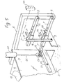
- a levelling material 18 is indicated in the box 1, but for clarity, the material has been omitted in the bottom part of Fig. 5 , i.e., the area close to the discharge opening 3 and the blade 9.
- Two parallel supporting arms 5 are welded in place at the top of the box 1, i.e., that the illustrated practical embodiment is made in the same way as the basic embodiment shown in Fig. 3 .
- a rod 7 is supported in each supporting arm 5.
- each rod 7 is telescopic, and in the exemplary embodiment the rod consists of a rectangular tube that is supported in the supporting arm 5 at 6 and accommodates a rectangular rod 7'.
- the rod 7, 7' is articulately connected at 19 to a lever arm 20 which in the middle is tiltably supported in the plate 4 by means of a swing bolt 21.
- Two working cylinders 24 are shown in the exemplary embodiment.
- a working cylinder 24 is found at one end of the lever arm and is connected to the lever arm by means of a yoke 25 formed on the end of the working cylinder piston rod 26.
- a similar working cylinder with piston rod is arranged at the other end of the lever arm 20, next to the other supporting arm 5.
- the blade 9 is suspended from two rods 14 (only one is shown).
- the rod 14 is articulately connected at 28 and 27 to respectively a sleeve 10 and a sleeve 15 which are slidably arranged on the rod 7 and the parallel rod 12 respectively.
- In the rod 7 and the parallel rod 12 there are locking pin holes 29, designed for cooperation with a respective locking pin 30, 31 in the sleeve 10 and 15 respectively. In this way, the sleeve 10 and 15 can be moved on the respective rod 7, 12 and fixed step by step in accordance with the holes 29.
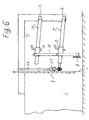
- Fig. 7 shows a modified embodiment, where the working cylinders 24, 26 are connected directly to the plate 4 and where the two parallel rods 7 are articulately connected directly to the plate 6 as indicated by 8.
- the box 1 For smoothing or levelling, the box 1 is moved in the direction of the arrow.
- the smoothing material 18 will flow out through the discharge opening 3 and will be spread by the following blade 9 in a width larger than the width of the discharge opening 3 and which is determined by the leverage between plate 4 and blade 9.
- the blade 9 can be connected to a levelling system, in Figs. 4 and 5 indicated as a laser reflector 33.
- Laser beams are sent from an installed laser transmitter to the reflector 33, and deviation from the desired levelling will be detected and signalled to a suitable device which will cause the working cylinder or the working cylinders 24, 26 to be actuated in a desired direction and distance.
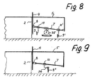
- Fig. 8 shows a variant with two blades 9, 9' arranged one after the other and at a different height above the ground.
- a compactor 35 is suspended from the bar 7 between the two blades 9, 9'.
- Fig. 9 shows a variant where the blade 9" is slidingly suspended on a bent bar 36.
- the blade can be tilted in the horizontal plane.
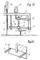
- Figs. 10 and 11 show an embodiment in which a box 1' is towed by a small crawler 37 which includes a loading box 9 tiltable by working cylinder 38.
- the loading box 39 contains material, which can be transferred to the box 1' by tilting ( Fig. 11 ) the loading box.
- the new apparatus permits a rapid and accurate smoothing/levelling.
- the apparatus can be towed or can be self-propelled, for example with crawler belts.
- the apparatus can optionally be provided with a device (not shown) for laying sheeting or the like, before or after the levelling operation.
- the plate is raised and lowered by suitable means, preferably one or two hydraulic working cylinders.
- suitable means preferably one or two hydraulic working cylinders.
- the working cylinder/cylinders could instead act on the levers/rods 7 or on the parallel rods 13, and thus act indirectly on the plate.
- Fig. 12 is a purely schematic illustration of another preferred embodiment where a blade 9 is suspended in a parallelogram arrangement comprising a supporting arm 5 where a parallel rod 12 is articulately supported at 13.
- the parallel rod 12 runs parallel with the rod 7, which is supported at 6.
- the blade 9 is attached to a rod 14 that is pivotally 40, 41 connected to a respective sleeve 10, 15 that can be moved along the rod 7 and the parallel rod 12 respectively and can be fixed there in the same way as discussed earlier.
- There is a parallelogram arrangement of this kind on each blade side see, e.g., Fig. 3 ).
- a working cylinder 42 is connected to the parallel rods 12 for raising and lowering the blade 9.
- the two rods 7 are extended in the direction of the plate 4, which can be raised and lowered by a working cylinder 43.
- a control device 44 for activation of the movement of the working cylinders 43.
- the control device is actuated by a light beam 45 which passes between the two ends of the rods 7 facing the plate 4.
- the light beam 45 forms an indirect connection between the rods 7 and actuates the control device 44. If the light beam moves up, the control device 44 is actuated and causes the working cylinder 43 and the plate 4 to move up, and conversely, if the light beams 45 moves down, the plate 4 moves down in the set situation.
- Fig. 13 is a purely schematic illustration of how the rods 7, instead of having an indirect connection (the light beam 45), can be connected directly to an elastic band 46 which actuates a switch 47 in the box (the control device) 44.
- Figs. 12 and 13 can also be made as pure lever embodiments (as for example in Fig. 1 ).
Landscapes
- Engineering & Computer Science (AREA)
- Architecture (AREA)
- Civil Engineering (AREA)
- Structural Engineering (AREA)
- Road Paving Machines (AREA)
- Mechanical Treatment Of Semiconductor (AREA)
- Soil Working Implements (AREA)
- Finish Polishing, Edge Sharpening, And Grinding By Specific Grinding Devices (AREA)
- Road Repair (AREA)
- Underground Or Underwater Handling Of Building Materials (AREA)
- Machine Tool Units (AREA)
Applications Claiming Priority (3)
| Application Number | Priority Date | Filing Date | Title |
|---|---|---|---|
| NO20011147 | 2001-10-01 | ||
| NO20014763A NO316028B1 (no) | 2001-10-01 | 2001-10-01 | Fremgangsmåte ved og anordning for planering av et underlag |
| PCT/NO2002/000350 WO2003029561A1 (en) | 2001-10-01 | 2002-10-01 | Method and device for levelling of a surface |
Publications (2)
| Publication Number | Publication Date |
|---|---|
| EP1440207A1 EP1440207A1 (en) | 2004-07-28 |
| EP1440207B1 true EP1440207B1 (en) | 2009-02-25 |
Family
ID=19912882
Family Applications (1)
| Application Number | Title | Priority Date | Filing Date |
|---|---|---|---|
| EP02768181A Expired - Lifetime EP1440207B1 (en) | 2001-10-01 | 2002-10-01 | Method and device for levelling of a surface |
Country Status (13)
Families Citing this family (5)
| Publication number | Priority date | Publication date | Assignee | Title |
|---|---|---|---|---|
| CN102431812B (zh) * | 2011-09-22 | 2013-06-19 | 新疆天物科技发展有限公司 | 多功能平整料堆机 |
| US8979425B2 (en) | 2012-10-30 | 2015-03-17 | Caterpillar Paving Products Inc. | Screed extender speed control |
| US9797098B2 (en) * | 2015-08-19 | 2017-10-24 | George Guilmette | Aggregate spreading system |
| DE102016225502B4 (de) * | 2016-12-19 | 2019-01-03 | Moba Mobile Automation Ag | Messsystem zur Schichtdickenerfassung |
| US11293149B2 (en) * | 2019-03-08 | 2022-04-05 | Caterpillar Paving Products Inc. | Stiffened screed extender tube |
Family Cites Families (17)
| Publication number | Priority date | Publication date | Assignee | Title |
|---|---|---|---|---|
| US2092458A (en) * | 1934-11-15 | 1937-09-07 | Krout Dale | Combination road machine |
| US3403609A (en) * | 1966-03-01 | 1968-10-01 | California Fresno Asphalt Co | Material spreading device |
| US3891338A (en) * | 1973-04-30 | 1975-06-24 | Barber Greene Co | Convergent link system for connecting a screed to the traction unit of a paving machine |
| US3907451A (en) * | 1974-01-28 | 1975-09-23 | Lay Mor Manufacturing Company | Extensible screed and auger assembly for a road paving machine |
| US3901616A (en) * | 1974-07-22 | 1975-08-26 | Kenneth J Greening | Self-propelled paver |
| US3909146A (en) * | 1974-09-23 | 1975-09-30 | Allatt Ltd | Paving machine |
| US4379653A (en) * | 1981-06-01 | 1983-04-12 | White Consolidated Industries, Inc. | Asphalt paver with telescoping screed |
| US4842441A (en) * | 1987-02-10 | 1989-06-27 | Mable M. Watkins | Apparatus for filling a trench in a paved surface |
| US4765772A (en) * | 1987-05-29 | 1988-08-23 | Angelo Benedetti, Inc. | Method and apparatus for filling voids in recycled asphalt |
| US4863310A (en) * | 1988-10-11 | 1989-09-05 | Jeffrey Reed | Paving apparatus |
| GB2226839B (en) * | 1989-01-06 | 1993-01-13 | George Byerley | Road-laying machine |
| US5232305A (en) * | 1991-05-15 | 1993-08-03 | Caterpillar Paving Products Inc. | Paving material distribution system |
| US5868522A (en) * | 1997-01-16 | 1999-02-09 | Astec Industries, Inc. | Vibratory screed assembly for an asphalt paving machine |
| US6171018B1 (en) * | 1997-11-10 | 2001-01-09 | Kabushiki Kaisha Topcon | Automatic control system for construction machinery |
| US6050744A (en) | 1998-02-09 | 2000-04-18 | Binning; Burleigh | Path paver machine |
| US6398453B1 (en) * | 1998-07-30 | 2002-06-04 | Akzo Nobel Asphalt Applications, Inc. | Telescoping spreader box with replaceable strike-off system |
| NO309239B1 (no) * | 1999-04-13 | 2001-01-02 | Jan Skughei | Materialutlegger, særlig for utlegging av asfalt på små arealer |
-
2001
- 2001-10-01 NO NO20014763A patent/NO316028B1/no not_active IP Right Cessation
-
2002
- 2002-10-01 JP JP2003532762A patent/JP2005504200A/ja active Pending
- 2002-10-01 BR BR0212980-9A patent/BR0212980A/pt not_active IP Right Cessation
- 2002-10-01 DK DK02768181T patent/DK1440207T3/da active
- 2002-10-01 AU AU2002330782A patent/AU2002330782B2/en not_active Ceased
- 2002-10-01 EP EP02768181A patent/EP1440207B1/en not_active Expired - Lifetime
- 2002-10-01 AT AT02768181T patent/ATE423871T1/de not_active IP Right Cessation
- 2002-10-01 US US10/490,800 patent/US7182549B2/en not_active Expired - Fee Related
- 2002-10-01 DE DE60231317T patent/DE60231317D1/de not_active Expired - Lifetime
- 2002-10-01 CN CNA028194659A patent/CN1561423A/zh active Pending
- 2002-10-01 WO PCT/NO2002/000350 patent/WO2003029561A1/en active IP Right Grant
- 2002-10-01 CA CA002461660A patent/CA2461660C/en not_active Expired - Fee Related
- 2002-10-01 ES ES02768181T patent/ES2323166T3/es not_active Expired - Lifetime
Also Published As
| Publication number | Publication date |
|---|---|
| ES2323166T3 (es) | 2009-07-08 |
| NO20014763L (no) | 2003-04-02 |
| CN1561423A (zh) | 2005-01-05 |
| US20060275079A1 (en) | 2006-12-07 |
| WO2003029561A1 (en) | 2003-04-10 |
| BR0212980A (pt) | 2004-10-13 |
| AU2002330782B2 (en) | 2007-03-22 |
| DE60231317D1 (de) | 2009-04-09 |
| NO20014763D0 (no) | 2001-10-01 |
| CA2461660C (en) | 2010-03-09 |
| CA2461660A1 (en) | 2003-04-10 |
| EP1440207A1 (en) | 2004-07-28 |
| WO2003029561A8 (en) | 2004-05-06 |
| US7182549B2 (en) | 2007-02-27 |
| AU2002330782A2 (en) | 2003-04-14 |
| ATE423871T1 (de) | 2009-03-15 |
| NO316028B1 (no) | 2003-12-01 |
| DK1440207T3 (da) | 2009-06-22 |
| JP2005504200A (ja) | 2005-02-10 |
Similar Documents
| Publication | Publication Date | Title |
|---|---|---|
| US3970405A (en) | Slipform paving apparatus | |
| US8128314B2 (en) | Paving screed and a method for laying a paving mat | |
| US7559719B2 (en) | Screed attachment for skid steer vehicle | |
| US6322287B1 (en) | Aggregate grading machine | |
| US5599135A (en) | Asphalt spreader | |
| US3019536A (en) | Railway ballast equipment | |
| US3776318A (en) | Earth working machine including scraper blade means | |
| JPS596964B2 (ja) | 護岸舗装用装具 | |
| US3877830A (en) | Towed paver with thickness and leveling control | |
| US3856425A (en) | Adjustable side for slip form | |
| GB1590269A (en) | Ballast regulator side plow | |
| EP1440207B1 (en) | Method and device for levelling of a surface | |
| US5173005A (en) | Prime mover actuated concrete curb extruder | |
| US7500804B2 (en) | Compaction wheel system and method | |
| AU2002330782A1 (en) | Method and device for levelling of a surface | |
| US4869326A (en) | Box scraper with plural blades | |
| EP0774542B1 (en) | Road paver-finisher with automatic control of the height of the transverse augers with respect to the screed | |
| US3566759A (en) | Mounting arrangement for sidewalk building equipment or the like | |
| JP2005504200A6 (ja) | 地表面を平らにする方法及び装置 | |
| US3466989A (en) | Earth materials handling apparatus | |
| US3891338A (en) | Convergent link system for connecting a screed to the traction unit of a paving machine | |
| US3905715A (en) | Track driven machines with torsion bar-activated controls | |
| US8256986B2 (en) | Machine for paving concrete paths | |
| US3228311A (en) | Spreader | |
| SU850777A1 (ru) | Навесное оборудование дл РАСпРЕдЕлЕНи , уплОТНЕНи изАглАжиВАНи бЕТОННыХ СМЕСЕй |
Legal Events
| Date | Code | Title | Description |
|---|---|---|---|
| PUAI | Public reference made under article 153(3) epc to a published international application that has entered the european phase |
Free format text: ORIGINAL CODE: 0009012 |
|
| 17P | Request for examination filed |
Effective date: 20040406 |
|
| AK | Designated contracting states |
Kind code of ref document: A1 Designated state(s): AT BE BG CH CY CZ DE DK EE ES FI FR GB GR IE IT LI LU MC NL PT SE SK TR |
|
| AX | Request for extension of the european patent |
Extension state: AL LT LV MK RO SI |
|
| GRAP | Despatch of communication of intention to grant a patent |
Free format text: ORIGINAL CODE: EPIDOSNIGR1 |
|
| GRAS | Grant fee paid |
Free format text: ORIGINAL CODE: EPIDOSNIGR3 |
|
| GRAA | (expected) grant |
Free format text: ORIGINAL CODE: 0009210 |
|
| AK | Designated contracting states |
Kind code of ref document: B1 Designated state(s): AT BE BG CH CY CZ DE DK EE ES FI FR GB GR IE IT LI LU MC NL PT SE SK TR |
|
| REG | Reference to a national code |
Ref country code: GB Ref legal event code: FG4D |
|
| REG | Reference to a national code |
Ref country code: CH Ref legal event code: EP |
|
| REG | Reference to a national code |
Ref country code: IE Ref legal event code: FG4D |
|
| REF | Corresponds to: |
Ref document number: 60231317 Country of ref document: DE Date of ref document: 20090409 Kind code of ref document: P |
|
| REG | Reference to a national code |
Ref country code: SE Ref legal event code: TRGR |
|
| REG | Reference to a national code |
Ref country code: DK Ref legal event code: T3 |
|
| REG | Reference to a national code |
Ref country code: ES Ref legal event code: FG2A Ref document number: 2323166 Country of ref document: ES Kind code of ref document: T3 |
|
| PG25 | Lapsed in a contracting state [announced via postgrant information from national office to epo] |
Ref country code: NL Free format text: LAPSE BECAUSE OF FAILURE TO SUBMIT A TRANSLATION OF THE DESCRIPTION OR TO PAY THE FEE WITHIN THE PRESCRIBED TIME-LIMIT Effective date: 20090225 |
|
| NLV1 | Nl: lapsed or annulled due to failure to fulfill the requirements of art. 29p and 29m of the patents act | ||
| PG25 | Lapsed in a contracting state [announced via postgrant information from national office to epo] |
Ref country code: AT Free format text: LAPSE BECAUSE OF FAILURE TO SUBMIT A TRANSLATION OF THE DESCRIPTION OR TO PAY THE FEE WITHIN THE PRESCRIBED TIME-LIMIT Effective date: 20090225 |
|
| PG25 | Lapsed in a contracting state [announced via postgrant information from national office to epo] |
Ref country code: BE Free format text: LAPSE BECAUSE OF FAILURE TO SUBMIT A TRANSLATION OF THE DESCRIPTION OR TO PAY THE FEE WITHIN THE PRESCRIBED TIME-LIMIT Effective date: 20090225 |
|
| PG25 | Lapsed in a contracting state [announced via postgrant information from national office to epo] |
Ref country code: PT Free format text: LAPSE BECAUSE OF FAILURE TO SUBMIT A TRANSLATION OF THE DESCRIPTION OR TO PAY THE FEE WITHIN THE PRESCRIBED TIME-LIMIT Effective date: 20090812 Ref country code: CZ Free format text: LAPSE BECAUSE OF FAILURE TO SUBMIT A TRANSLATION OF THE DESCRIPTION OR TO PAY THE FEE WITHIN THE PRESCRIBED TIME-LIMIT Effective date: 20090225 Ref country code: EE Free format text: LAPSE BECAUSE OF FAILURE TO SUBMIT A TRANSLATION OF THE DESCRIPTION OR TO PAY THE FEE WITHIN THE PRESCRIBED TIME-LIMIT Effective date: 20090225 |
|
| PG25 | Lapsed in a contracting state [announced via postgrant information from national office to epo] |
Ref country code: SK Free format text: LAPSE BECAUSE OF FAILURE TO SUBMIT A TRANSLATION OF THE DESCRIPTION OR TO PAY THE FEE WITHIN THE PRESCRIBED TIME-LIMIT Effective date: 20090225 |
|
| PLBE | No opposition filed within time limit |
Free format text: ORIGINAL CODE: 0009261 |
|
| STAA | Information on the status of an ep patent application or granted ep patent |
Free format text: STATUS: NO OPPOSITION FILED WITHIN TIME LIMIT |
|
| PG25 | Lapsed in a contracting state [announced via postgrant information from national office to epo] |
Ref country code: BG Free format text: LAPSE BECAUSE OF FAILURE TO SUBMIT A TRANSLATION OF THE DESCRIPTION OR TO PAY THE FEE WITHIN THE PRESCRIBED TIME-LIMIT Effective date: 20090525 |
|
| 26N | No opposition filed |
Effective date: 20091126 |
|
| PG25 | Lapsed in a contracting state [announced via postgrant information from national office to epo] |
Ref country code: MC Free format text: LAPSE BECAUSE OF NON-PAYMENT OF DUE FEES Effective date: 20091031 |
|
| REG | Reference to a national code |
Ref country code: CH Ref legal event code: PL |
|
| REG | Reference to a national code |
Ref country code: IE Ref legal event code: MM4A |
|
| PG25 | Lapsed in a contracting state [announced via postgrant information from national office to epo] |
Ref country code: IE Free format text: LAPSE BECAUSE OF NON-PAYMENT OF DUE FEES Effective date: 20091001 Ref country code: LI Free format text: LAPSE BECAUSE OF NON-PAYMENT OF DUE FEES Effective date: 20091031 Ref country code: CH Free format text: LAPSE BECAUSE OF NON-PAYMENT OF DUE FEES Effective date: 20091031 Ref country code: GR Free format text: LAPSE BECAUSE OF FAILURE TO SUBMIT A TRANSLATION OF THE DESCRIPTION OR TO PAY THE FEE WITHIN THE PRESCRIBED TIME-LIMIT Effective date: 20090526 |
|
| PG25 | Lapsed in a contracting state [announced via postgrant information from national office to epo] |
Ref country code: IT Free format text: LAPSE BECAUSE OF NON-PAYMENT OF DUE FEES Effective date: 20091001 |
|
| PG25 | Lapsed in a contracting state [announced via postgrant information from national office to epo] |
Ref country code: LU Free format text: LAPSE BECAUSE OF NON-PAYMENT OF DUE FEES Effective date: 20091001 |
|
| PGRI | Patent reinstated in contracting state [announced from national office to epo] |
Ref country code: IT Effective date: 20110616 |
|
| PG25 | Lapsed in a contracting state [announced via postgrant information from national office to epo] |
Ref country code: TR Free format text: LAPSE BECAUSE OF FAILURE TO SUBMIT A TRANSLATION OF THE DESCRIPTION OR TO PAY THE FEE WITHIN THE PRESCRIBED TIME-LIMIT Effective date: 20090225 |
|
| PG25 | Lapsed in a contracting state [announced via postgrant information from national office to epo] |
Ref country code: CY Free format text: LAPSE BECAUSE OF FAILURE TO SUBMIT A TRANSLATION OF THE DESCRIPTION OR TO PAY THE FEE WITHIN THE PRESCRIBED TIME-LIMIT Effective date: 20090225 |
|
| PGFP | Annual fee paid to national office [announced via postgrant information from national office to epo] |
Ref country code: GB Payment date: 20130925 Year of fee payment: 12 |
|
| PGFP | Annual fee paid to national office [announced via postgrant information from national office to epo] |
Ref country code: DK Payment date: 20131010 Year of fee payment: 12 |
|
| PGFP | Annual fee paid to national office [announced via postgrant information from national office to epo] |
Ref country code: FR Payment date: 20131009 Year of fee payment: 12 Ref country code: SE Payment date: 20131011 Year of fee payment: 12 |
|
| PGFP | Annual fee paid to national office [announced via postgrant information from national office to epo] |
Ref country code: FI Payment date: 20131010 Year of fee payment: 12 |
|
| PGFP | Annual fee paid to national office [announced via postgrant information from national office to epo] |
Ref country code: ES Payment date: 20140911 Year of fee payment: 13 |
|
| PGFP | Annual fee paid to national office [announced via postgrant information from national office to epo] |
Ref country code: DE Payment date: 20140923 Year of fee payment: 13 |
|
| PGFP | Annual fee paid to national office [announced via postgrant information from national office to epo] |
Ref country code: IT Payment date: 20140908 Year of fee payment: 13 |
|
| REG | Reference to a national code |
Ref country code: DK Ref legal event code: EBP Effective date: 20141031 |
|
| REG | Reference to a national code |
Ref country code: SE Ref legal event code: EUG |
|
| GBPC | Gb: european patent ceased through non-payment of renewal fee |
Effective date: 20141001 |
|
| PG25 | Lapsed in a contracting state [announced via postgrant information from national office to epo] |
Ref country code: SE Free format text: LAPSE BECAUSE OF NON-PAYMENT OF DUE FEES Effective date: 20141002 Ref country code: FI Free format text: LAPSE BECAUSE OF NON-PAYMENT OF DUE FEES Effective date: 20141001 Ref country code: GB Free format text: LAPSE BECAUSE OF NON-PAYMENT OF DUE FEES Effective date: 20141001 |
|
| REG | Reference to a national code |
Ref country code: FR Ref legal event code: ST Effective date: 20150630 |
|
| PG25 | Lapsed in a contracting state [announced via postgrant information from national office to epo] |
Ref country code: FR Free format text: LAPSE BECAUSE OF NON-PAYMENT OF DUE FEES Effective date: 20141031 |
|
| PG25 | Lapsed in a contracting state [announced via postgrant information from national office to epo] |
Ref country code: DK Free format text: LAPSE BECAUSE OF NON-PAYMENT OF DUE FEES Effective date: 20141031 |
|
| REG | Reference to a national code |
Ref country code: DE Ref legal event code: R119 Ref document number: 60231317 Country of ref document: DE |
|
| PG25 | Lapsed in a contracting state [announced via postgrant information from national office to epo] |
Ref country code: IT Free format text: LAPSE BECAUSE OF NON-PAYMENT OF DUE FEES Effective date: 20151001 Ref country code: DE Free format text: LAPSE BECAUSE OF NON-PAYMENT OF DUE FEES Effective date: 20160503 |
|
| REG | Reference to a national code |
Ref country code: ES Ref legal event code: FD2A Effective date: 20170206 |
|
| PG25 | Lapsed in a contracting state [announced via postgrant information from national office to epo] |
Ref country code: ES Free format text: LAPSE BECAUSE OF NON-PAYMENT OF DUE FEES Effective date: 20151002 |