EP1439408A2 - Breitbandig dispersionskontrollierte optische Faser - Google Patents
Breitbandig dispersionskontrollierte optische Faser Download PDFInfo
- Publication number
- EP1439408A2 EP1439408A2 EP03018711A EP03018711A EP1439408A2 EP 1439408 A2 EP1439408 A2 EP 1439408A2 EP 03018711 A EP03018711 A EP 03018711A EP 03018711 A EP03018711 A EP 03018711A EP 1439408 A2 EP1439408 A2 EP 1439408A2
- Authority
- EP
- European Patent Office
- Prior art keywords
- optical fiber
- wavelength
- dispersion
- band
- less
- Prior art date
- Legal status (The legal status is an assumption and is not a legal conclusion. Google has not performed a legal analysis and makes no representation as to the accuracy of the status listed.)
- Ceased
Links
Images




Classifications
-
- G—PHYSICS
- G02—OPTICS
- G02B—OPTICAL ELEMENTS, SYSTEMS OR APPARATUS
- G02B6/00—Light guides; Structural details of arrangements comprising light guides and other optical elements, e.g. couplings
- G02B6/02—Optical fibres with cladding with or without a coating
-
- G—PHYSICS
- G02—OPTICS
- G02B—OPTICAL ELEMENTS, SYSTEMS OR APPARATUS
- G02B6/00—Light guides; Structural details of arrangements comprising light guides and other optical elements, e.g. couplings
- G02B6/02—Optical fibres with cladding with or without a coating
- G02B6/036—Optical fibres with cladding with or without a coating core or cladding comprising multiple layers
- G02B6/03616—Optical fibres characterised both by the number of different refractive index layers around the central core segment, i.e. around the innermost high index core layer, and their relative refractive index difference
- G02B6/03622—Optical fibres characterised both by the number of different refractive index layers around the central core segment, i.e. around the innermost high index core layer, and their relative refractive index difference having 2 layers only
- G02B6/03633—Optical fibres characterised both by the number of different refractive index layers around the central core segment, i.e. around the innermost high index core layer, and their relative refractive index difference having 2 layers only arranged - -
-
- G—PHYSICS
- G02—OPTICS
- G02B—OPTICAL ELEMENTS, SYSTEMS OR APPARATUS
- G02B6/00—Light guides; Structural details of arrangements comprising light guides and other optical elements, e.g. couplings
- G02B6/02—Optical fibres with cladding with or without a coating
- G02B6/02004—Optical fibres with cladding with or without a coating characterised by the core effective area or mode field radius
- G02B6/02009—Large effective area or mode field radius, e.g. to reduce nonlinear effects in single mode fibres
- G02B6/02014—Effective area greater than 60 square microns in the C band, i.e. 1530-1565 nm
-
- G—PHYSICS
- G02—OPTICS
- G02B—OPTICAL ELEMENTS, SYSTEMS OR APPARATUS
- G02B6/00—Light guides; Structural details of arrangements comprising light guides and other optical elements, e.g. couplings
- G02B6/02—Optical fibres with cladding with or without a coating
- G02B6/02214—Optical fibres with cladding with or without a coating tailored to obtain the desired dispersion, e.g. dispersion shifted, dispersion flattened
- G02B6/02219—Characterised by the wavelength dispersion properties in the silica low loss window around 1550 nm, i.e. S, C, L and U bands from 1460-1675 nm
- G02B6/02223—Dual window fibres, i.e. characterised by dispersion properties around 1550 nm and in at least another wavelength window, e.g. 1310 nm
-
- G—PHYSICS
- G02—OPTICS
- G02B—OPTICAL ELEMENTS, SYSTEMS OR APPARATUS
- G02B6/00—Light guides; Structural details of arrangements comprising light guides and other optical elements, e.g. couplings
- G02B6/02—Optical fibres with cladding with or without a coating
- G02B6/02214—Optical fibres with cladding with or without a coating tailored to obtain the desired dispersion, e.g. dispersion shifted, dispersion flattened
- G02B6/02219—Characterised by the wavelength dispersion properties in the silica low loss window around 1550 nm, i.e. S, C, L and U bands from 1460-1675 nm
- G02B6/02228—Dispersion flattened fibres, i.e. having a low dispersion variation over an extended wavelength range
- G02B6/02238—Low dispersion slope fibres
-
- G—PHYSICS
- G02—OPTICS
- G02B—OPTICAL ELEMENTS, SYSTEMS OR APPARATUS
- G02B6/00—Light guides; Structural details of arrangements comprising light guides and other optical elements, e.g. couplings
- G02B6/02—Optical fibres with cladding with or without a coating
- G02B6/028—Optical fibres with cladding with or without a coating with core or cladding having graded refractive index
- G02B6/0281—Graded index region forming part of the central core segment, e.g. alpha profile, triangular, trapezoidal core
-
- H—ELECTRICITY
- H01—ELECTRIC ELEMENTS
- H01S—DEVICES USING THE PROCESS OF LIGHT AMPLIFICATION BY STIMULATED EMISSION OF RADIATION [LASER] TO AMPLIFY OR GENERATE LIGHT; DEVICES USING STIMULATED EMISSION OF ELECTROMAGNETIC RADIATION IN WAVE RANGES OTHER THAN OPTICAL
- H01S3/00—Lasers, i.e. devices using stimulated emission of electromagnetic radiation in the infrared, visible or ultraviolet wave range
- H01S3/05—Construction or shape of optical resonators; Accommodation of active medium therein; Shape of active medium
- H01S3/06—Construction or shape of active medium
- H01S3/063—Waveguide lasers, i.e. whereby the dimensions of the waveguide are of the order of the light wavelength
- H01S3/067—Fibre lasers
- H01S3/06708—Constructional details of the fibre, e.g. compositions, cross-section, shape or tapering
- H01S3/06725—Fibre characterized by a specific dispersion, e.g. for pulse shaping in soliton lasers or for dispersion compensating [DCF]
-
- H—ELECTRICITY
- H01—ELECTRIC ELEMENTS
- H01S—DEVICES USING THE PROCESS OF LIGHT AMPLIFICATION BY STIMULATED EMISSION OF RADIATION [LASER] TO AMPLIFY OR GENERATE LIGHT; DEVICES USING STIMULATED EMISSION OF ELECTROMAGNETIC RADIATION IN WAVE RANGES OTHER THAN OPTICAL
- H01S3/00—Lasers, i.e. devices using stimulated emission of electromagnetic radiation in the infrared, visible or ultraviolet wave range
- H01S3/05—Construction or shape of optical resonators; Accommodation of active medium therein; Shape of active medium
- H01S3/06—Construction or shape of active medium
- H01S3/063—Waveguide lasers, i.e. whereby the dimensions of the waveguide are of the order of the light wavelength
- H01S3/067—Fibre lasers
- H01S3/06708—Constructional details of the fibre, e.g. compositions, cross-section, shape or tapering
- H01S3/06729—Peculiar transverse fibre profile
-
- H—ELECTRICITY
- H01—ELECTRIC ELEMENTS
- H01S—DEVICES USING THE PROCESS OF LIGHT AMPLIFICATION BY STIMULATED EMISSION OF RADIATION [LASER] TO AMPLIFY OR GENERATE LIGHT; DEVICES USING STIMULATED EMISSION OF ELECTROMAGNETIC RADIATION IN WAVE RANGES OTHER THAN OPTICAL
- H01S3/00—Lasers, i.e. devices using stimulated emission of electromagnetic radiation in the infrared, visible or ultraviolet wave range
- H01S3/30—Lasers, i.e. devices using stimulated emission of electromagnetic radiation in the infrared, visible or ultraviolet wave range using scattering effects, e.g. stimulated Brillouin or Raman effects
- H01S3/302—Lasers, i.e. devices using stimulated emission of electromagnetic radiation in the infrared, visible or ultraviolet wave range using scattering effects, e.g. stimulated Brillouin or Raman effects in an optical fibre
Definitions
- the present invention relates to an optical fiber, and in particular to a wide-band dispersion controlled optical fiber which is capable of being used for medium/long distance transmission while using optical signals of wide wavelength band.
- N optical signals with different wavelengths are multiplexed and concurrently transmitted through one strand of an optical fiber.
- the C-band wavelength region (1530 nm to 1565 nm) and the L-band wavelength region (1570 nm to 1605 nm) are principally used in the optical signals transmitted through the optical fiber, in which the transmission characteristic of optical signals is good.
- researches have been vigorously made in order to use the O-band wavelength region (1285 nm to 1330 nm) and the S-band wavelength region (1460 nm to 1530 nm).
- FIG. 1 is a graph showing the dispersion properties of optical fibers according to an example of the prior art.
- a first curve 11 shows a dispersion characteristic of a single mode optical fiber.
- Second and third curves 13 and 15 show dispersion properties of positive dispersion optical fibers, respectively.
- a fourth curve 17 shows a dispersion characteristic of a negative dispersion optical fiber.
- Second and third curves 13 and 15 indicate optical fibers which have positive dispersion values at 1550 nm wavelength
- fourth curve 17 indicates an optical fiber which has a negative dispersion value at 1550 nm wavelength.
- the C-band wavelength region exhibits dispersion values in the range of 14 to 19 ps/nm/km and the L-band wavelength region exhibits dispersion values larger than those in the C-band wavelength region. Therefore, a dispersion compensator is essentially required in order to employ such a single mode optical fiber in wide-band/large-capacity communication networks, if a single mode optical fiber exhibits the dispersion characteristic as indicated by first curve 11 in WDM communication mode.
- a zero dispersion wavelength is positioned in the O-band wavelength region, which causes deterioration of signal quality due to Four Wave Mixing (FMW) at the time of receiving and sending an optical signal of the O-band wavelength region.
- the FMW is an example of a non-linear phenomenon produced when sending an optical signal. Due to FMW, two optical signals with different wavelengths are combined, thereby producing one or more new optical signals which distort the assigned optical signals.
- the FMW is generated at a zero dispersion wavelength at which the phases of optical signals coincide with each other.
- the single mode optical fiber with the dispersion characteristic as indicated by first curve 11 has large dispersion values. As a result, the cost is increased for compensating dispersion in WDM mode. Therefore, it is not efficient to construct a wide-band communication network using a single mode optical fiber in a WDM communication network. Accordingly, a single mode optical fiber is mainly used in Time Division Multiplexing (TDM) communication networks for wide-band/large-capacity transmission through the single mode optical fiber.
- TDM Time Division Multiplexing
- the WDM communication mode when compared to the TDM communication mode, is advantageous in that transmission capacity is greatly increased at small expense. Due to such an advantage, the WDM mode has been continuously developed for optical communication networks.
- Second curve 13 exhibits dispersion characteristic of a large effective area optical fiber which has an enlarged effective cross-section area.
- Third curve 15 indicates a reduced dispersion slope optical fiber which has a reduced dispersion slope.
- a large effective area optical fiber enlarges an effective cross-section area in order to achieve dispersion values which are not less than a predetermined level, thereby avoiding non-linear phenomena such as four wave mixing (FWM).
- FWM four wave mixing
- a large effective area optical fiber has relatively large dispersion values in the L-band wavelength region, dispersion compensation is essentially required.
- Raman amplification efficiency decreases.
- a reduced slope optical fiber with a dispersion characteristic as indicated by third curve 15 is reduced in difference of dispersion values between the C-band and L-band wavelength regions by reducing the dispersion slope. Therefore, the reduced slope optical fiber reduces the relative difference of dispersion values between the C-band and L-band in a wide-band/large-capacity communication network.
- the zero dispersion wavelength of a positive dispersion optical fiber is located in the wavelength region of 1460 nm to 1500 nm as indicated by the second and third curves, it is impossible to use Raman amplification which is used in long distance transmission. Due to the characteristic of the Raman amplification mode, a pumping light which has a wavelength about 100 nm lower than the optical signal that is amplified is used for optical fiber signal amplification. A pumping light of a wavelength region of 1470 nm to 1505 nm is used for amplifying an optical signal of the L-band wavelength region.
- the wavelengths of pumping light used for amplifying L-band optical signals in the Raman amplification mode are within the wavelength region in which the zero dispersion wavelength of a positive dispersion optical fiber is positioned. Because this induces a non-linear phenomenon such as FWM, it is not efficient to use a positive optical fiber as mentioned above in a wide-band/large-capacity communication network. In addition, a problem exists because the zero dispersion wavelength of a positive dispersion optical fiber is located in the S-band wavelength region of 1460 nm to 1530 nm. Thus, a non-linear phenomenon such as FWM is induced, and it is impossible to use the S-band wavelength region.
- a negative dispersion optical fiber with dispersion characteristic as indicated by fourth curve 17 has a zero dispersion wavelength positioned in the wavelength region of 1610 nm to 1700 nm. Therefore, it enables transmission of an optical signal of the C-band and L-band wavelength regions.
- Such a negative dispersion optical fiber is used only in middle/long distance transmission in the range of about several hundreds km. However, it cannot be used for an optical signal in the S-band or O-band wavelength region because absolute dispersion values are so large.
- optical communication networks in particular WDM communication networks have been continuously developed
- conventional optical fibers use only optical signals in the C-band wave length region or L-band wavelength region. This is because the positions of zero dispersion wavelengths or dispersion values are not capable of being tuned.
- a negative optical fiber is useful in middle/long distance transmission networks of about several hundreds km.
- a positive optical fiber is used in long distance transmission exceeding this range. Consequently, the construction cost of optical communication networks are dually increased, since different types of optical fibers are used in accordance with the transmission length.
- One object of the present invention is to provide a wide-band dispersion controlled optical fiber which is capable of transmitting optical signals of various wavelength regions and a wide-band dispersion controlled optical fiber which enables not only short distance transmission but also middle/long distance transmission using one type of optical fiber.
- a wide-band dispersion controlled optical fiber characterized in that the fiber is controlled/tuned, using respective core and clad diameters and distribution of refractive indexes, to have (1) the position of the zero dispersion wavelength, and (2) negative dispersion values in the O-band wavelength region and positive dispersion values with small deviations in the C-band and L-band wavelength regions.
- the a wide-band dispersion controlled optical fiber having includes a cut-off wavelength is 1285 nm or less, dispersion values are -12 to -4 ps/nm/km in a wavelength region of 1285 nm to 1330 nm and 8 to 14 ps/nm/km at 1625 nm wavelength, and a zero dispersion wavelength is positioned in a wavelength region below 1430 nm, wherein the effective cross-section area at 1550 nm wavelength is less than 75 ⁇ m 2 , and wherein the difference of losses between the 1550 nm wavelength and the 1625 nm wavelength is 0.03 dB/km or less.
- a wide-band dispersion controlled optical fiber having a cut-off wavelength is 1285 nm or less, dispersion values are - 12 ⁇ -4 ps/nm/km in a wavelength region of 1285 nm ⁇ 1330 nm and 8 ⁇ 14 ps/nm/km at 1625 nm wavelength, and dispersion slope is 0.074 ps/nm 2 /km or less at zero dispersion wavelength.
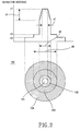
- FIG. 2 is a wide-band dispersion controlled optical fiber 100 according to a preferred embodiment of the present invention and a graph showing the distribution of refractive indexes of the optical fiber.
- wide-band dispersion controlled optical fiber 100 comprises an internal core 101, an external core 102, an internal clad 102, and an external clad 104.
- Internal core 101 has a constant refractive index n 1 and a diameter d1.
- External core 102 encloses internal core 101 and has a diameter d2, wherein the refractive index n2(r) decreases from n1 as advancing from the diameter d1 to the diameter d2.
- Internal clad 103 encloses external core 102 and has a diameter d3, wherein Internal clad 103 is evenly distributed with a refractive index n3 in the diametric direction, which is smaller than the refractive indexes n1 and n2(r).
- External clad 104 is constantly distributed with a refractive index n4 in the diametric direction, which is smaller that the refractive index n3 of internal clad 103.
- the diameter of internal core 101 is substantially zero and the refractive index may be acutely distributed at the center of external core 102.
- r is measured from the center of wide-band dispersion controlled optical fiber 101 and indicates a radius of an optional position within the external core, in which d1 ⁇ 2r ⁇ d2, d1 indicates the diameter of internal core 101, in which 0 ⁇ d1 ⁇ d2, and ⁇ co is a refractive index determining coefficient, in which 0 ⁇ ⁇ co ⁇
- Equation 2 0 ⁇ d 1 d 2 ⁇ 0.8 0.1 ⁇ d 2 d 3 ⁇ 0.5 Equation 3 0.0034 ⁇ n 1- n 4 n 1 ⁇ 0.007 0 ⁇ n 2- n 4 n 2 ⁇ 0.0048 0 ⁇ n 3- n 4 n 3 ⁇ 0.0014
- wide-band dispersion controlled optical fiber 100 with diameters and distribution of refractive indexes as described above is tuned so that a cut-off wavelength is controlled to 1285 nm or less, a dispersion value in the O-band wavelength region is in the range of -12 to -4 ps/nm/km, and a dispersion value of the 1625 nm wavelength is in the range of 8 to 14 ps/nm/km, and a zero dispersion wavelength is positioned in the wavelength region of less than 1430 nm.
- the dispersion slope at the zero dispersion wave is controlled to 0.0074 ps/nm 2 /km or less and the effective cross-section area is controlled to 75 ⁇ m 2 or less.
- dispersion controlled optical fiber 100 has negative dispersion values when transmitting an O-band optical signal in the wavelength region of 1285 to 1330 nm. Therefore, it is preferable that optical fiber 100 is applied to middle/short distance transmission of about several hundreds km.
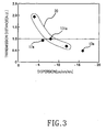
- FIG. 3 is a graph showing relative transmission distances in accordance with negative dispersion values. The graph of FIG. 3 compares the relative transmission distances of various optical fibers of different conditions, assuming that the transmittable distance of the optical fiber 100, which has a dispersion value of -8 ps/nm/km at the wavelength of 1310 nm, is 1 A.U. as indicated by 101 a.
- a conventional negative dispersion optical fiber exhibits a performance similar to that of wide-band dispersion controlled optical fiber 100 if the negative dispersion optical fiber is used to perform middle/short distance transmission of an optical signal of the C-band wavelength region as indicated by 17a.
- This exemplifies the case in which the conventional negative dispersion optical fiber is used for middle/short distance transmission under a condition that it has a dispersion value of -6 ps/nm/km at the 1550 nm wavelength.
- the transmission distance of a conventional large effective area optical fiber 13a which has a dispersion value of -16 ps/nm/km is merely half of the transmission distance of wide-band dispersion controlled optical fiber 100.
- wide-band dispersion controlled optical fiber 100 it becomes possible for wide-band dispersion controlled optical fiber 100 to obtain a performance similar to that of the conventional negative dispersion optical fiber in middle/short distance transmission by controlling the dispersion values of wide-band dispersion controlled optical fiber 100 to be in the range of -12 to -4 ps/nm/km indicated by 20 in the O-band wavelength region.
- dispersion controlled optical fiber 100 it becomes possible for dispersion controlled optical fiber 100 to transmit an optical signal of the S-band wavelength region by controlling the refractive indexes of cores 101, 102 and clads 103, 104, so that zero dispersion wavelength is positioned in the wavelength region of less than 1430 nm.
- the Raman amplification mode is applied in a WDM optical communication network.
- the Raman amplification is a method in which a pumping light is incident into an optical transmission line so that intensity of an optical signal is amplified by the reaction of the pumping light and the optical signal.
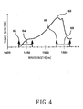
- maxim amplification 60 is obtained in wavelength region 68 which is shifted about 100 nm from wavelength region 64 of the pumping light to the long wavelength side, that is, when the frequency is increased by 13.3 THz.
- maximum amplification 60 is obtained from an optical signal 66 with a wavelength of 1530 nm.
- pumping light in the wavelength region 64 of 1430 nm to 1465 nm are incident in predetermined intervals and then an amplified optical signal is outputted in the wavelength region of 1530 nm to 1565 nm in an overlapped form Raman gain curves, one of which is indicated in FIG. 4.
- the zero dispersion wavelength is positioned in wavelength region 64 of a pumping light for amplifying an optical signal of the C-band wavelength region 68 as described above. Consequently, signal quality is deteriorated due to the four wave mixing (FWM).
- FWM four wave mixing
- the zero wavelength is positioned in the wavelength region of less than 1430 nm. Therefore, wide-band dispersion controlled optical fiber 100 enables Raman amplification of an optical signal in the C-band wavelength region in long distance transmission.
- a pumping light for Raman amplification of an optical signal in the L-band wavelength region uses the wavelength region of 1470 nm to 1505 nm. Therefore, wide-band dispersion controlled optical fiber 100 is controlled so that the zero dispersion is positioned in the wavelength region of less than 1430 nm.
- FIG. 5 shows the relationship between zero dispersion wavelengths and dispersion slopes at the zero dispersion wavelengths when dispersion values are in the range of 8 to 14 ps/nm/km in 1625 nm wavelength.
- reference numeral 71 indicates the case in which the dispersion values are controlled to 12.5 ps/nm/km or less at 1625 nm wavelength.
- Reference numeral 72 indicates the case in which the dispersion values are in the range of 12.5 to 13 ps/nm/km at 1625 nm wavelength.
- Reference numeral 73 indicates the case in which the dispersion values are in the range of 13 to 13.5 ps/pm/nm at 1625 nm wavelength. As shown in FIG. 5, as the dispersion slopes are lowered, the dispersion values are also lowered. Consequently, lowering the dispersion slopes is advantageous in long distance transmission using an optical signal of the L-band wavelength region.
- the dispersion slope in the zero dispersion wavelength is controlled to 0.074 ps/nm 2 /km or less
- the zero dispersion wavelength is positioned in the wavelength region of less than 1430 nm in order to control the dispersion values to 14 ps/nm/km or less at 1625 nm wavelength which is longer than the L-band wavelength region.
- the dispersion values are controlled to within a predetermined range at 1625 nm wavelength as described above, the long distance transmission of the L-band wavelength region becomes possible. This becomes possible by setting the distribution of refractive indexes of wide-band dispersion controlled optical fiber 100 in accordance with Equation 2 and Equation 3 as mentioned above.
- Equation 4 G ⁇ g A eff P pump L eff
- G indicates Raman gain efficiency
- g indicates Raman gain coefficient
- a eff indicates effective cross-section area
- P pump indicates output of pumping light
- L eff indicates effective distance
- the relative frequency shown in Fig. 6, means the difference of the frequency between optical signal and the pumping light.
- the reference numerals 81, 82 and 83 indicate Raman gain efficiency in the cases in which the effective cross-section area is 80 ⁇ m 2 , 70 ⁇ m 2 , and 60 ⁇ m 2 , respectively. From Equation 4 and FIG. 6, it can be seen that the Raman gain efficiency is enhanced as the effective cross-section area is reduced.
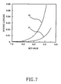
- FIG. 7 is a graph showing the relationship between an MCR value and bending loss of the wide-band dispersion controlled optical fiber.
- MCR value is a value which indicates the ratio between mode field diameter and cut-off wavelength. From the drawing, it can be seen that the bending loss abruptly increases as the MCR value exceeds a specific level. As shown in FIG. 7, if the MCR value exceeds a specific level, the bending loss at 1625 nm wavelength indicated by the curve 92 abruptly increases as compared to the bending loss at 1550 nm wavelength indicated by the curve 91. Therefore, in order to avoid the bending loss of the dispersion controlled optical fiber 100, it is preferable to control the MCR value to within a certain range.
- FIG. 8 is a graph showing optical loss of the dispersion controlled optical fiber with an MCR value controlled to within a certain range in regard to wavelength ranges.
- the optical fiber with an controlled MCR value exhibits optical loss 121 of about 0.196 dB/km at the wavelength 1550 nm, optical loss 122 about 0.208 dB/km at the wavelength of 1625 nm. If the deviation of optical loss in accordance with wavelength increases, it is required to provide apparatus in each wavelength region for compensation, amplification, etc., in order to maintain signal quality. Therefore, wide-band dispersion controlled optical fiber 100 is advantageous in long distance transmission because the deviation of optical loss according to wavelength is limited to 0.03 dB/km or less by the MCR value being controlled.
- the dispersion wavelength at 1430 nm wavelength is 0.9 ps/nm/km, the zero dispersion wavelength is located in the wavelength region below 1430 nm.
- the dispersion wavelength of the dispersion controlled optical fiber is measured as 1417.3 nm.
- a wide-band dispersion controlled optical fiber makes it possible to use optical signals in various wavelength regions in a wavelength division multiplexing mode communication network by controlling the position of zero dispersion wavelength, and enables long distance transmission by controlling dispersion slope and bending loss. Furthermore, there is an advantage in that it is possible to perform not only short distance transmission but also middle/long distance transmission using one type of optical fiber because the optical fiber is controlled to have negative dispersion values in the O-band wavelength region and positive dispersion values with small deviation in the C-band and L-band wavelength regions.
Landscapes
- Physics & Mathematics (AREA)
- Chemical & Material Sciences (AREA)
- Dispersion Chemistry (AREA)
- General Physics & Mathematics (AREA)
- Optics & Photonics (AREA)
- Optical Communication System (AREA)
- Optical Modulation, Optical Deflection, Nonlinear Optics, Optical Demodulation, Optical Logic Elements (AREA)
- Optical Fibers, Optical Fiber Cores, And Optical Fiber Bundles (AREA)
Applications Claiming Priority (2)
| Application Number | Priority Date | Filing Date | Title |
|---|---|---|---|
| KR2003003770 | 2003-01-20 | ||
| KR10-2003-0003770A KR100506311B1 (ko) | 2003-01-20 | 2003-01-20 | 광대역 분산 제어 광섬유 |
Publications (2)
| Publication Number | Publication Date |
|---|---|
| EP1439408A2 true EP1439408A2 (de) | 2004-07-21 |
| EP1439408A3 EP1439408A3 (de) | 2005-03-23 |
Family
ID=32588979
Family Applications (1)
| Application Number | Title | Priority Date | Filing Date |
|---|---|---|---|
| EP03018711A Ceased EP1439408A3 (de) | 2003-01-20 | 2003-08-25 | Breitbandig dispersionskontrollierte optische Faser |
Country Status (5)
| Country | Link |
|---|---|
| US (1) | US7003205B2 (de) |
| EP (1) | EP1439408A3 (de) |
| JP (1) | JP2004226964A (de) |
| KR (1) | KR100506311B1 (de) |
| CN (1) | CN1232842C (de) |
Families Citing this family (12)
| Publication number | Priority date | Publication date | Assignee | Title |
|---|---|---|---|---|
| US7020365B2 (en) * | 2002-08-29 | 2006-03-28 | Micron Technology, Inc. | Resistive heater for thermo optic device |
| US7120336B2 (en) * | 2002-08-29 | 2006-10-10 | Micron Technology, Inc. | Resonator for thermo optic device |
| US7006746B2 (en) * | 2002-08-29 | 2006-02-28 | Micron Technology, Inc. | Waveguide for thermo optic device |
| KR100693638B1 (ko) * | 2004-04-28 | 2007-03-14 | 엘에스전선 주식회사 | 구부림 강건형 광섬유 |
| US7187833B2 (en) * | 2004-04-29 | 2007-03-06 | Corning Incorporated | Low attenuation large effective area optical fiber |
| KR100735239B1 (ko) * | 2004-05-28 | 2007-07-03 | 삼성전자주식회사 | 메트로 망용 광섬유 |
| US7336877B2 (en) * | 2004-08-31 | 2008-02-26 | Corning Incorporated | Broadband optical fiber |
| US8503881B1 (en) | 2007-04-06 | 2013-08-06 | University Of Central Florida Research Foundation, Inc. | Systems for extending WDM transmission into the O-band |
| JP2011039109A (ja) * | 2009-08-06 | 2011-02-24 | Sumitomo Electric Ind Ltd | 光通信システム |
| WO2016017743A1 (ja) * | 2014-08-01 | 2016-02-04 | 株式会社フジクラ | 光ファイバ及びその製造方法 |
| US10067287B2 (en) | 2014-09-26 | 2018-09-04 | Fujikura Ltd. | Optical fiber and method of manufacturing the same |
| JP6306690B2 (ja) | 2014-09-26 | 2018-04-04 | 株式会社フジクラ | 光ファイバ |
Family Cites Families (21)
| Publication number | Priority date | Publication date | Assignee | Title |
|---|---|---|---|---|
| US5684909A (en) * | 1996-02-23 | 1997-11-04 | Corning Inc | Large effective area single mode optical waveguide |
| JPH1078524A (ja) | 1996-09-05 | 1998-03-24 | Shin Etsu Chem Co Ltd | 分散シフト光ファイバー |
| US5878182A (en) * | 1997-06-05 | 1999-03-02 | Lucent Technologies Inc. | Optical fiber having a low-dispersion slope in the erbium amplifier region |
| KR19990038607A (ko) * | 1997-11-06 | 1999-06-05 | 윤종용 | 다단계 코아 구조를 가지는 단일모드 광섬유 |
| WO1999034243A1 (en) * | 1997-12-30 | 1999-07-08 | Samsung Electronics Co., Ltd. | Single mode optical fiber |
| US5905838A (en) * | 1998-02-18 | 1999-05-18 | Lucent Technologies Inc. | Dual window WDM optical fiber communication |
| KR100636332B1 (ko) * | 1998-09-21 | 2006-10-19 | 피렐리 카비 에 시스테미 소시에떼 퍼 아찌오니 | 확장 파장 밴드용의 광파이버 |
| JP3928355B2 (ja) * | 1998-11-26 | 2007-06-13 | 住友電気工業株式会社 | 光ファイバ及びそれを含む光伝送システム |
| KR100342711B1 (ko) | 1998-12-17 | 2002-10-25 | 엘지전선 주식회사 | 삼중클래드의분산이동광섬유 |
| EP1141754B1 (de) * | 1998-12-18 | 2008-09-03 | Prysmian Cavi e Sistemi Energia S.r.l. | Optische faser für innerstädtische- und zugangs-netzwerksysteme |
| US6181717B1 (en) * | 1999-06-04 | 2001-01-30 | Bandwidth 9 | Tunable semiconductor laser system |
| HK1044044B (zh) * | 1999-09-09 | 2008-05-09 | 株式会社藤仓 | 色散位移光纤 |
| CN1206551C (zh) * | 1999-09-27 | 2005-06-15 | 住友电气工业株式会社 | 色散管理光纤、其制造方法、包含它的光通信系统及光纤母材 |
| RU2216755C2 (ru) * | 2000-02-25 | 2003-11-20 | Дзе Фурукава Электрик Ко., Лтд. | Оптическое волокно с низкой дисперсией и оптическая система передачи с использованием оптического волокна с низкой дисперсией |
| KR100349320B1 (ko) * | 2000-08-25 | 2002-08-21 | 엘지전선 주식회사 | 좁은 간격의 광채널을 이용한 파장분할 다중화 방식의광전송장치용 광섬유 |
| AU2001225460A1 (en) | 2000-09-27 | 2002-04-08 | Sterlite Optical Technologies Ltd. | Dispersion optimized fiber with low dispersion and optical loss |
| AU2002216647A1 (en) * | 2000-10-11 | 2002-04-22 | Corning Incorporated | Single mode optical waveguide fiber with reduced dispersion |
| CN1262856C (zh) * | 2001-04-30 | 2006-07-05 | 斯德莱特光学技术有限公司 | 具有低色散斜率的色散位移光纤 |
| NL1018338C2 (nl) | 2001-06-20 | 2002-12-30 | Draka Fibre Technology Bv | Optische vezel. |
| FR2828939B1 (fr) * | 2001-08-27 | 2004-01-16 | Cit Alcatel | Fibre optique pour un systeme de transmission a multiplexage en longueurs d'onde |
| FR2842610B1 (fr) * | 2002-07-18 | 2004-11-12 | Cit Alcatel | Fibre optique a gestion de dispersion |
-
2003
- 2003-01-20 KR KR10-2003-0003770A patent/KR100506311B1/ko not_active Expired - Fee Related
- 2003-08-05 US US10/634,699 patent/US7003205B2/en not_active Expired - Lifetime
- 2003-08-25 EP EP03018711A patent/EP1439408A3/de not_active Ceased
- 2003-08-26 JP JP2003301355A patent/JP2004226964A/ja active Pending
- 2003-08-28 CN CNB031577318A patent/CN1232842C/zh not_active Expired - Fee Related
Also Published As
| Publication number | Publication date |
|---|---|
| KR100506311B1 (ko) | 2005-08-05 |
| CN1517730A (zh) | 2004-08-04 |
| EP1439408A3 (de) | 2005-03-23 |
| US7003205B2 (en) | 2006-02-21 |
| CN1232842C (zh) | 2005-12-21 |
| JP2004226964A (ja) | 2004-08-12 |
| KR20040066643A (ko) | 2004-07-27 |
| US20040141705A1 (en) | 2004-07-22 |
Similar Documents
| Publication | Publication Date | Title |
|---|---|---|
| EP1083446B1 (de) | Optische übertragungsleitung, optische faser mit negativer dispersion für die optische übertragungsleitung und ein eine optische übertragungsleitung enthaltendes optisches übertragungssystem | |
| US6404967B2 (en) | Optical fiber and optical transmission line using the same | |
| US6603913B1 (en) | Single-mode optical fiber having multiple cladding regions for dispersion compensation | |
| US6466721B1 (en) | Dispersion compensating optical fiber and optical transmission line | |
| AU740596B2 (en) | Dispersion-shifted optical fiber | |
| US6862391B2 (en) | Optical transmission line, and optical fiber and dispersion compensating module employed in the same | |
| EP1396743B1 (de) | Dispersionskompensierende optische Faser | |
| EP1439408A2 (de) | Breitbandig dispersionskontrollierte optische Faser | |
| US6668120B2 (en) | Fiber for compensating the chromatic dispersion of an NZ-DSF having positive chromatic dispersion | |
| WO2000017683A1 (fr) | Fibre optique monomode a dispersion decalee optimisee pour les hauts debits | |
| AU783864B2 (en) | Dispersion compensation system | |
| US6754421B2 (en) | Optical fiber and optical transmission line using the optical fiber | |
| US6791744B2 (en) | Raman amplification optical fiber, optical fiber coil, raman amplifier, and optical communication system | |
| US20020067903A1 (en) | Fiber for compensating chromatic dispersion of a monomode fiber in band S | |
| US6522821B1 (en) | Dispersion-compensating optical fiber and optical transmission system including the same | |
| EP1191369A2 (de) | Optische Faser sowie Dispersionskompensator, optische Übertragungsleitung und optisches Übertragungssystem mit einer solchen Faser | |
| KR20040034588A (ko) | 고 분산슬로프를 달성하기위한 섬유 프로파일 | |
| US20040170366A1 (en) | Optical fiber and optical transmission line | |
| US7046889B2 (en) | Dispersion-shifted fiber | |
| US20030169986A1 (en) | Optical fiber, optical component, dispersion compensating fiber module, and optical communication system | |
| EP1372279A2 (de) | Dispersionskompensationseinheit und optisches Kommunikationssystem | |
| JP2001311848A (ja) | 光ファイバおよび光伝送システム |
Legal Events
| Date | Code | Title | Description |
|---|---|---|---|
| PUAI | Public reference made under article 153(3) epc to a published international application that has entered the european phase |
Free format text: ORIGINAL CODE: 0009012 |
|
| 17P | Request for examination filed |
Effective date: 20030825 |
|
| AK | Designated contracting states |
Kind code of ref document: A2 Designated state(s): AT BE BG CH CY CZ DE DK EE ES FI FR GB GR HU IE IT LI LU MC NL PT RO SE SI SK TR |
|
| AX | Request for extension of the european patent |
Extension state: AL LT LV MK |
|
| PUAL | Search report despatched |
Free format text: ORIGINAL CODE: 0009013 |
|
| AK | Designated contracting states |
Kind code of ref document: A3 Designated state(s): AT BE BG CH CY CZ DE DK EE ES FI FR GB GR HU IE IT LI LU MC NL PT RO SE SI SK TR |
|
| AX | Request for extension of the european patent |
Extension state: AL LT LV MK |
|
| AKX | Designation fees paid |
Designated state(s): DE FR GB |
|
| STAA | Information on the status of an ep patent application or granted ep patent |
Free format text: STATUS: THE APPLICATION HAS BEEN REFUSED |
|
| 18R | Application refused |
Effective date: 20070629 |