EP1439111A2 - Cast aluminum node for connecting vehicle frame members and method of manufacturing same - Google Patents
Cast aluminum node for connecting vehicle frame members and method of manufacturing same Download PDFInfo
- Publication number
- EP1439111A2 EP1439111A2 EP04250221A EP04250221A EP1439111A2 EP 1439111 A2 EP1439111 A2 EP 1439111A2 EP 04250221 A EP04250221 A EP 04250221A EP 04250221 A EP04250221 A EP 04250221A EP 1439111 A2 EP1439111 A2 EP 1439111A2
- Authority
- EP
- European Patent Office
- Prior art keywords
- node
- structural members
- insert
- securing
- inserts
- Prior art date
- Legal status (The legal status is an assumption and is not a legal conclusion. Google has not performed a legal analysis and makes no representation as to the accuracy of the status listed.)
- Withdrawn
Links
- 238000004519 manufacturing process Methods 0.000 title claims abstract description 12
- XAGFODPZIPBFFR-UHFFFAOYSA-N aluminium Chemical compound [Al] XAGFODPZIPBFFR-UHFFFAOYSA-N 0.000 title 1
- 229910052782 aluminium Inorganic materials 0.000 title 1
- 239000000463 material Substances 0.000 claims abstract description 40
- 238000005304 joining Methods 0.000 claims abstract description 18
- 238000000034 method Methods 0.000 claims description 24
- 238000005266 casting Methods 0.000 description 26
- 238000003466 welding Methods 0.000 description 17
- 239000000956 alloy Substances 0.000 description 6
- 239000007769 metal material Substances 0.000 description 6
- 239000000853 adhesive Substances 0.000 description 5
- 230000001070 adhesive effect Effects 0.000 description 5
- 230000000712 assembly Effects 0.000 description 5
- 238000000429 assembly Methods 0.000 description 5
- 230000000295 complement effect Effects 0.000 description 4
- 238000003780 insertion Methods 0.000 description 4
- 230000037431 insertion Effects 0.000 description 4
- 229910000838 Al alloy Inorganic materials 0.000 description 3
- 229910000851 Alloy steel Inorganic materials 0.000 description 3
- 239000000725 suspension Substances 0.000 description 3
Images









Classifications
-
- B—PERFORMING OPERATIONS; TRANSPORTING
- B22—CASTING; POWDER METALLURGY
- B22D—CASTING OF METALS; CASTING OF OTHER SUBSTANCES BY THE SAME PROCESSES OR DEVICES
- B22D19/00—Casting in, on, or around objects which form part of the product
- B22D19/04—Casting in, on, or around objects which form part of the product for joining parts
- B22D19/045—Casting in, on, or around objects which form part of the product for joining parts for joining tubes
-
- B—PERFORMING OPERATIONS; TRANSPORTING
- B62—LAND VEHICLES FOR TRAVELLING OTHERWISE THAN ON RAILS
- B62D—MOTOR VEHICLES; TRAILERS
- B62D23/00—Combined superstructure and frame, i.e. monocoque constructions
- B62D23/005—Combined superstructure and frame, i.e. monocoque constructions with integrated chassis in the whole shell, e.g. meshwork, tubes, or the like
-
- B—PERFORMING OPERATIONS; TRANSPORTING
- B62—LAND VEHICLES FOR TRAVELLING OTHERWISE THAN ON RAILS
- B62D—MOTOR VEHICLES; TRAILERS
- B62D29/00—Superstructures, understructures, or sub-units thereof, characterised by the material thereof
- B62D29/008—Superstructures, understructures, or sub-units thereof, characterised by the material thereof predominantly of light alloys, e.g. extruded
-
- Y—GENERAL TAGGING OF NEW TECHNOLOGICAL DEVELOPMENTS; GENERAL TAGGING OF CROSS-SECTIONAL TECHNOLOGIES SPANNING OVER SEVERAL SECTIONS OF THE IPC; TECHNICAL SUBJECTS COVERED BY FORMER USPC CROSS-REFERENCE ART COLLECTIONS [XRACs] AND DIGESTS
- Y10—TECHNICAL SUBJECTS COVERED BY FORMER USPC
- Y10T—TECHNICAL SUBJECTS COVERED BY FORMER US CLASSIFICATION
- Y10T29/00—Metal working
- Y10T29/49—Method of mechanical manufacture
- Y10T29/49616—Structural member making
-
- Y—GENERAL TAGGING OF NEW TECHNOLOGICAL DEVELOPMENTS; GENERAL TAGGING OF CROSS-SECTIONAL TECHNOLOGIES SPANNING OVER SEVERAL SECTIONS OF THE IPC; TECHNICAL SUBJECTS COVERED BY FORMER USPC CROSS-REFERENCE ART COLLECTIONS [XRACs] AND DIGESTS
- Y10—TECHNICAL SUBJECTS COVERED BY FORMER USPC
- Y10T—TECHNICAL SUBJECTS COVERED BY FORMER US CLASSIFICATION
- Y10T29/00—Metal working
- Y10T29/49—Method of mechanical manufacture
- Y10T29/49616—Structural member making
- Y10T29/49622—Vehicular structural member making
-
- Y—GENERAL TAGGING OF NEW TECHNOLOGICAL DEVELOPMENTS; GENERAL TAGGING OF CROSS-SECTIONAL TECHNOLOGIES SPANNING OVER SEVERAL SECTIONS OF THE IPC; TECHNICAL SUBJECTS COVERED BY FORMER USPC CROSS-REFERENCE ART COLLECTIONS [XRACs] AND DIGESTS
- Y10—TECHNICAL SUBJECTS COVERED BY FORMER USPC
- Y10T—TECHNICAL SUBJECTS COVERED BY FORMER US CLASSIFICATION
- Y10T29/00—Metal working
- Y10T29/49—Method of mechanical manufacture
- Y10T29/49826—Assembling or joining
-
- Y—GENERAL TAGGING OF NEW TECHNOLOGICAL DEVELOPMENTS; GENERAL TAGGING OF CROSS-SECTIONAL TECHNOLOGIES SPANNING OVER SEVERAL SECTIONS OF THE IPC; TECHNICAL SUBJECTS COVERED BY FORMER USPC CROSS-REFERENCE ART COLLECTIONS [XRACs] AND DIGESTS
- Y10—TECHNICAL SUBJECTS COVERED BY FORMER USPC
- Y10T—TECHNICAL SUBJECTS COVERED BY FORMER US CLASSIFICATION
- Y10T29/00—Metal working
- Y10T29/49—Method of mechanical manufacture
- Y10T29/49826—Assembling or joining
- Y10T29/49908—Joining by deforming
- Y10T29/49909—Securing cup or tube between axially extending concentric annuli
- Y10T29/49911—Securing cup or tube between axially extending concentric annuli by expanding inner annulus
Definitions
- the illustrated vehicular body and frame assembly 10 is a unitized space frame assembly that includes four different types of structural members that are secured to one another.
- the first type of structural member is a straight member, such as shown at 11.
- Straight members 11 are generally linear and elongated in shape.
- the second type of structural member is a curved member, such as shown at 12.
- Curved members 12 are non-linear and elongated in shape.
- the third type of structural member is a joint node, such as shown at 13.
- Joint nodes 13 are relatively short members that are provided to join adjacent structural members of the vehicle frame assembly 10 together at a joint.
- the fourth type of structural member is a member node, such as shown at 14.
- Member nodes 14 are relatively long structural members that are also provided to join adjacent members of the vehicle frame assembly 10 at a joint.
- the end portions 12a, 13a, and 14a of the structural members 12, 13, and 14 can secured to the associated mounting portions 40b by welds, such as shown at 43 in Figs. 10 and 11.
- the welds 43 may be created by any desired process, such as by laser welding or magnetic pulse welding.
- the use of conventional welding techniques to secure the structural members 12, 13, and 14 to the associated mounting portions 40b is facilitated when the structural members 12, 13, and 14 and the mounting portion 40b are all formed from the same metallic material.
- Figs. 21 and 22 show a similar structure and process, wherein a side frame structure for a vehicle, indicated generally at 70 in Fig. 22, is formed from a plurality of structural members 71 that are joined together by nodes 72 that are cast about the end portions thereof.
- a generally C-shaped mounting insert 94 is disposed within the generally C-shaped recess 93 on the front side of the node 90.
- the mounting insert 94 and the node 90 can be secured together by any conventional means. For example, if the mounting insert 94 and the node 90 are formed from the same material, then they can be secured together by conventional welding techniques, such as described above. If, on the other hand, mounting insert 94 and the node 90 are formed from different materials, then they can be secured together by adhesives, mechanical fasteners, and the like, as also described above.
- the illustrated structural member 103 has an end portion 103a that is sized to cooperate with the associated mounting insert 102.
- the end portion 103a may be the portion of the structural member 103 that was engaged by the end feed cylinders of the hydroforming machine during the hydroforming operation.
- the end portion 103a of the structural member 103 can be positioned on the associated mounting insert 102 and moved relative to the body portion 101 of the node both in a lateral direction, as indicated by the arrow 104, and in a rotational direction, as indicated by the arrow 105, until a desired relative orientation is achieved. Thereafter, the end portion 103a of the structural member 103 can be secured to the associated mounting insert 102 in the manner described above.
Landscapes
- Engineering & Computer Science (AREA)
- Mechanical Engineering (AREA)
- Chemical & Material Sciences (AREA)
- Combustion & Propulsion (AREA)
- Transportation (AREA)
- Architecture (AREA)
- Structural Engineering (AREA)
- Body Structure For Vehicles (AREA)
Abstract
Description
- This invention relates in general to the manufacture and assembly of vehicle frame members and in particular to a method and apparatus for forming nodes that facilitate the connection of frame members.
- Many land vehicles in common use, such as automobiles, vans, and trucks, include a body and frame assembly that is supported upon a plurality of ground-engaging wheels by a resilient suspension system. The structures of known body and frame assemblies can be divided into two general categories, namely, separate and unitized. In a typical separate body and frame assembly, the structural components of the body portion and the frame portion of the vehicle are separate and independent from one another. When assembled, the frame portion of the assembly is resiliently supported upon the vehicle wheels by the suspension system and serves as a platform upon which the body portion of the assembly and other components of the vehicle can be mounted. Separate body and frame assemblies of this general type are found in most older vehicles, but remain in common use today for many relatively large or specialized use modem vehicles, such as large vans, sport utility vehicles, and trucks. In a typical unitized body and frame assembly, sometimes referred to as a space frame assembly, the structural components of the body portion and the frame portion are combined into an integral unit that is resiliently supported upon the vehicle wheels by the suspension system. Unitized body and frame assemblies of this general type are found in many relatively small modem vehicles, such as automobiles and minivans.
- Most known vehicular body and frame assemblies are formed from a plurality of individual structural members that are permanently joined to one another. In the past, the various structural members have been secured directly to one another to form the vehicular body and frame assembly. More recently, it has been proposed to manufacture a vehicular body and frame assembly by providing a plurality of structural members and a plurality of nodes. The ends of the structural members are secured to mounting portions provided on the nodes to form the vehicular body and frame assembly. The known methods for manufacturing a vehicular body and frame assembly have been satisfactory when all of the structural members thereof are formed from the same material. However, it has been found to be desirable to form some or all of the structural members of the vehicular body and frame assembly from different materials. Thus, it would be desirable to provide an improved method of manufacturing a node for joining a plurality of structural members together, such as in a vehicular body and frame assembly, that is well suited for joining structural members that are formed from differing materials.
- This invention relates to an improved method of manufacturing a node for joining a plurality of structural members together, such as in a vehicular body and frame assembly, is well suited for joining structural members that are formed from differing materials. An insert is provided having a node securing portion and a mounting portion that is adapted to have a structural member secured thereto. A node is formed about the node securing portion of the insert for joining a plurality of structural members together. The insert can be formed from a first material, while the node can be formed from a second material that is different from the first material. The insert can be provided with a node securing portion having at least one aperture or protrusion formed therein, and the node can be formed within or about the aperture or protrusion. A plurality of inserts can be provided, each having a node securing portion and a mounting portion, and the node can be formed about each of the node securing portions of the inserts. The structural members can be secured to the mounting portions of the inserts before the node is formed.
- Various objects and advantages of this invention will become apparent to those skilled in the art from the following detailed description of the preferred embodiments, when read in light of the accompanying drawings.
-
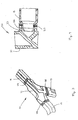
- Fig. 1 is a perspective view of a vehicle frame assembly that is formed from a plurality of structural members and includes a pair of nodes in accordance with a first embodiment of this invention for joining two or more of such structural members together.
- Fig. 2 is an enlarged exploded perspective view of one of the nodes and the end portions of several of the structural members illustrated in Fig. 1.
- Fig. 3 is an enlarged perspective view of the node and the end portions of the structural members illustrated in Fig. 2 shown assembled.
- Fig. 4 is a sectional elevational view of a portion of the node and the end portion of one of the structural members illustrated in Fig. 3.
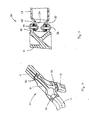
- Fig. 5 is an enlarged exploded perspective view of a node in accordance with a second embodiment of this invention and the end portions of several of the structural members illustrated in Fig. 1.
- Fig. 6 is an enlarged perspective view of the node and the end portions of the structural members illustrated in Fig. 5 shown assembled.
- Fig. 7 is a sectional elevational view of a portion of the node and the end portion of one of the structural members illustrated in Fig. 6.
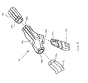
- Fig. 8 is an enlarged perspective view of a plurality of inserts that can be used to form a third embodiment of a node for joining two or more of the structural members illustrated in Fig. 1 together.
- Fig. 9 is an enlarged exploded perspective view of a third embodiment of a node after it has been formed about the inserts illustrated in Fig. 8, and further including the end portions of several of the structural members illustrated in Fig. 1.
- Fig. 10 is an enlarged perspective view of the node and the end portions of the structural members illustrated in Fig. 9 shown assembled.
- Fig. 11 is a sectional elevational view of a portion of the node and the end portion of one of the structural members illustrated in Fig. 10.
- Fig. 12 is an enlarged perspective view of a plurality of inserts that can be used to form a fourth embodiment of a node for joining two or more of the structural members illustrated in Fig. 1 together.
- Fig. 13 is a sectional elevational view of a portion of a fourth embodiment of a node and the end portion of one of the structural members illustrated in Fig. 1.
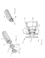
- Fig. 14 is an exploded perspective view of an end portion of one of the structural members illustrated in Fig. 1 and a pair of insert cups that can be used to form a fifth embodiment of a node for joining two or more of the structural members illustrated in Fig. 1 together.
- Fig. 15 is a perspective view of the end portion of the structural member and the pair of insert cups illustrated in Fig. 14 shown assembled.
- Fig. 16 is a sectional elevational view of the end portion of the structural member and the pair of insert cups illustrated in Fig. 15.
- Fig. 17 is a perspective view of a fifth embodiment of the node after it has been formed about the end portion of the structural member and the pair of insert cups illustrated in Figs. 14, 15, and 16, and further about the end portions of several others of the structural members illustrated in Fig. 1.
- Fig. 18 is a sectional elevational view of a portion of the fifth embodiment of the node illustrated in Fig. 17 and the end portion of the structural member illustrated in Fig. 16.
- Fig. 19 is an exploded perspective view of a plurality of the structural members illustrated in Fig. 1 prior to being joined together by a plurality of nodes to form a vehicle frame sub-assembly.
- Fig. 20 is a perspective view of the vehicle sub-frame assembly illustrated in Fig. 19 shown assembled.
- Fig. 21 is an exploded side elevational view of a plurality of the structural members prior to being joined together by a plurality of nodes to form a vehicle side frame assembly.
- Fig. 22 is a side elevational view of the vehicle side frame assembly illustrated in Fig. 21 shown assembled.
- Fig. 23 is a perspective view of a sixth embodiment of a node that can be used to join a plurality of structural members together to form a vehicle frame assembly.
- Fig. 24 is a perspective view of a pair of structural members that are connected together by the sixth embodiment of the node illustrated in Fig. 23.
- Fig. 25 is a perspective view of a seventh embodiment of a node that can be used to join a plurality of structural members together to form a vehicle frame assembly.
- Fig. 26 is a perspective view of an eighth embodiment of a node that can be used to join a plurality of structural members together to form a vehicle frame assembly.
- Fig. 27 is a perspective view of a pair of structural members that are connected together by the eighth embodiment of the node illustrated in Fig. 26.
- Fig. 28 is a perspective view of a ninth embodiment of a node, a plurality of inserts, and an end portion of a structural member.
-
- Referring now to the drawings, there is illustrated in Fig. 1 a vehicular body and frame assembly, indicated generally at 10, in accordance with this invention. The illustrated vehicular body and
frame assembly 10 is, in large measure, conventional in the art and is intended merely to illustrate one environment in which this invention may be used. Thus, the scope of this invention is not intended to be limited for use with the specific structure for the vehicular body andframe assembly 10 illustrated in Fig. 1 or with vehicular body and frame assemblies in general. On the contrary, as will become apparent below, this invention may be used in any desired environment for the purposes described below. - The illustrated vehicular body and
frame assembly 10 is a unitized space frame assembly that includes four different types of structural members that are secured to one another. The first type of structural member is a straight member, such as shown at 11.Straight members 11 are generally linear and elongated in shape. The second type of structural member is a curved member, such as shown at 12. Curvedmembers 12 are non-linear and elongated in shape. The third type of structural member is a joint node, such as shown at 13.Joint nodes 13 are relatively short members that are provided to join adjacent structural members of thevehicle frame assembly 10 together at a joint. The fourth type of structural member is a member node, such as shown at 14.Member nodes 14 are relatively long structural members that are also provided to join adjacent members of thevehicle frame assembly 10 at a joint. - In the illustrated embodiment, each of the
structural members structural members structural members structural members vehicle frame assembly 10. This can be accomplished, for example, by forming some end portions of the variousstructural members structural members - The illustrated
vehicle frame assembly 10 also includes two nodes in accordance with a first embodiment of this invention, each indicated generally at 20. Each of thenodes 20 is provided for joining two or more of thestructural members nodes 20 is provided for securing one of thecurved members 12, one of thejoint nodes 13, and one of themember nodes 14 together at a joint. However, it will be appreciated that thenodes 20 can be used to join any number of any of thestructural members vehicle frame assembly 10 together at a variety of different joints. - The structure of one of the
nodes 20 is illustrated in detail in Figs. 2, 3, and 4. As shown therein, the illustratednode 20 includes abody portion 21 having a plurality of mountingportions node 20 can be manufactured in any desired manner, such as by casting. As best shown in Figs. 2 and 4, the mountingportions end portions structural members end portions structural members portions node 20, as shown in Figs. 3 and 4. Preferably, the outer surfaces of theend portions portions end portions portion node 20. Preferably, theend portions structural members end portions end portions portions illustrated end portions structural members portions welds 25 may be created by any desired process, such as by laser welding or magnetic pulse welding. The use of conventional welding techniques to secure thestructural members portions structural members node 20 are all formed from the same metallic material. - However, in some instances, it may be desirable to secure the
structural members portions structural members node 20 are formed from different metallic or non-metallic materials. In these instances, a second embodiment of one of the nodes, indicated generally at 30 in Figs. 5, 6, and 7, can be used. As shown therein, the illustratednode 30 includes abody portion 31 having a plurality of mountingportions node 30 can be manufactured in any desired manner, such as by casting. As best shown in Figs. 5 and 7, the mountingportions end portions structural members end portions structural members portions node 30, as shown in Figs. 6 and 7. Preferably, the outer surfaces of theend portions portions end portions portion node 30. Preferably, theend portions structural members end portions end portions portions end portions structural members portions rivets 36 or similar fasteners, such as shown at 36 in Figs. 6 and 7. Preferably, theend portions node 30 may be formed such that when theend portions portions end portions portions - Fig. 8 is an enlarged exploded perspective view of a plurality of inserts, indicated generally at 40, that can be used to form a third embodiment of a node, indicated generally at 41 in Figs. 9, 10, and 11, for joining two or more of the
structural members node securing portion 40a and a mountingportion 40b. Each of thenode securing portions 40a has one or more apertures 40c formed therethrough. Preferably, theinserts 40 are roll-formed and swaged to a desired shape, although and desired method of manufacture can be used. To manufacture thenode 41, theinserts 40 are initially positioned in desired positions relative to one another, such as shown in Fig. 8. Such relative positioning can, for example, be accomplished by providing a die (not shown), such as a conventional casting die, having cavities formed therein for respectively supporting theinserts 40 in the desired relative orientation. Then, the casting die is filled with a conventional casting material that extends about each of thenode securing portions 40a of theinserts 40, including into the apertures 40c formed through suchnode securing portions 40a. Preferably, the casting material does not extend about the mountingportions 40b of theinserts 40. The casting material is subsequently hardened and removed from the casting die to provide thenode 41 including abody portion 42 having each of theinserts 40 secured thereto, as shown in Fig. 9. The casting process is particularly well suited when theinserts 40 and thebody portion 42 of thenode 41 are formed from a different materials. For example, theinserts 40 may be formed from a steel alloy material, while thebody portion 42 of thenode 41 may be formed from an aluminum alloy material. By allowing the casting material to extend into the apertures 40c formed through thenode securing portions 40a of theinserts 40, a secure mechanical connection is provided between thebody portion 42 of thenode 40 and theinserts 40, especially when differing materials are used. - Similar to the mounting
portions portions 40b are hollow and are formed having cross sectional shapes that are complementary to endportions structural members end portions structural members portions 40b of thenode 41, as shown in Figs. 10 and 11. Preferably, the outer surfaces of theend portions portions 40b. However, theend portions portion 40b of thenode 41. Theend portions structural members portions 40b by welds, such as shown at 43 in Figs. 10 and 11. Thewelds 43 may be created by any desired process, such as by laser welding or magnetic pulse welding. The use of conventional welding techniques to secure thestructural members portions 40b is facilitated when thestructural members portion 40b are all formed from the same metallic material. - Fig. 12 is an enlarged exploded perspective view of a plurality of inserts, indicated generally at 50, that can be used to form a fourth embodiment of a node, indicated generally at 51 in Fig. 13, for joining two or more of the
structural members node securing portion 50a and a mountingportion 50b. Each of thenode securing portions 50a has one or more outwardly extendingprotrusions 50c formed thereon. To manufacture thenode 51, theinserts 50 are initially positioned in desired positions relative to one another, such as shown in Fig. 12. Such relative positioning can, for example, be accomplished by providing a die (not shown), such as a conventional casting die, having cavities formed therein for respectively supporting theinserts 50 in the desired relative orientation. Then, the casting die is filled with a conventional casting material that extends about each of thenode securing portions 50a of theinserts 50, including about theprotrusions 50c formed on suchnode securing portions 50a. Preferably, the casting material does not extend about the mountingportions 50b of theinserts 50. The casting material is subsequently hardened and removed from the casting die to provide thenode 51 including abody portion 52 having each of theinserts 50 secured thereto, as shown in Fig. 13. The casting process is particularly well suited when theinserts 50 and thebody portion 52 of thenode 51 are formed from a different materials. For example, theinserts 50 may be formed from a steel alloy material, while thebody portion 52 of thenode 51 may be formed from an aluminum alloy material. By allowing the casting material to extend about theprotrusions 50c formed on thenode securing portions 50a of theinserts 50, a secure mechanical connection is provided between thebody portion 52 of thenode 51 and theinserts 50, especially when differing materials are used. - Similar to the mounting
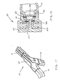
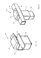
portions 40b discussed above, the mountingportions 50b are hollow and are formed having cross sectional shapes that are complementary to endportions structural members end portions structural members portions 50b of thenode 51, as shown in Fig. 13. Preferably, the outer surfaces of theend portions portions 50b. However, theend portions portion 50b of thenode 51. Theend portions structural members portions 50b by welds, such as shown at 53 in Fig. 13. Thewelds 53 may be created by any desired process, such as by laser welding or magnetic pulse welding. The use of conventional welding techniques to secure thestructural members portions 50b is facilitated when thestructural members portion 50b are all formed from the same metallic material. - Figs. 14, 15, and 16 illustrate an end portion of one of the
structural members 14 illustrated in Fig. 1 and a pair of insert cups, indicated generally at 60 and 61, that can be used to form a fifth embodiment of a node 62 (see Figs. 17 and 18) for joining two or more of thestructural members insert cup 60 includes a cup-shapedbase portion 60a and an outwardly extendingflange portion 60b. Similarly, theinsert cup 61 includes a cup-shapedbase portion 61a and an outwardly extending flange portion 61b. The insert cups 60 and 61 can be formed in any desired manner, such as by drawing or stamping a flat sheet of material into a desired configuration. Preferably, the cup-shapedbase portion 60a of thefirst insert cup 60 is sized to fit snugly within the inner surface of theend portion 14a of thestructural member 14, as shown in Fig. 16. Thus, thefirst insert cup 60 can be secured to theend portion 14a of thestructural member 14, such as by aweld 63. Similarly, the cup-shapedbase portion 61 a of thesecond insert cup 60 is sized to fit snugly within the cup-shapedbase portion 60a of thefirst insert cup 60, as also shown in Fig. 16. Thus, thesecond insert cup 61 can be secured to thefirst insert cup 60, such as by aweld 64. Thewelds end portion 14a of thestructural member 14 is facilitated when the insert cups 60 and 61 and thestructural member 14 are all formed from the same metallic material. - To manufacture the
node 62, the end of thestructural member 14 and the insert cups 60 and 61 are positioned in a die (not shown), such as a conventional casting die, having a cavity formed therein. At the same time, the ends of the other structural members, such as thestructural members end portions 12a and 13a thereof) are also positioned in the die in a desired relative orientation relative to one another. Then, the casting die is filled with a conventional casting material that extends about the ends of thestructural members flange portions 60b and 61b, as shown in Figs. 17 and 18. It will be appreciated that the insert cups 60 and 61 prevent casting material from undesirably entering within the interiors of the respectivestructural members node 62 including abody portion 65 having theend portions body portion 65 of thenode 62 is formed from a different material than thestructural members body portion 65 of thenode 62 may be formed from an aluminum alloy material, while thestructural members flange portions 60b and 61b of the insert cups 60 and 61, respectively, a secure mechanical connection is provided between thebody portion 65 of thenode 62 and thestructural members - It should be appreciated that the insert cups 60 and 61 are intended to be representative of any desired structure or structures that may be secured to the end portions of the structural members to facilitate the securement thereof to the
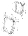
node 62. For example, the end portions of the structural members may have either or both of theinserts - Fig. 19 is an exploded perspective view of a plurality of structural members, such as a plurality of the
straight members 11 illustrated in Fig. 1, prior to being joined together by a plurality of thenodes 62 illustrated in Figs. 17 and 18 to form a vehicle frame sub-assembly 66. As shown therein, each of thestructural members 11 has a pair of the insert cups 60 and 61 secured to the end portions thereof in the manner discussed above. Thestructural members 11 can be disposed within the respective cavities of a multiple cavity die (a four cavity die, in the illustrated embodiment) such that a pair of adjacent end portions of thestructural members 11 extends within each of the die cavities (which are indicated by the dotted lines in Fig. 19). Then, thenodes 62 can be cast about the end portions thereof in the manner described above to form the vehicle sub-frame assembly illustrated in Fig. 20. Figs. 21 and 22 show a similar structure and process, wherein a side frame structure for a vehicle, indicated generally at 70 in Fig. 22, is formed from a plurality ofstructural members 71 that are joined together bynodes 72 that are cast about the end portions thereof. - Fig. 23 is a perspective view of a sixth embodiment of a node, indicated generally at 80, that can be used to join a plurality of structural members together to form the
vehicle frame assembly 10 illustrated in Fig. 1. Thenode 80 includes ahollow base portion 81 and an upstanding L-shapedportion 82. Thehollow base portion 81 is closed on the back side thereof. As a result, aclosed pocket 83 is defined within thebase portion 81 of thenode 80. Because the back side of thebase portion 81 is closed, thepocket 83 can be accessed only through the bottom side of thenode 80. Thebase portion 81 and the upstanding L-shapedportion 82 of thenode 80 define a generally C-shapedrecess 84 on the front side of thenode 80. - Fig. 24 is a perspective view of a pair of
structural members node 80 illustrated in Fig. 23. As shown therein, an end portion of the firststructural member 85 is inserted within thepocket 83 formed in thebase portion 81 of thenode 80. Thenode 80 and the end portion of the firststructural member 85 can be secured together by any conventional means. For example, if thenode 80 and the end portion of the firststructural member 85 are formed from the same material, then they can be secured together by conventional welding techniques, such as described above. If, on the other hand, thenode 80 and the end portion of the firststructural member 85 are formed from different materials, then they can be secured together by adhesives, mechanical fasteners, and the like, as also described above. A portion of a secondstructural member 86 extends through the generally C-shapedrecess 84 defined on the front side of thenode 80. Thenode 80 and the portion of the secondstructural member 86 can also be secured together by any conventional means, as described above. - Fig. 25 is a perspective view of a seventh embodiment of a node, indicated generally at 80', that can be used to join a plurality of structural members together to form the
vehicle frame assembly 10 illustrated in Fig. 1. The node 80' is similar to thenode 80 and includes a hollow base portion 81' and an upstanding L-shaped portion 82'. In this embodiment, the hollow base portion 81' is opened on the back side thereof. As a result, an opened pocket 83' is defined within the base portion 81' of the node 80'. Because the back side of the base portion 81' is opened, the pocket 83' can be accessed from both the bottom and back sides of the node 80'. The base portion 81' and the upstanding L-shaped portion 82' of the node define a generally C-shaped recess 84' on the front side of the node 80'. The first and secondstructural members - Fig. 26 is a perspective view of an eighth embodiment of a node, indicated generally at 90, that can be used to join a plurality of structural members together to form the
vehicle frame assembly 10 illustrated in Fig. 1. Thenode 90 includes ahollow base portion 91 and an upstanding L-shapedportion 92. Thehollow base portion 91 can be either closed or opened on the back side thereof, as discussed above. As a result, a pocket (not shown) is defined within thebase portion 91 of thenode 90. Thebase portion 91 and the upstanding L-shapedportion 92 of thenode 90 define a generally C-shapedrecess 93 on the front side of thenode 90. A generally C-shaped mountinginsert 94 is disposed within the generally C-shapedrecess 93 on the front side of thenode 90. The mountinginsert 94 and thenode 90 can be secured together by any conventional means. For example, if the mountinginsert 94 and thenode 90 are formed from the same material, then they can be secured together by conventional welding techniques, such as described above. If, on the other hand, mountinginsert 94 and thenode 90 are formed from different materials, then they can be secured together by adhesives, mechanical fasteners, and the like, as also described above. - Fig. 27 is a perspective view of a pair of
structural members node 90 illustrated in Fig. 26. As shown therein, an end portion of the firststructural member 95 is inserted within the pocket formed in thebase portion 91 of thenode 90. Thenode 90 and the end portion of the firststructural member 95 can be secured together by any conventional means. For example, if thenode 90 and the end portion of the firststructural member 95 are formed from the same material, then they can be secured together by conventional welding techniques, such as described above. If, on the other hand, thenode 90 and the end portion of the firststructural member 95 are formed from different materials, then they can be secured together by adhesives, mechanical fasteners, and the like, as also described above. A portion of a secondstructural member 96 extends through the generally C-shaped mountinginsert 94 secured to thenode 90. The C-shaped mountinginsert 94 and the portion of the secondstructural member 96 can also be secured together by any conventional means, as described above. - Fig. 28 is a perspective view of a ninth embodiment of a node, indicated generally at 100, that can be used to form a portion of the
vehicle frame assembly 10 illustrated in Fig. 1. In this embodiment, thenode 100 includes abody portion 101 having a plurality of mountinginserts 102 secured thereto. Thebody portion 101 of thenode 100 can be cast about the mountinginserts 102 as described above, particularly if thebody portion 101 of thenode 100 and the mountinginsert 102 are formed from different materials. However, the mountinginserts 102 can be secured to thebody portion 101 of thenode 100 in any desired manner. Astructural member 103 is adapted to be secured to one of the mountinginserts 102 in the same general manner as described above. The illustratedstructural member 103 has anend portion 103a that is sized to cooperate with the associated mountinginsert 102. For example, if thestructural member 103 is hydroformed to a desired shape, then theend portion 103a may be the portion of thestructural member 103 that was engaged by the end feed cylinders of the hydroforming machine during the hydroforming operation. Theend portion 103a of thestructural member 103 can be positioned on the associated mountinginsert 102 and moved relative to thebody portion 101 of the node both in a lateral direction, as indicated by thearrow 104, and in a rotational direction, as indicated by thearrow 105, until a desired relative orientation is achieved. Thereafter, theend portion 103a of thestructural member 103 can be secured to the associated mountinginsert 102 in the manner described above. - In accordance with the provisions of the patent statutes, the principle and mode of operation of this invention have been explained and illustrated in its preferred embodiments. However, it must be understood that this invention may be practiced otherwise than as specifically explained and illustrated without departing from its spirit or scope.
Claims (10)
- A method of manufacturing a node for joining a plurality of structural members together comprising the steps of:(a) providing an insert having a node securing portion and a mounting portion that is adapted to have a structural member secured thereto; and(b) forming a node about the node securing portion of the insert for joining a plurality of structural members together.
- The method defined in Claim 1 wherein said step (a) is performed by forming the insert from a first material; and wherein said step (b) is performed by forming the node from a second material that is different from the first material.
- The method defined in Claim 1 wherein said step (a) is performed by providing the insert with a node securing portion having at least one aperture formed therein; and wherein said step (b) is performed by forming a portion of the node within the at least one aperture.
- The method defined in Claim 1 wherein said step (a) is performed by providing the insert with a node securing portion having at least one protrusion formed thereon; and wherein said step (b) is performed by forming a portion of the node about the at least one protrusion.
- The method defined in Claim 1 including the further step (c) of securing a first structural member to the mounting portion of the insert and securing a second structural member to the node.
- The method defined in Claim 5 wherein said step (c) is performed by initially moving the first structural member both in a lateral direction and in a rotational direction relative to the insert until a desired relative orientation is achieved and then securing the first structural member to the insert.
- The method defined in Claim 1 wherein said step (a) is performed by providing a plurality of inserts, each of the inserts having a node securing portion and a mounting portion that is adapted to have a structural member secured thereto; and wherein said step (b) is performed by forming a node about each of the node securing portions of the inserts.
- The method defined in Claim 7 including the further step (c) of securing a structural member to the mounting portion of each of the inserts.
- The method defined in Claim 1 wherein said step (a) is performed by securing the mounting portion of the insert to a structural member before performing said step (b).
- The method defined in Claim 1 wherein said step (a) is performed by securing the mounting portion of the insert to close an open end of a hollow structural member before performing said step (b).
Applications Claiming Priority (2)
| Application Number | Priority Date | Filing Date | Title |
|---|---|---|---|
| US44057303P | 2003-01-16 | 2003-01-16 | |
| US440573P | 2003-01-16 |
Publications (2)
| Publication Number | Publication Date |
|---|---|
| EP1439111A2 true EP1439111A2 (en) | 2004-07-21 |
| EP1439111A3 EP1439111A3 (en) | 2006-07-05 |
Family
ID=32595355
Family Applications (1)
| Application Number | Title | Priority Date | Filing Date |
|---|---|---|---|
| EP04250221A Withdrawn EP1439111A3 (en) | 2003-01-16 | 2004-01-16 | Cast aluminum node for connecting vehicle frame members and method of manufacturing same |
Country Status (6)
| Country | Link |
|---|---|
| US (2) | US7322106B2 (en) |
| EP (1) | EP1439111A3 (en) |
| JP (1) | JP2004217207A (en) |
| CN (1) | CN1541880A (en) |
| CA (1) | CA2455286A1 (en) |
| MX (1) | MXPA04000445A (en) |
Cited By (3)
| Publication number | Priority date | Publication date | Assignee | Title |
|---|---|---|---|---|
| EP1571070A3 (en) * | 2004-03-05 | 2006-04-12 | DaimlerChrysler AG | Composite part |
| EP1902931A1 (en) * | 2006-09-22 | 2008-03-26 | Audi Ag | Bodywork module for a motor vehicle and its mounting system |
| US20150020388A1 (en) * | 2013-07-22 | 2015-01-22 | GM Global Technology Operations LLC | Uniframe and method of making the same |
Families Citing this family (70)
| Publication number | Priority date | Publication date | Assignee | Title |
|---|---|---|---|---|
| GB2387154B (en) * | 2000-04-05 | 2004-06-09 | Lotus Car | A method of manufacture of an automobile structure |
| MXPA04000445A (en) * | 2003-01-16 | 2004-11-12 | Dana Corp | Cast aluminum node for connecting vehicle frame members and method of manufacturing same. |
| WO2005021361A1 (en) * | 2003-08-27 | 2005-03-10 | Thyssenkrupp Steel Ag | Post in a carrier structure of a motor vehicle in a spaceframe style |
| US8899624B2 (en) * | 2005-05-19 | 2014-12-02 | Magna International Inc. | Controlled pressure casting |
| US8496258B2 (en) * | 2003-10-20 | 2013-07-30 | Magna International Inc. | Hybrid component |
| US8163116B2 (en) * | 2006-05-09 | 2012-04-24 | Zephyros, Inc. | Joints and a system and method of forming the joints |
| US8162388B2 (en) * | 2006-07-03 | 2012-04-24 | Ford Global Technologies, Llc | Multiple tube body side construction for automobiles |
| US7441819B2 (en) * | 2006-09-26 | 2008-10-28 | Ford Global Technologies, Llc | Tubular structural joint for automotive front end |
| DE102006055506A1 (en) * | 2006-11-24 | 2008-05-29 | Dr.Ing.H.C. F. Porsche Ag | Cross member, in particular a cockpit cross member |
| US20080258449A1 (en) * | 2007-04-17 | 2008-10-23 | Ronald Allen Wehner | Retention arrangement for vehicle front-end module |
| USD585788S1 (en) * | 2007-05-10 | 2009-02-03 | John Burns | Off-road vehicle frame |
| USD586260S1 (en) * | 2007-05-10 | 2009-02-10 | John Burns | Off-road vehicle frame |
| USD586261S1 (en) * | 2007-05-10 | 2009-02-10 | John Burns | Off-road vehicle frame |
| USD586695S1 (en) * | 2007-05-10 | 2009-02-17 | John Burns | Off-road vehicle frame |
| USD585789S1 (en) * | 2007-05-10 | 2009-02-03 | John Burns | Off-road vehicle frame |
| USD585790S1 (en) * | 2007-05-10 | 2009-02-03 | John Burns | Off-road vehicle frame |
| USD586696S1 (en) * | 2007-10-23 | 2009-02-17 | John Burns | Off-road vehicle frame |
| DE102008003719A1 (en) * | 2008-01-09 | 2009-07-16 | Man Nutzfahrzeuge Ag | Skeleton construction of a bus |
| FR2985496B1 (en) * | 2008-03-10 | 2015-02-06 | Plastic Omnium Cie | ASSEMBLY OF AN OPENING PANEL AND REINFORCING ELEMENTS. |
| USD638333S1 (en) * | 2008-08-12 | 2011-05-24 | Rma Automotive Co., Ltd. | Vehicle |
| US8640814B2 (en) | 2009-06-15 | 2014-02-04 | Polaris Industries Inc. | Side-by-side vehicle |
| US8210554B2 (en) | 2009-07-09 | 2012-07-03 | Trek Bicycle Corporation | Bicycle frame having a multiple step and lap joint |
| US8262155B2 (en) * | 2009-12-06 | 2012-09-11 | Honda Motor Co., Ltd. | Overmolded joint for beam assembly |
| CN102009697A (en) * | 2010-06-13 | 2011-04-13 | 贾秉成 | Connection structure of vehicle frame |
| US9650078B2 (en) | 2011-02-11 | 2017-05-16 | Polaris Industries Inc. | Side-by-side all terrain vehicle |
| EP2511084B1 (en) * | 2011-04-14 | 2014-11-12 | Magna Steyr Fahrzeugtechnik AG & Co KG | Fibre-reinforced plastic node element and method for producing and using same |
| US20120273539A1 (en) * | 2011-04-28 | 2012-11-01 | GM Global Technology Operations LLC | Support structure and method of manufacturing the same |
| US8833832B2 (en) | 2011-08-16 | 2014-09-16 | Ford Global Technologies, Llc | Node for connecting vehicle body portions |
| KR101755706B1 (en) * | 2011-09-05 | 2017-07-10 | 현대자동차주식회사 | Cowl cross structure |
| DE102012101389A1 (en) * | 2012-02-21 | 2013-08-22 | Martinrea Honsel Germany Gmbh | Manufacturing composite component from metallic material, comprises casting a second metallic part on a first metallic part to form a contact zone, and drawing a weld seam along the contact zone |
| GB2504671A (en) * | 2012-08-03 | 2014-02-12 | Bae Systems Plc | Alignment device, and method of alignment using an alignment device |
| DE112013005135A5 (en) * | 2012-10-24 | 2015-07-16 | Ksm Castings Group Gmbh | Modular system for the rear frame of a motor vehicle |
| JP5852556B2 (en) * | 2012-12-28 | 2016-02-03 | 本田技研工業株式会社 | Vehicle manufacturing method and vehicle structure |
| MX2018015732A (en) | 2013-03-15 | 2022-12-01 | Polaris Inc | UTILITY VEHICLE. |
| EP2786921B1 (en) * | 2013-04-04 | 2017-09-20 | MAGNA STEYR Engineering AG & Co KG | Adhesive joining of a first hollow profile to a second hollow profile |
| US9415810B2 (en) * | 2013-12-31 | 2016-08-16 | Ford Global Technologies, Llc | Vehicle roof structure including a cast node |
| DE102014101979B3 (en) * | 2014-02-17 | 2014-12-11 | Benteler Automobiltechnik Gmbh | Connecting arrangement and method for producing a connection arrangement and motor vehicle component |
| DE102014104638A1 (en) * | 2014-04-02 | 2015-10-08 | Dr. Ing. H.C. F. Porsche Aktiengesellschaft | Method for connecting hollow profiles |
| ES2770053T3 (en) * | 2014-05-16 | 2020-06-30 | Divergent Tech Inc | Modular formed nodes for vehicle chassis and their methods of use |
| JP6109271B2 (en) * | 2015-02-06 | 2017-04-05 | 株式会社神戸製鋼所 | Junction structure and manufacturing method of junction structure |
| US20170001368A1 (en) * | 2015-06-04 | 2017-01-05 | Divergent Technologies, Inc. | Systems and methods for adhesive injection for node assembly |
| US9643651B2 (en) * | 2015-08-28 | 2017-05-09 | Honda Motor Co., Ltd. | Casting, hollow interconnecting member for connecting vehicular frame members, and vehicular frame assembly including hollow interconnecting member |
| KR101738039B1 (en) * | 2015-10-23 | 2017-05-19 | 현대자동차주식회사 | Structure of hybrid-front pillar |
| KR101786676B1 (en) * | 2015-12-14 | 2017-10-18 | 현대자동차 주식회사 | Front vehicle body structure |
| US9610981B1 (en) | 2016-01-12 | 2017-04-04 | Honda Motor Co., Ltd. | Vehicle body assembly |
| USD796419S1 (en) | 2016-03-14 | 2017-09-05 | Independent Protection Co., Inc. | Van roof |
| USD782947S1 (en) | 2016-03-14 | 2017-04-04 | Independent Protection Co., Inc. | Van passenger windshield |
| USD796400S1 (en) | 2016-03-14 | 2017-09-05 | Independent Protection Co., Inc. | Van window arrangement |
| CN106005023B (en) * | 2016-05-24 | 2019-05-07 | 广州汽车集团股份有限公司 | High rigidity body frame |
| US9988093B2 (en) * | 2016-09-28 | 2018-06-05 | Ford Global Technologies, Llc | Exoskeleton vehicle upper body structure |
| US10183706B2 (en) * | 2017-01-20 | 2019-01-22 | Caterpillar Inc. | Nodes for frame structures |
| CN110573754B (en) * | 2017-03-01 | 2022-07-12 | 福特全球技术公司 | Assembly method of vehicle architecture for 3D printing i.e. joints |
| CA3058921A1 (en) * | 2017-04-03 | 2018-10-11 | Bull Moose Tube Company | Structural support member with swaged interface |
| US11306751B2 (en) * | 2017-08-31 | 2022-04-19 | Divergent Technologies, Inc. | Apparatus and methods for connecting tubes in transport structures |
| CN207683611U (en) * | 2017-11-09 | 2018-08-03 | 北京长城华冠汽车科技股份有限公司 | B columns mounting device and vehicle |
| CN107697164A (en) * | 2017-11-09 | 2018-02-16 | 北京长城华冠汽车科技股份有限公司 | B posts erecting device and vehicle |
| US11358641B2 (en) * | 2019-10-25 | 2022-06-14 | Caterpillar Inc. | Space frame center upper frame nodal connection |
| US11235806B2 (en) * | 2019-10-25 | 2022-02-01 | Caterpillar Inc. | Space frame front lower frame connection |
| US11186315B2 (en) * | 2019-10-25 | 2021-11-30 | Caterpillar Inc. | Space frame front upper frame connection |
| KR102796846B1 (en) * | 2019-12-16 | 2025-04-15 | 현대자동차주식회사 | Vehicle body joint structure |
| US20220194483A1 (en) * | 2020-12-18 | 2022-06-23 | Divergent Technologies, Inc. | Apparatuses and methods of attaching an additively manufactured structure to a profile |
| US20240124064A1 (en) * | 2022-10-16 | 2024-04-18 | Henrik Bonutti | Unitary Truck Body and Associated Manufacturing Methods |
| USD1067123S1 (en) | 2023-01-20 | 2025-03-18 | Polaris Industries Inc. | Off-road vehicle |
| KR20240148174A (en) * | 2023-04-03 | 2024-10-11 | 현대자동차주식회사 | Joint for connection and assembly method thereof |
| US12292077B2 (en) | 2023-05-04 | 2025-05-06 | GM Global Technology Operations LLC | Adhesive bonding of beam and node assemblies |
| USD1120805S1 (en) | 2023-06-29 | 2026-03-31 | Polaris Industries Inc. | Body assembly for an off-road vehicle |
| KR20250051949A (en) * | 2023-10-11 | 2025-04-18 | 현대자동차주식회사 | Manufacturing method of vehicle chassis parts |
| JP2025100150A (en) * | 2023-12-22 | 2025-07-03 | トヨタ自動車株式会社 | Vehicle body structure and vehicle body manufacturing method |
| USD1055798S1 (en) * | 2024-10-14 | 2024-12-31 | Chunyan Ye | Vehicle protective panel |
| USD1057618S1 (en) * | 2024-10-14 | 2025-01-14 | Chunyan Ye | Vehicle protective panel |
Citations (2)
| Publication number | Priority date | Publication date | Assignee | Title |
|---|---|---|---|---|
| GB651105A (en) * | 1948-11-08 | 1951-03-14 | Avon Diecasting Company Ltd | Means for attaching a metal tube to another element by casting |
| FR2786418A1 (en) * | 1998-11-26 | 2000-06-02 | Valeo Systemes Dessuyage | Improving corrosion resistance of magnesium alloy components to be connected to metal components with high galvanic potential involves over-molding insert into magnesium alloy component by injection of pasty magnesium alloy during molding |
Family Cites Families (50)
| Publication number | Priority date | Publication date | Assignee | Title |
|---|---|---|---|---|
| DE82873C (en) | ||||
| DE101705C (en) | ||||
| GB189719907A (en) | 1897-08-30 | 1898-08-30 | Stephen Charles Armstrong | Improved Means for Preventing the Rattling of Window Sashes. |
| US630054A (en) | 1898-09-15 | 1899-08-01 | Heymann Motor Vehicle And Mfg Company | Carriage-frame. |
| US681195A (en) | 1900-09-27 | 1901-08-27 | Erving D Clark | Method of uniting tubular metallic frames. |
| US682901A (en) | 1901-02-01 | 1901-09-17 | Ada S Barber | Vehicle-frame. |
| GB191124331A (en) | 1911-11-02 | 1912-10-10 | William Tacke | Combined Clock-supporting and Illuminating Device. |
| US1591215A (en) | 1923-04-23 | 1926-07-06 | George S Jacobs | Braced element |
| GB454311A (en) | 1934-12-21 | 1935-06-22 | Paul Rene De Parmentier | Improvements in the manufacture of cycle, motor cycle or like frames |
| FR882471A (en) | 1942-06-01 | 1943-06-04 | Improvements in the manufacture of cycle frames | |
| US2647000A (en) * | 1948-10-21 | 1953-07-28 | Goodrich Co B F | Angular tubular joint assembly |
| GB696146A (en) | 1951-01-01 | 1953-08-26 | Bridgestone Bicycle Company Lt | Method of and apparatus for manufacturing metallic articles by connecting metal pieces together by cast alloy |
| US2950015A (en) | 1953-04-09 | 1960-08-23 | Pataky Paul | Joints for tubular metallic constructions |
| US3844024A (en) | 1972-04-21 | 1974-10-29 | Gen Electric | Method of mounting components of a dynamoelectric machine |
| DE2509044A1 (en) | 1975-03-01 | 1976-09-02 | Vaw Leichtmetall Gmbh | PROCESS FOR PRODUCING A NON-RELEASE FIXED CONNECTION FROM LIGHT METAL OR. LIGHT ALLOYS |
| JPS5215958A (en) | 1975-07-29 | 1977-02-05 | Asahi Glass Co Ltd | Joint method for anti-corrosion material |
| JPS52171060U (en) | 1976-06-18 | 1977-12-26 | ||
| JPS552148A (en) | 1978-06-20 | 1980-01-09 | Mitsubishi Heavy Ind Ltd | Dusting device for use in floating oil recovering apparatus |
| GB2084684B (en) | 1980-09-05 | 1985-09-04 | Selflevel Covers Jersey Ltd | Methods of connection together frame sections |
| DE3145002C2 (en) | 1981-11-12 | 1984-03-22 | Detmar 4980 Bünde Grünfeld | Connection of parts of bicycle frames or forks made from tubes and processes for producing the same |
| DE3346986A1 (en) | 1983-12-24 | 1985-07-18 | Fleck, Andreas, 2000 Hamburg | CAR BOX |
| US4660345A (en) | 1984-10-10 | 1987-04-28 | Mr. Gasket Company | Vehicle space frame, castings therefor and method for remote construction |
| US4735355A (en) | 1984-10-10 | 1988-04-05 | Mr. Gasket Company | Method for construction of vehicle space frame |
| US5226469A (en) | 1987-07-01 | 1993-07-13 | Kawasaki Jukogyo Kabushiki Kaisha | Composite structures and methods of manufacturing the same |
| JPH01172992A (en) | 1987-12-23 | 1989-07-07 | Chuan Fu Liu | Circulation type automatic lamp case device |
| JPH01212679A (en) | 1988-02-19 | 1989-08-25 | Honda Motor Co Ltd | Car body frame for bicycle |
| DE3918280A1 (en) * | 1989-06-05 | 1990-12-06 | Audi Ag | MOTOR VEHICLE BODY |
| DE4242896C2 (en) | 1992-12-18 | 1994-10-13 | Daimler Benz Ag | Process for casting a casting on the end of a hollow profile |
| DE4423642C1 (en) | 1994-07-06 | 1995-10-12 | Daimler Benz Aerospace Ag | Vehicle chassis frame assembly |
| IT1268634B1 (en) | 1994-10-21 | 1997-03-06 | Fiat Auto Spa | TUBULAR ELEMENTS ASSEMBLY PROCEDURE. |
| US5576371A (en) | 1995-01-19 | 1996-11-19 | A. O. Smith Corporation | Corrosion-resistant coating composition having high solids content |
| US5782401A (en) | 1996-08-28 | 1998-07-21 | R. J. Tower Corporation | Automated system and method for welding a first metal part to a second metal part |
| DE19642833C2 (en) | 1996-10-17 | 2002-04-11 | Daimler Chrysler Ag | Front wall frame for a self-supporting body of a passenger car and method for its production |
| US6126509A (en) | 1996-11-01 | 2000-10-03 | Jakks Pacific, Inc. | Toy figure with sound-generating mechanism |
| US5865362A (en) | 1997-01-29 | 1999-02-02 | R. J. Tower Corporation | Method of friction welding a support to a boxed vehicle structural assembly |
| US6302478B1 (en) * | 1997-10-16 | 2001-10-16 | Cosma International Inc. | Hydroformed space frame joints therefor |
| DE19757204C1 (en) | 1997-12-22 | 1999-04-29 | Abb Daimler Benz Transp | Body cell for railway carriage superstructures |
| US6408515B1 (en) * | 1998-08-20 | 2002-06-25 | Dana Corporation | Method for manufacturing an engine cradle for a vehicle frame assembly |
| US6216509B1 (en) | 1998-08-25 | 2001-04-17 | R.J. Tower Corporation | Hydroformed tubular member and method of hydroforming tubular members |
| US6216763B1 (en) | 1998-10-05 | 2001-04-17 | R. J. Tower Corporation | Cast node and method for casting nodes |
| DE19929057B4 (en) | 1999-06-25 | 2005-03-31 | Daimlerchrysler Ag | Vehicle support structure and method for its manufacture |
| US6241267B1 (en) | 1999-12-07 | 2001-06-05 | R. J. Tower Corporation | Control arm for use in vehicle suspension system |
| DE10112313B4 (en) * | 2000-03-17 | 2011-11-24 | Simon Bauer | Reticulated space structure |
| US6241310B1 (en) | 2000-05-17 | 2001-06-05 | Asc Incorporated | Vehicle structure with integral node |
| GB0012653D0 (en) | 2000-05-25 | 2000-07-12 | Stage One Creative Services Lt | Mechanical joint |
| IT1320526B1 (en) * | 2000-07-07 | 2003-12-10 | Fiat Ricerche | INTERCONNECTION JOINT OF STRUCTURAL ELEMENTS. |
| US6299210B1 (en) | 2000-08-02 | 2001-10-09 | R. J. Tower Corporation | Multi-piece siderail for medium and heavy trucks |
| US6672627B1 (en) * | 2001-02-14 | 2004-01-06 | Deere & Company | Lightweight air coupler |
| US7144040B2 (en) | 2002-03-19 | 2006-12-05 | Dana Corporation | Bi-metallic structural component for vehicle frame assembly |
| MXPA04000445A (en) * | 2003-01-16 | 2004-11-12 | Dana Corp | Cast aluminum node for connecting vehicle frame members and method of manufacturing same. |
-
2004
- 2004-01-15 MX MXPA04000445A patent/MXPA04000445A/en unknown
- 2004-01-15 CA CA002455286A patent/CA2455286A1/en not_active Abandoned
- 2004-01-16 JP JP2004009119A patent/JP2004217207A/en active Pending
- 2004-01-16 CN CNA2004100326074A patent/CN1541880A/en active Pending
- 2004-01-16 EP EP04250221A patent/EP1439111A3/en not_active Withdrawn
- 2004-01-16 US US10/758,946 patent/US7322106B2/en not_active Expired - Fee Related
-
2008
- 2008-01-22 US US12/009,676 patent/US20080115363A1/en not_active Abandoned
Patent Citations (2)
| Publication number | Priority date | Publication date | Assignee | Title |
|---|---|---|---|---|
| GB651105A (en) * | 1948-11-08 | 1951-03-14 | Avon Diecasting Company Ltd | Means for attaching a metal tube to another element by casting |
| FR2786418A1 (en) * | 1998-11-26 | 2000-06-02 | Valeo Systemes Dessuyage | Improving corrosion resistance of magnesium alloy components to be connected to metal components with high galvanic potential involves over-molding insert into magnesium alloy component by injection of pasty magnesium alloy during molding |
Cited By (4)
| Publication number | Priority date | Publication date | Assignee | Title |
|---|---|---|---|---|
| EP1571070A3 (en) * | 2004-03-05 | 2006-04-12 | DaimlerChrysler AG | Composite part |
| EP1902931A1 (en) * | 2006-09-22 | 2008-03-26 | Audi Ag | Bodywork module for a motor vehicle and its mounting system |
| US20150020388A1 (en) * | 2013-07-22 | 2015-01-22 | GM Global Technology Operations LLC | Uniframe and method of making the same |
| US9802654B2 (en) * | 2013-07-22 | 2017-10-31 | GM Global Technology Operations LLC | Method of assembling a vehicle uniframe |
Also Published As
| Publication number | Publication date |
|---|---|
| US20080115363A1 (en) | 2008-05-22 |
| US7322106B2 (en) | 2008-01-29 |
| EP1439111A3 (en) | 2006-07-05 |
| US20050050730A1 (en) | 2005-03-10 |
| CN1541880A (en) | 2004-11-03 |
| MXPA04000445A (en) | 2004-11-12 |
| JP2004217207A (en) | 2004-08-05 |
| CA2455286A1 (en) | 2004-07-16 |
Similar Documents
| Publication | Publication Date | Title |
|---|---|---|
| US7322106B2 (en) | Method of manufacturing a node for connecting vehicle frame members | |
| EP1441940B1 (en) | Modular underbody for a motor vehicle | |
| US6302478B1 (en) | Hydroformed space frame joints therefor | |
| US6412818B1 (en) | Vehicle body and frame assembly and method of manufacturing same | |
| US6434907B1 (en) | Closed channel structural member having internal reinforcement for vehicle body and frame assembly | |
| US6123378A (en) | Cross beam-main beam integral joint | |
| US20030214155A1 (en) | Bi-metallic structural component for vehicle frame assembly | |
| US6122948A (en) | Method of hydroforming a front axle beam | |
| US6241310B1 (en) | Vehicle structure with integral node | |
| US20040140693A1 (en) | Hybrid space frame for motor vehicle | |
| US20020163173A1 (en) | Contoured hip/straight member vehicle frame | |
| US6769178B1 (en) | Method of manufacturing a vehicle frame assembly including hydroformed side rails having integrally formed mounting areas | |
| US6120059A (en) | Vehicle frame assembly | |
| CA2406456A1 (en) | Modular space frame | |
| US20020057004A1 (en) | Frame assembly for a motor vehicle | |
| US11247726B2 (en) | Subframe assembly for a vehicle | |
| US6681488B2 (en) | Method of manufacturing a vehicle body and frame assembly | |
| EP1545960B1 (en) | Cross member for a motor vehicle | |
| US20100011581A1 (en) | Method of manufacturing a vehicle frame assembly | |
| EP1081022B1 (en) | Method of manufacturing a vehicle body and frame assembly | |
| US7614151B2 (en) | Method of securing a bracket to a frame assembly | |
| US6168204B1 (en) | Vehicle frame assembly having integral support surfaces | |
| US20060064874A1 (en) | Method of manufacturing a node and of securing a plurality of structural components to the node to form an article |
Legal Events
| Date | Code | Title | Description |
|---|---|---|---|
| PUAI | Public reference made under article 153(3) epc to a published international application that has entered the european phase |
Free format text: ORIGINAL CODE: 0009012 |
|
| AK | Designated contracting states |
Kind code of ref document: A2 Designated state(s): AT BE BG CH CY CZ DE DK EE ES FI FR GB GR HU IE IT LI LU MC NL PT RO SE SI SK TR |
|
| AX | Request for extension of the european patent |
Extension state: AL LT LV MK |
|
| RIN1 | Information on inventor provided before grant (corrected) |
Inventor name: SIMBOLI, ANDREW R. Inventor name: POIRIER, JASON A. Inventor name: MCGILL, SCOTT M. Inventor name: MARANDO, RICHARD A. |
|
| PUAL | Search report despatched |
Free format text: ORIGINAL CODE: 0009013 |
|
| AK | Designated contracting states |
Kind code of ref document: A3 Designated state(s): AT BE BG CH CY CZ DE DK EE ES FI FR GB GR HU IE IT LI LU MC NL PT RO SE SI SK TR |
|
| AX | Request for extension of the european patent |
Extension state: AL LT LV MK |
|
| 17P | Request for examination filed |
Effective date: 20070102 |
|
| AKX | Designation fees paid |
Designated state(s): AT BE BG CH CY CZ DE DK EE ES FI FR GB GR HU IE IT LI LU MC NL PT RO SE SI SK TR |
|
| 17Q | First examination report despatched |
Effective date: 20070712 |
|
| RAP1 | Party data changed (applicant data changed or rights of an application transferred) |
Owner name: DANA AUTOMOTIVE SYSTEMS GROUP, LLC |
|
| STAA | Information on the status of an ep patent application or granted ep patent |
Free format text: STATUS: THE APPLICATION IS DEEMED TO BE WITHDRAWN |
|
| 18D | Application deemed to be withdrawn |
Effective date: 20090430 |