EP1439003A1 - High-pressure cleaning device - Google Patents
High-pressure cleaning device Download PDFInfo
- Publication number
- EP1439003A1 EP1439003A1 EP03000865A EP03000865A EP1439003A1 EP 1439003 A1 EP1439003 A1 EP 1439003A1 EP 03000865 A EP03000865 A EP 03000865A EP 03000865 A EP03000865 A EP 03000865A EP 1439003 A1 EP1439003 A1 EP 1439003A1
- Authority
- EP
- European Patent Office
- Prior art keywords
- cleaning device
- pressure cleaning
- nozzle section
- fluid
- pressure
- Prior art date
- Legal status (The legal status is an assumption and is not a legal conclusion. Google has not performed a legal analysis and makes no representation as to the accuracy of the status listed.)
- Withdrawn
Links
Images

Classifications
-
- B—PERFORMING OPERATIONS; TRANSPORTING
- B05—SPRAYING OR ATOMISING IN GENERAL; APPLYING FLUENT MATERIALS TO SURFACES, IN GENERAL
- B05B—SPRAYING APPARATUS; ATOMISING APPARATUS; NOZZLES
- B05B3/00—Spraying or sprinkling apparatus with moving outlet elements or moving deflecting elements
- B05B3/02—Spraying or sprinkling apparatus with moving outlet elements or moving deflecting elements with rotating elements
- B05B3/04—Spraying or sprinkling apparatus with moving outlet elements or moving deflecting elements with rotating elements driven by the liquid or other fluent material discharged, e.g. the liquid actuating a motor before passing to the outlet
- B05B3/0412—Spraying or sprinkling apparatus with moving outlet elements or moving deflecting elements with rotating elements driven by the liquid or other fluent material discharged, e.g. the liquid actuating a motor before passing to the outlet comprising a liquid driven piston motor
-
- B—PERFORMING OPERATIONS; TRANSPORTING
- B08—CLEANING
- B08B—CLEANING IN GENERAL; PREVENTION OF FOULING IN GENERAL
- B08B3/00—Cleaning by methods involving the use or presence of liquid or steam
- B08B3/02—Cleaning by the force of jets or sprays
-
- B—PERFORMING OPERATIONS; TRANSPORTING
- B08—CLEANING
- B08B—CLEANING IN GENERAL; PREVENTION OF FOULING IN GENERAL
- B08B9/00—Cleaning hollow articles by methods or apparatus specially adapted thereto
- B08B9/08—Cleaning containers, e.g. tanks
-
- B—PERFORMING OPERATIONS; TRANSPORTING
- B05—SPRAYING OR ATOMISING IN GENERAL; APPLYING FLUENT MATERIALS TO SURFACES, IN GENERAL
- B05B—SPRAYING APPARATUS; ATOMISING APPARATUS; NOZZLES
- B05B3/00—Spraying or sprinkling apparatus with moving outlet elements or moving deflecting elements
- B05B3/02—Spraying or sprinkling apparatus with moving outlet elements or moving deflecting elements with rotating elements
- B05B3/04—Spraying or sprinkling apparatus with moving outlet elements or moving deflecting elements with rotating elements driven by the liquid or other fluent material discharged, e.g. the liquid actuating a motor before passing to the outlet
- B05B3/0417—Spraying or sprinkling apparatus with moving outlet elements or moving deflecting elements with rotating elements driven by the liquid or other fluent material discharged, e.g. the liquid actuating a motor before passing to the outlet comprising a liquid driven rotor, e.g. a turbine
- B05B3/0444—Spraying or sprinkling apparatus with moving outlet elements or moving deflecting elements with rotating elements driven by the liquid or other fluent material discharged, e.g. the liquid actuating a motor before passing to the outlet comprising a liquid driven rotor, e.g. a turbine the movement of the outlet elements being a combination of two movements, one being rotational
Definitions
- the present invention relates to high-pressure cleaning devices for use in soiled surroundings or enclosures such as pigsties.
- Programmable devices or robots for carrying out cleansing operations for instance in large-scale agricultural plants or slaughterhouses are known within the art, which are able to move a nozzle section in a pre-programmed and complicated manner for instance throughout a row of enclosures, such as pigsties, and thereby performing complicated cleansing operations.
- enclosures such as pigsties
- the surroundings in which they operate must, however, be designed accordingly, allowing for instance a robot to move automatically from one enclosure to the next.
- Unintended obstacles along the paths of movement of such robots are of course not allowed, and may even lead to hazardous situations.
- Such devices may be unnecessarily complicated and hence expensive for use except in said large-scale plants, and they furthermore generally need to be supplied not only with the appropriate high-pressure fluid but also with electricity either via a direct connection to the AC mains supply or via built-in batteries.
- a high-pressure cleaning device for use in soiled enclosures, which is able to provide a desired coverage with a high-pressure cleaning fluid of a surface area totally surrounding the device in one plane, for instance the horizontal plane hereof, and with a coverage region - or angle - in another plane, for instance the vertical plane, which may be chosen according to the specific needs.
- the device is driven solely by means of the high-pressure fluid itself, i.e. the high-pressure fluid is used both for cleaning purposes and for attaining the necessary movements of parts of the device, such as a nozzle section, during the cleaning operation.
- the high-pressure fluid is used both for cleaning purposes and for attaining the necessary movements of parts of the device, such as a nozzle section, during the cleaning operation.
- a cleaning device in which at least one nozzle section for delivering high pressure cleaning fluid is provided with means for simultaneous movement in two dimensions in space, each of these means requiring only a supply of high pressure fluid to attain their movements and by which means cleaning fluid is provided to a region in space surrounding the cleaning device.
- the cleaning fluid is provided to a region completely surrounding the device in the horizontal plane hereof, whereas the provision of cleaning fluid is restricted to a certain predetermined region in the vertical plane.
- the cleaning fluid is provided to a region completely surrounding the device in the vertical plane hereof, whereas the provision of cleaning fluid is restricted to a certain predetermined region in the horizontal plane.
- the movement of the nozzle section in the horizontal and vertical planes can either take place continuously in both planes or alternatively continuously in one plane and in a stepwise manner in the other.
- a presently preferred embodiment of the invention comprising stepwise rotation of the nozzle section in the horizontal plane and simultaneous continuos pivotal movement within a predetermined vertical range is defined by claim 4.
- the nozzle is rotated about a vertical axis in steps, and for each of these steps a vertical sweep of the nozzle is performed between predetermined elevation angles, i.e. angles relative to the horizontal plane.
- the stepwise rotation about the vertical axis is continued over ⁇ and as a possibility beyond ⁇ a complete 360 degrees revolution in the horizontal plane with the effect that a complete cylindrical surface surrounding the device is being provided with cleansing fluid.
- a possible alternative would be to move the nozzle section stepwise in the vertical plane and rotate it continuously in the horizontal plane.
- FIG. 1 there is shown a schematic representation of an embodiment of the cleaning device according to the present invention.
- the nozzle 8 delivering the cleansing fluid is moved in an oscillating manner continuously over a certain, predefined angular range in the vertical plane, whereas the horizontal movement around the longitudinal axis X takes place in a stepwise manner over and beyond the entire 360 degrees azimuth interval.
- other modes of movement of the nozzle 8 would also fall within the general inventive concept, as defined by the independent claim 1.
- the nozzle 8 is supported for oscillatory movement in the vertical plane, as indicated by the arrow B, on a pivot arm 23 via a pivot joint 24.
- this joint 24 the vertical angle of the nozzle 8 relative to the pivot arm 23 can be adjusted, thereby determining the limits of the vertical coverage angle of the nozzle in accordance with the specific requirements during use of the device.
- the pivot arm 23 is pivotally connected to a supporting arm 22 attached to the vertical column 3, such that the arm 23 can rotate in the horizontal direction.
- the stepwise horizontal rotation is achieved by the application of a hydraulic gearmotor 4 carrying the column 3 and mounted on a stand 2 which may be provided with (not shown) wheels or rollers to facilitate transport of the device.
- High-pressure fluid is entered via the inlet 9 for driving the gearmotor 4, whereupon the fluid leaves the gearmotor 4 at an outlet 10 hereof and passes through the column 3 via a pipeline 11.
- the gearmotor 4 is provided with an actuator device 5 comprising an actuator arm 6.
- an actuator device 5 comprising an actuator arm 6.
- the gearmotor 4 is able to undergo a rotation by one azimuthal step in the direction of the arrow A, whereupon it remains in this position until the actuator arm 6 again resumes its lowermost position.
- the gearmotor then rotates another azimuthal step and so on.
- the pipeline 11 is terminated by a T-connection in which the flow of high-pressure fluid is split up into a portion delivered to the nozzle 8 via a suitable flexible connection, such as the hose 12 and a portion leaving the T-connection through the pipeline 13. This portion of the fluid is used to drive the vertical and horizontal movements of the device, as described below.
- a flow switch 14 provided with two outlets a and b.
- the switch 14 is provided with an arm 15 for directing the fluid to either one or the outer of the outlets a and b.
- the outlet a is connected via a pipeline 18 to an upper inlet 29 of a hydraulic cylinder 21, whereas the outlet b is connected via a pipeline 17 to a lower inlet 30 of the hydraulic cylinder 21.
- the cylinder 21 is pivotally attached to the column 3 and the distal end of the piston rod 27 from the piston in the cylinder is pivotally connected to the pivot arm 23.
- a reciprocating movement of the piston of the hydraulic cylinder 21 is transformed to an oscillating movement of the arm 23 carrying the nozzle 8.
- a connecting arm 19 passes between a point on the pivot arm 23 carrying the nozzle 8 and the actuator arm 6 of the gear motor 4.
- the actuator arm 6 follows the oscillatory motion of the pivot arm 23, and whenever the pivot arm 23 is in its lowermost position, the gearmotor thus rotates one step in the direction of the arrow A.
- the flow switch 14 switches between its two states, thereby directing the flow of fluid to either the outlet a or the outlet b, controlled by the movement of the connecting arm 19.
- the flow switch actuator arm 15 is connected to a connecting member 20 on the connecting arm 19 by means of a tension member 16, for instance a helical spring. In this manner the switch acts as a bistable switch, which practically momentarily switches between its two states at the appropriate position of the connecting arm 19.
- the rate of flow of fluid through the pipeline 13 is controlled by means of the valve 25 provided with a suitable adjustment means 26.
- the speed of the oscillatory movement of the nozzle 8 and hence the rotational speed of the device around the longitudinal axis X through the vertical column 3 can be varied according to the specific needs.
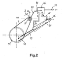
- FIG. 2 there is shown a schematic representation of the part of an alternative embodiment providing continuos rotational movement in the horizontal plane.
- This mechanism is thus to be regarded as an alternative to the stepwise mechanism for horizontal rotation of the column 3 provided by the gearmotor 4 and associated controlling means according to the first embodiment described above.
- the vertical column 3 of the cleaning device is provided with a chain wheel 31 connected for rotational movement to a second chain wheel 32 generally of a larger diameter by means of a chain 42.
- a chain wheel mechanism as shown in Figure 2 could also be replaced by various mechanical equivalent means such as a tooth belt, a rack and pinion mechanism, direct engagement between two gear wheels etc. without departing from the scope of the invention.
- the rotational movement of the larger diameter chain wheel 32 is attained by a pivotally mounted hydraulic cylinder 34, the piston rod 43 of which is connected to the larger diameter chain wheel 32 at a point 33.
- the mechanism is driven by the high-pressure fluid entering at the inlet 37 to a flow switch 36, which directs the flow of fluid either to one end of the hydraulic cylinder 34 via a first fluid outlet 38 or to the other end of the cylinder via the other outlet 39 of the flow switch 36.
- the flow switch 36 is controlled by an actuator arm 41, whenever this arm is actuated by an actuating member 40 on the vertical column 3.
- This mechanism is merely schematically indicated in Figure 2, but can easily be devised by a person skilled in the art.
- the vertical column 3 has been rotated in the direction of the arrow ⁇ to a point just prior to the activation of the flow switch.
- the piston rod 43 is displaced towards the cylinder 34, whereby the chain wheels 31 and 32 are rotated in the opposite direction.
- the column 3 is rotated once in the direction indicated by the arrow ⁇ , whereafter the direction of rotation is reversed and the column 3 rotates a full 360 degrees in the opposite direction and so on.
- the pivot arm 23 carrying the nozzle section 8 oscillates in the vertical plane as described in connection with the first embodiment and according to the second embodiment, the ray of washing fluid leaving the nozzle section 8 of the cleaning device thus describes a kind of sinusoidal pattern within a given vertical region surrounding the cleaning device.
Landscapes
- Engineering & Computer Science (AREA)
- Mechanical Engineering (AREA)
- Cleaning By Liquid Or Steam (AREA)
Abstract
A high-pressure cleaning device, for instance for cleaning of soiled enclosures such
as pigsties, is disclosed, the device comprising at least one nozzle section (8)
provided with drive means for movement hereof in two separate directions in space,
for instance horizontally and vertically, whereby a predetermined portion of the
surroundings of the device can be provided with high-pressure cleansing fluid. The
drive means for said movements are driven solely by the high-pressure fluid itself,
thereby providing a simple, yet safe and reliable device. According to one
embodiment of the device, a nozzle (8) is rotated in a stepwise manner in the
horizontal plane of the device, while the nozzle (8) simultaneously undergoes pivotal
movements in the vertical plane, thereby sweeping a certain, predetermined angular
range in the vertical plane.
Description
- The present invention relates to high-pressure cleaning devices for use in soiled surroundings or enclosures such as pigsties.
- Programmable devices or robots for carrying out cleansing operations for instance in large-scale agricultural plants or slaughterhouses are known within the art, which are able to move a nozzle section in a pre-programmed and complicated manner for instance throughout a row of enclosures, such as pigsties, and thereby performing complicated cleansing operations. In order to benefit optimally from such devices or robots, the surroundings in which they operate must, however, be designed accordingly, allowing for instance a robot to move automatically from one enclosure to the next. Unintended obstacles along the paths of movement of such robots are of course not allowed, and may even lead to hazardous situations. Furthermore, such devices may be unnecessarily complicated and hence expensive for use except in said large-scale plants, and they furthermore generally need to be supplied not only with the appropriate high-pressure fluid but also with electricity either via a direct connection to the AC mains supply or via built-in batteries.
- Hence, for many applications it would be desirable to have access to a simple and yet efficient and reliable cleaning device, which could be driven by the supply of high-pressure fluid itself.
- Based on the above background it is an object of the present invention to provide a high-pressure cleaning device for use in soiled enclosures, which is able to provide a desired coverage with a high-pressure cleaning fluid of a surface area totally surrounding the device in one plane, for instance the horizontal plane hereof, and with a coverage region - or angle - in another plane, for instance the vertical plane, which may be chosen according to the specific needs.
- According to the invention, the device is driven solely by means of the high-pressure fluid itself, i.e. the high-pressure fluid is used both for cleaning purposes and for attaining the necessary movements of parts of the device, such as a nozzle section, during the cleaning operation. Thus, with the device according to the invention only a suitable high-pressure fluid source is required and not for instance connections to the AC mains, thereby simplifying the use of the device and increasing its reliability and safety.
- The above objects and advantages are attained according to the invention by providing a cleaning device, in which at least one nozzle section for delivering high pressure cleaning fluid is provided with means for simultaneous movement in two dimensions in space, each of these means requiring only a supply of high pressure fluid to attain their movements and by which means cleaning fluid is provided to a region in space surrounding the cleaning device.
- According to a first class of specific embodiments of the invention, the cleaning fluid is provided to a region completely surrounding the device in the horizontal plane hereof, whereas the provision of cleaning fluid is restricted to a certain predetermined region in the vertical plane.
- According to a second class of specific embodiments of the invention, the cleaning fluid is provided to a region completely surrounding the device in the vertical plane hereof, whereas the provision of cleaning fluid is restricted to a certain predetermined region in the horizontal plane.
- According to the invention, the movement of the nozzle section in the horizontal and vertical planes can either take place continuously in both planes or alternatively continuously in one plane and in a stepwise manner in the other.
- A presently preferred embodiment of the invention comprising stepwise rotation of the nozzle section in the horizontal plane and simultaneous continuos pivotal movement within a predetermined vertical range is defined by claim 4. According to this embodiment of the invention, the nozzle is rotated about a vertical axis in steps, and for each of these steps a vertical sweep of the nozzle is performed between predetermined elevation angles, i.e. angles relative to the horizontal plane. The stepwise rotation about the vertical axis is continued over ― and as a possibility beyond ― a complete 360 degrees revolution in the horizontal plane with the effect that a complete cylindrical surface surrounding the device is being provided with cleansing fluid.
- A possible alternative would be to move the nozzle section stepwise in the vertical plane and rotate it continuously in the horizontal plane.
- By moving the nozzle section in the described combined stepwise and continuos manner, a full coverage of a predetermined area surrounding the device is ascertained, which would not have been the case if the nozzle section had been moved continuously and simultaneously in both dimensions in space. In the latter case the fluid leaving the nozzle would cover the surroundings in a kind of sinusoidal pattern, thus providing some parts of the surroundings with more cleansing fluid than other parts of the surroundings.
- Two alternative embodiments of the invention will now be described with reference to the accompanying drawing, where:
- Figure 1 shows a schematic representation of a preferred embodiment of the present invention embodying stepwise rotation in the horizontal plane and continuos pivotal movement in the vertical plane; and
- Figure 2 shows a schematic representation of the part of an alternative embodiment providing continuos rotational movement in the horizontal plane.
-
- Referring now to Figure 1, there is shown a schematic representation of an embodiment of the cleaning device according to the present invention. According to this embodiment the
nozzle 8 delivering the cleansing fluid is moved in an oscillating manner continuously over a certain, predefined angular range in the vertical plane, whereas the horizontal movement around the longitudinal axis X takes place in a stepwise manner over and beyond the entire 360 degrees azimuth interval. As mentioned above, other modes of movement of thenozzle 8 would also fall within the general inventive concept, as defined by theindependent claim 1. - As shown in Figure 1, the
nozzle 8 is supported for oscillatory movement in the vertical plane, as indicated by the arrow B, on apivot arm 23 via apivot joint 24. By means of thisjoint 24, the vertical angle of thenozzle 8 relative to thepivot arm 23 can be adjusted, thereby determining the limits of the vertical coverage angle of the nozzle in accordance with the specific requirements during use of the device. Thepivot arm 23 is pivotally connected to a supportingarm 22 attached to thevertical column 3, such that thearm 23 can rotate in the horizontal direction. - The stepwise horizontal rotation is achieved by the application of a hydraulic gearmotor 4 carrying the
column 3 and mounted on astand 2 which may be provided with (not shown) wheels or rollers to facilitate transport of the device. High-pressure fluid is entered via the inlet 9 for driving the gearmotor 4, whereupon the fluid leaves the gearmotor 4 at anoutlet 10 hereof and passes through thecolumn 3 via a pipeline 11. - The gearmotor 4 is provided with an actuator device 5 comprising an actuator arm 6. When the free end of the actuator arm 6 is in its lowermost position, the gearmotor 4 is able to undergo a rotation by one azimuthal step in the direction of the arrow A, whereupon it remains in this position until the actuator arm 6 again resumes its lowermost position. The gearmotor then rotates another azimuthal step and so on.
- After leaving the
column 3 at the upper end hereof, the pipeline 11 is terminated by a T-connection in which the flow of high-pressure fluid is split up into a portion delivered to thenozzle 8 via a suitable flexible connection, such as thehose 12 and a portion leaving the T-connection through thepipeline 13. This portion of the fluid is used to drive the vertical and horizontal movements of the device, as described below. - After passage of a
valve 25 in thepipeline 13, this portion of the fluid enters a flow switch 14 provided with two outlets a and b. The switch 14 is provided with anarm 15 for directing the fluid to either one or the outer of the outlets a and b. The outlet a is connected via apipeline 18 to anupper inlet 29 of ahydraulic cylinder 21, whereas the outlet b is connected via apipeline 17 to alower inlet 30 of thehydraulic cylinder 21. When thecylinder 21 receives fluid under pressure at theupper inlet 29, the piston of the cylinder is driven in a downward direction and when pressurised fluid is received via thelower inlet 30, the piston is driven in an upwards direction in thecylinder 21. Thecylinder 21 is pivotally attached to thecolumn 3 and the distal end of the piston rod 27 from the piston in the cylinder is pivotally connected to thepivot arm 23. Thus, a reciprocating movement of the piston of thehydraulic cylinder 21 is transformed to an oscillating movement of thearm 23 carrying thenozzle 8. - A connecting
arm 19 passes between a point on thepivot arm 23 carrying thenozzle 8 and the actuator arm 6 of the gear motor 4. Thus, the actuator arm 6 follows the oscillatory motion of thepivot arm 23, and whenever thepivot arm 23 is in its lowermost position, the gearmotor thus rotates one step in the direction of the arrow A. - The flow switch 14 switches between its two states, thereby directing the flow of fluid to either the outlet a or the outlet b, controlled by the movement of the connecting
arm 19. To accomplish this, the flowswitch actuator arm 15 is connected to a connecting member 20 on the connectingarm 19 by means of atension member 16, for instance a helical spring. In this manner the switch acts as a bistable switch, which practically momentarily switches between its two states at the appropriate position of the connectingarm 19. - The rate of flow of fluid through the
pipeline 13 is controlled by means of thevalve 25 provided with a suitable adjustment means 26. By this adjustment, the speed of the oscillatory movement of thenozzle 8 and hence the rotational speed of the device around the longitudinal axis X through thevertical column 3 can be varied according to the specific needs. - Referring now to Figure 2, there is shown a schematic representation of the part of an alternative embodiment providing continuos rotational movement in the horizontal plane. This mechanism is thus to be regarded as an alternative to the stepwise mechanism for horizontal rotation of the
column 3 provided by the gearmotor 4 and associated controlling means according to the first embodiment described above. - According to this embodiment, the
vertical column 3 of the cleaning device is provided with achain wheel 31 connected for rotational movement to asecond chain wheel 32 generally of a larger diameter by means of achain 42. It is, however, understood that in principle the chain wheel mechanism as shown in Figure 2 could also be replaced by various mechanical equivalent means such as a tooth belt, a rack and pinion mechanism, direct engagement between two gear wheels etc. without departing from the scope of the invention. The rotational movement of the largerdiameter chain wheel 32 is attained by a pivotally mountedhydraulic cylinder 34, thepiston rod 43 of which is connected to the largerdiameter chain wheel 32 at apoint 33. By proper choice of the diameters of thechain wheels vertical column 3 for a limited rotation of thelarger chain wheel 32, as indicated by the angle δ in Figure 2. The mechanism is driven by the high-pressure fluid entering at theinlet 37 to aflow switch 36, which directs the flow of fluid either to one end of thehydraulic cylinder 34 via afirst fluid outlet 38 or to the other end of the cylinder via theother outlet 39 of theflow switch 36. Theflow switch 36 is controlled by anactuator arm 41, whenever this arm is actuated by an actuatingmember 40 on thevertical column 3. This mechanism is merely schematically indicated in Figure 2, but can easily be devised by a person skilled in the art. As shown in Figure 2, thevertical column 3 has been rotated in the direction of the arrow α to a point just prior to the activation of the flow switch. When the flow of fluid is brought to enter thecylinder 34 via theoutlet 39, thepiston rod 43 is displaced towards thecylinder 34, whereby thechain wheels chain wheels column 3 is rotated once in the direction indicated by the arrow δ, whereafter the direction of rotation is reversed and thecolumn 3 rotates a full 360 degrees in the opposite direction and so on. - Simultaneously with the above described continuos horizontal rotation, the
pivot arm 23 carrying thenozzle section 8 oscillates in the vertical plane as described in connection with the first embodiment and according to the second embodiment, the ray of washing fluid leaving thenozzle section 8 of the cleaning device thus describes a kind of sinusoidal pattern within a given vertical region surrounding the cleaning device. -
- 1.
- Cleaning device according to first embodiment
- 2.
- Stand
- 3.
- Vertical column
- 4.
- Hydraulic gearmotor
- 5.
- Actuator for gearmotor
- 6.
- Actuator arm
- 7.
- T-connector
- 8.
- Nozzle
- 9.
- Inlet for high-pressure fluid
- 10.
- Outlet from gear motor
- 11.
- Pipeline through vertical column
- 12.
- Hose
- 13.
- Pipeline
- 14.
- Flow switch
- 15.
- Flow switch actuator arm
- 16.
- Tension member
- 17.
- Pipeline
- 18.
- Pipeline
- 19.
- Connecting arm
- 20.
- Connecting member
- 21.
- Hydraulic cylinder
- 22.
- Supporting arm
- 23.
- Pivot arm for nozzle
- 24.
- Pivot joint for nozzle
- 25.
- Valve
- 26.
- Adjustment means for valve
- 27.
- Piston rod of hydraulic cylinder
- 28.
- Pivot joint for piston arm
- 29.
- Upper inlet of cylinder
- 30.
- Lower inlet of cylinder
- 31.
- Small diameter chain wheel
- 32.
- Large diameter chain wheel
- 33.
- Connection of piston rod to large diameter chain wheel
- 34.
- Hydraulic cylinder
- 35.
- Pivot point of
hydraulic cylinder 34 - 36.
- Flow switch
- 37.
- Fluid inlet
- 38.
- First fluid outlet
- 39.
- Second fluid outlet
- 40.
- Flow switch actuating member on
rotatable column 3 - 41.
- Actuator arm of flow switch
- 42.
- Chain
- 43.
- Piston rod of hydraulic cylinder
- A.
- Horizontal rotation
- B.
- Vertical oscillation
- X.
- Longitudinal axis through vertical column.
Claims (21)
- High-pressure cleaning device for cleaning pigsties and other contaminated enclosures comprising at least one nozzle section (8) for the provision of a high-pressure cleansing fluid and means for changing the orientation of the at least one nozzle section (8) in two different spatial dimensions, characterised in that said means for changing the orientation are driven solely by the high-pressure cleansing fluid itself.
- High-pressure cleaning device according to claim 1, characterised in that said device is provided with means for changing the orientation of said at least one nozzle section (8) in a first of said dimensions continuously and with means for changing the orientation of said at least one nozzle section (8) in the second of said dimensions in a stepwise manner.
- High-pressure cleaning device according to claim 1, characterised in that said device is provided with means for changing the orientation of said at least one nozzle section (8) in a first of said dimensions continuously and with means for changing the orientation of said at least one nozzle section (8) in the second of said dimensions in a continuos manner.
- High-pressure cleaning device according to claim 2, characterised in that said at least one nozzle section (8) is mounted and driven for pivotal movement, thereby sweeping over a given range in the vertical plane, and where the at least one nozzle section (8) is furthermore mounted and driven for stepwise rotational movement in the horizontal plane about a vertical axis (X), where the drive means (21) for said pivotal movement is coupled to the drive means (4) for said stepwise rotation in such a manner that the at least one nozzle section (8) moves one step further in the horizontal plane at the completion of each of said pivotal movements in the vertical plane.
- High-pressure cleaning device according to claim 4, characterised in that said drive means for the pivotal movement is a hydraulic cylinder (21), the piston of which is connected (27) to a pivot arm (23) carrying the at least one nozzle section (8).
- High-pressure cleaning device according to claim 4 or 5, characterised in that said drive means (4) for the stepwise rotation is a controllable gearmotor (4) attached to a structure (3, 22) carrying said pivot arm (23).
- High-pressure cleaning device according to claim 6, characterised in that said gearmotor (4) is provided with actuator means (5, 6) for controlling the gearmotor (4), said actuator means (5, 6) being connected (19) to and activated by said pivot arm (23).
- High-pressure cleaning device according to any of the preceding claims 4 to 7, characterised in that said hydraulic cylinder (21 ) is provided with an upper (29) and a lower (30) inlet for high-pressure fluid, whereby the piston in the hydraulic cylinder (21) is moved in one direction when fluid is applied via said upper inlet (29) and in the opposite direction when fluid is applied via said lower inlet (30), said inlets (29, 30) being provided with fluid via a flow switch (14) receiving high-pressure fluid from a high-pressure fluid source.
- High-pressure cleaning device according to claim 8, characterised in that the supply of fluid to said flow switch (14) can be adjusted by means of a valve (25), whereby the rate of movement of the at least one nozzle section (8) can be adjusted.
- High-pressure cleaning device according to claim 8 or 9, characterised in that said flow switch (14) via activating means (15) is connected (20) for switching to said connecting arm (19) by means of a tension member (16).
- High-pressure cleaning device according to claim 3, characterised in that said at least one nozzle section (8) is mounted and driven for pivotal movement, thereby sweeping over a given range in the vertical plane, and where the at least one nozzle section (8) is furthermore mounted and driven for continuos rotational movement in the horizontal plane about a vertical axis (X), where the drive means for said continuos rotational movement in the horizontal plane comprises a wheel (31) mounted on the vertical column (3) and coupled to a second wheel (32) driven for rotation over a given, predetermined angle (δ).
- High-pressure cleaning device according to claim 11, characterised in that said second wheel (32) is driven by a hydraulic cylinder (34).
- High-pressure cleaning device according to claim 11 or 12, characterised in that said first and second wheels (31, 32) are chain wheels and said coupling between these wheels is a chain (42).
- High-pressure cleaning device according to any of the preceding claims 11 to 13, characterised in that said hydraulic cylinder (34) is driven for reciprocating movement of the piston and rod (43) by the high-pressure fluid being supplied alternately at either end of the cylinder (34) via a flow switch (36).
- High pressure cleaning device according to claim 14, characterised in that said flow switch (36) is activated by the rotational movement of the vertical column (3) by activation means (40, 41) attached to the vertical column (3) and to the flow switch (36), respectively.
- High-pressure cleaning device according to any of the preceding claims 11 to 15, characterised in that the diameters of said first and second wheel (31, 32) are chosen such that said rotation of the second wheel (32) causes a predetermined rotation angle (α) of the vertical column (3).
- High-pressure cleaning device according to claim 16, characterised in that said rotation angle (α) is substantially 360 degrees.
- High-pressure cleaning device according to any of the preceding claims characterised in that said two dimensions are substantially orthogonal.
- High-pressure cleaning device according to any of the preceding claims, characterised in that said first dimension is substantially vertical and said second dimension is substantially horizontal.
- High-pressure cleaning device according to any of the preceding claims, characterised in that said first dimension is substantially horizontal and said second dimension is substantially vertical.
- High-pressure cleaning device according to any of the preceding claims, characterised in that said nozzle (8) is connected to said pivot arm (23) by a pivot joint (24), whereby the orientation of the nozzle (8) relative to pivot arm (13) is made adjustable.
Priority Applications (1)
| Application Number | Priority Date | Filing Date | Title |
|---|---|---|---|
| EP03000865A EP1439003A1 (en) | 2003-01-15 | 2003-01-15 | High-pressure cleaning device |
Applications Claiming Priority (1)
| Application Number | Priority Date | Filing Date | Title |
|---|---|---|---|
| EP03000865A EP1439003A1 (en) | 2003-01-15 | 2003-01-15 | High-pressure cleaning device |
Publications (1)
| Publication Number | Publication Date |
|---|---|
| EP1439003A1 true EP1439003A1 (en) | 2004-07-21 |
Family
ID=32524136
Family Applications (1)
| Application Number | Title | Priority Date | Filing Date |
|---|---|---|---|
| EP03000865A Withdrawn EP1439003A1 (en) | 2003-01-15 | 2003-01-15 | High-pressure cleaning device |
Country Status (1)
| Country | Link |
|---|---|
| EP (1) | EP1439003A1 (en) |
Cited By (4)
| Publication number | Priority date | Publication date | Assignee | Title |
|---|---|---|---|---|
| JP2015223392A (en) * | 2014-05-29 | 2015-12-14 | 酒井医療株式会社 | Automatic hair washing device and bathing device |
| EP3124127A1 (en) * | 2015-07-29 | 2017-02-01 | Buchen Umweltservice GmbH | High-pressure cleaning device for cleaning small parts |
| CN108005195A (en) * | 2017-12-29 | 2018-05-08 | 江苏风潮科技有限公司 | Intelligent toilet cover spray boom swings water spraying mechanism |
| CN117139262A (en) * | 2023-10-31 | 2023-12-01 | 沈阳华钛实业有限公司 | High-pressure water cleaning equipment based on angle adjustment |
Citations (4)
| Publication number | Priority date | Publication date | Assignee | Title |
|---|---|---|---|---|
| US2029788A (en) * | 1935-02-08 | 1936-02-04 | Pyrate Corp | Tank washing apparatus |
| US2322271A (en) * | 1940-09-23 | 1943-06-22 | William N Bagley | Irrigation sprinkler |
| US2635007A (en) * | 1951-03-23 | 1953-04-14 | Eric A Norman | Oscillating hydraulic nozzle assembly |
| US5462227A (en) * | 1994-08-18 | 1995-10-31 | Ping; Wu K. | Automatic cleaning device for use on a stock farm |
-
2003
- 2003-01-15 EP EP03000865A patent/EP1439003A1/en not_active Withdrawn
Patent Citations (4)
| Publication number | Priority date | Publication date | Assignee | Title |
|---|---|---|---|---|
| US2029788A (en) * | 1935-02-08 | 1936-02-04 | Pyrate Corp | Tank washing apparatus |
| US2322271A (en) * | 1940-09-23 | 1943-06-22 | William N Bagley | Irrigation sprinkler |
| US2635007A (en) * | 1951-03-23 | 1953-04-14 | Eric A Norman | Oscillating hydraulic nozzle assembly |
| US5462227A (en) * | 1994-08-18 | 1995-10-31 | Ping; Wu K. | Automatic cleaning device for use on a stock farm |
Cited By (6)
| Publication number | Priority date | Publication date | Assignee | Title |
|---|---|---|---|---|
| JP2015223392A (en) * | 2014-05-29 | 2015-12-14 | 酒井医療株式会社 | Automatic hair washing device and bathing device |
| EP3124127A1 (en) * | 2015-07-29 | 2017-02-01 | Buchen Umweltservice GmbH | High-pressure cleaning device for cleaning small parts |
| CN108005195A (en) * | 2017-12-29 | 2018-05-08 | 江苏风潮科技有限公司 | Intelligent toilet cover spray boom swings water spraying mechanism |
| CN108005195B (en) * | 2017-12-29 | 2023-08-01 | 江苏风潮科技有限公司 | Intelligent toilet lid spray rod swing water spraying mechanism |
| CN117139262A (en) * | 2023-10-31 | 2023-12-01 | 沈阳华钛实业有限公司 | High-pressure water cleaning equipment based on angle adjustment |
| CN117139262B (en) * | 2023-10-31 | 2023-12-26 | 沈阳华钛实业有限公司 | High-pressure water cleaning equipment based on angle adjustment |
Similar Documents
| Publication | Publication Date | Title |
|---|---|---|
| KR101068421B1 (en) | Devices for internal cleaning of tanks or containers | |
| US8127390B2 (en) | Robot for cleaning wall/window | |
| US11300981B2 (en) | Rotary tool with smart indexer | |
| US8122898B2 (en) | High-pressure apparatus and method for removing scale from a tank | |
| US20170343308A1 (en) | Cleaning system and method | |
| US11294399B2 (en) | Rotary tool with smart indexing | |
| CN111014131A (en) | Automatic cleaning robot | |
| US9162652B2 (en) | Car wash spray arch | |
| CN113499903A (en) | Five-degree-of-freedom disinfection mechanical arm based on double-nozzle electric spray gun | |
| US4585387A (en) | Robot arm | |
| KR100386898B1 (en) | Cleaning device | |
| CN110237623A (en) | A kind of construction environmental protection device for reducing dust | |
| CN116832559B (en) | Construction dust fall equipment | |
| CN110810219A (en) | A movable swing type sprinkler irrigation equipment | |
| CN108556808A (en) | A kind of washing and disinfection car | |
| CN104646210A (en) | Spraying machine with function of automatic control over swing and steering | |
| CN108554891A (en) | A kind of control arm of washing and disinfection car | |
| CN107962054A (en) | Interchangeable plate operation cleaning robot applied to photovoltaic array changes plate method | |
| CN209772442U (en) | Planetary rotary spray washing equipment | |
| US20100154843A1 (en) | Liquid applicator for cleaning a vehicle | |
| CN109078937A (en) | A kind of pipeline cleaning robot | |
| EP4615642B1 (en) | Container cleaner | |
| CN108246552A (en) | A kind of multi-faceted watering spray executive device of driven type | |
| CN220678869U (en) | Automatic cleaning device for reaction kettle tank body in chemical and pharmaceutical industry | |
| CN220144238U (en) | Pipeline cleaning device |
Legal Events
| Date | Code | Title | Description |
|---|---|---|---|
| PUAI | Public reference made under article 153(3) epc to a published international application that has entered the european phase |
Free format text: ORIGINAL CODE: 0009012 |
|
| AK | Designated contracting states |
Kind code of ref document: A1 Designated state(s): AT BE BG CH CY CZ DE DK EE ES FI FR GB GR HU IE IT LI LU MC NL PT SE SI SK TR |
|
| AX | Request for extension of the european patent |
Extension state: AL LT LV MK RO |
|
| STAA | Information on the status of an ep patent application or granted ep patent |
Free format text: STATUS: THE APPLICATION HAS BEEN WITHDRAWN |
|
| 18W | Application withdrawn |
Effective date: 20041126 |