CN111014131A - Automatic cleaning robot - Google Patents
Automatic cleaning robot Download PDFInfo
- Publication number
- CN111014131A CN111014131A CN201911101743.7A CN201911101743A CN111014131A CN 111014131 A CN111014131 A CN 111014131A CN 201911101743 A CN201911101743 A CN 201911101743A CN 111014131 A CN111014131 A CN 111014131A
- Authority
- CN
- China
- Prior art keywords
- pipe
- outlet
- assembly
- pressure water
- frame
- Prior art date
- Legal status (The legal status is an assumption and is not a legal conclusion. Google has not performed a legal analysis and makes no representation as to the accuracy of the status listed.)
- Pending
Links
- 238000004140 cleaning Methods 0.000 title claims abstract description 58
- XLYOFNOQVPJJNP-UHFFFAOYSA-N water Substances O XLYOFNOQVPJJNP-UHFFFAOYSA-N 0.000 claims abstract description 180
- 239000007921 spray Substances 0.000 claims abstract description 52
- 239000003814 drug Substances 0.000 claims abstract description 34
- 238000004804 winding Methods 0.000 claims abstract description 25
- 239000006260 foam Substances 0.000 claims abstract description 23
- 229910000831 Steel Inorganic materials 0.000 claims abstract description 14
- 239000010959 steel Substances 0.000 claims abstract description 14
- 239000007788 liquid Substances 0.000 claims description 66
- 230000009977 dual effect Effects 0.000 claims description 16
- 238000005507 spraying Methods 0.000 claims description 8
- 238000005406 washing Methods 0.000 claims description 5
- 238000004891 communication Methods 0.000 claims description 3
- 230000000903 blocking effect Effects 0.000 claims description 2
- 230000000149 penetrating effect Effects 0.000 claims description 2
- 229940079593 drug Drugs 0.000 abstract description 3
- 230000005540 biological transmission Effects 0.000 description 25
- 238000010586 diagram Methods 0.000 description 9
- WHXSMMKQMYFTQS-UHFFFAOYSA-N Lithium Chemical compound [Li] WHXSMMKQMYFTQS-UHFFFAOYSA-N 0.000 description 7
- 229910052744 lithium Inorganic materials 0.000 description 7
- 239000003638 chemical reducing agent Substances 0.000 description 6
- 239000000126 substance Substances 0.000 description 6
- 244000144972 livestock Species 0.000 description 4
- 230000001360 synchronised effect Effects 0.000 description 4
- 230000009471 action Effects 0.000 description 3
- 230000000712 assembly Effects 0.000 description 3
- 238000000429 assembly Methods 0.000 description 3
- 238000009395 breeding Methods 0.000 description 3
- 230000001488 breeding effect Effects 0.000 description 3
- 230000036541 health Effects 0.000 description 3
- 241000201246 Cycloloma atriplicifolium Species 0.000 description 2
- 230000008878 coupling Effects 0.000 description 2
- 238000010168 coupling process Methods 0.000 description 2
- 238000005859 coupling reaction Methods 0.000 description 2
- 239000000645 desinfectant Substances 0.000 description 2
- 230000000249 desinfective effect Effects 0.000 description 2
- 230000005484 gravity Effects 0.000 description 2
- 230000003993 interaction Effects 0.000 description 2
- 230000005389 magnetism Effects 0.000 description 2
- 238000000034 method Methods 0.000 description 2
- 239000000203 mixture Substances 0.000 description 2
- 238000004659 sterilization and disinfection Methods 0.000 description 2
- 241000196324 Embryophyta Species 0.000 description 1
- 206010063385 Intellectualisation Diseases 0.000 description 1
- 230000009286 beneficial effect Effects 0.000 description 1
- 238000006243 chemical reaction Methods 0.000 description 1
- 230000003670 easy-to-clean Effects 0.000 description 1
- 230000000694 effects Effects 0.000 description 1
- 238000011086 high cleaning Methods 0.000 description 1
- 230000006872 improvement Effects 0.000 description 1
- 230000004048 modification Effects 0.000 description 1
- 238000012986 modification Methods 0.000 description 1
- 230000008569 process Effects 0.000 description 1
- 230000000452 restraining effect Effects 0.000 description 1
- 238000006467 substitution reaction Methods 0.000 description 1
Images


Classifications
-
- B—PERFORMING OPERATIONS; TRANSPORTING
- B08—CLEANING
- B08B—CLEANING IN GENERAL; PREVENTION OF FOULING IN GENERAL
- B08B3/00—Cleaning by methods involving the use or presence of liquid or steam
- B08B3/02—Cleaning by the force of jets or sprays
-
- A—HUMAN NECESSITIES
- A01—AGRICULTURE; FORESTRY; ANIMAL HUSBANDRY; HUNTING; TRAPPING; FISHING
- A01K—ANIMAL HUSBANDRY; AVICULTURE; APICULTURE; PISCICULTURE; FISHING; REARING OR BREEDING ANIMALS, NOT OTHERWISE PROVIDED FOR; NEW BREEDS OF ANIMALS
- A01K1/00—Housing animals; Equipment therefor
- A01K1/01—Removal of dung or urine, e.g. from stables
-
- A—HUMAN NECESSITIES
- A01—AGRICULTURE; FORESTRY; ANIMAL HUSBANDRY; HUNTING; TRAPPING; FISHING
- A01K—ANIMAL HUSBANDRY; AVICULTURE; APICULTURE; PISCICULTURE; FISHING; REARING OR BREEDING ANIMALS, NOT OTHERWISE PROVIDED FOR; NEW BREEDS OF ANIMALS
- A01K31/00—Housing birds
- A01K31/04—Dropping-boards; Devices for removing excrement
-
- A—HUMAN NECESSITIES
- A61—MEDICAL OR VETERINARY SCIENCE; HYGIENE
- A61L—METHODS OR APPARATUS FOR STERILISING MATERIALS OR OBJECTS IN GENERAL; DISINFECTION, STERILISATION OR DEODORISATION OF AIR; CHEMICAL ASPECTS OF BANDAGES, DRESSINGS, ABSORBENT PADS OR SURGICAL ARTICLES; MATERIALS FOR BANDAGES, DRESSINGS, ABSORBENT PADS OR SURGICAL ARTICLES
- A61L2/00—Methods or apparatus for disinfecting or sterilising materials or objects other than foodstuffs or contact lenses; Accessories therefor
- A61L2/16—Methods or apparatus for disinfecting or sterilising materials or objects other than foodstuffs or contact lenses; Accessories therefor using chemical substances
- A61L2/18—Liquid substances or solutions comprising solids or dissolved gases
-
- A—HUMAN NECESSITIES
- A61—MEDICAL OR VETERINARY SCIENCE; HYGIENE
- A61L—METHODS OR APPARATUS FOR STERILISING MATERIALS OR OBJECTS IN GENERAL; DISINFECTION, STERILISATION OR DEODORISATION OF AIR; CHEMICAL ASPECTS OF BANDAGES, DRESSINGS, ABSORBENT PADS OR SURGICAL ARTICLES; MATERIALS FOR BANDAGES, DRESSINGS, ABSORBENT PADS OR SURGICAL ARTICLES
- A61L2202/00—Aspects relating to methods or apparatus for disinfecting or sterilising materials or objects
- A61L2202/10—Apparatus features
- A61L2202/17—Combination with washing or cleaning means
-
- B—PERFORMING OPERATIONS; TRANSPORTING
- B08—CLEANING
- B08B—CLEANING IN GENERAL; PREVENTION OF FOULING IN GENERAL
- B08B2203/00—Details of cleaning machines or methods involving the use or presence of liquid or steam
- B08B2203/02—Details of machines or methods for cleaning by the force of jets or sprays
- B08B2203/0217—Use of a detergent in high pressure cleaners; arrangements for supplying the same
-
- B—PERFORMING OPERATIONS; TRANSPORTING
- B08—CLEANING
- B08B—CLEANING IN GENERAL; PREVENTION OF FOULING IN GENERAL
- B08B2203/00—Details of cleaning machines or methods involving the use or presence of liquid or steam
- B08B2203/02—Details of machines or methods for cleaning by the force of jets or sprays
- B08B2203/0258—Multiple lance high pressure cleaning station
-
- B—PERFORMING OPERATIONS; TRANSPORTING
- B08—CLEANING
- B08B—CLEANING IN GENERAL; PREVENTION OF FOULING IN GENERAL
- B08B2203/00—Details of cleaning machines or methods involving the use or presence of liquid or steam
- B08B2203/02—Details of machines or methods for cleaning by the force of jets or sprays
- B08B2203/0276—Hose reels specific for high pressure cleaners
Landscapes
- Life Sciences & Earth Sciences (AREA)
- Environmental Sciences (AREA)
- Zoology (AREA)
- Biodiversity & Conservation Biology (AREA)
- Health & Medical Sciences (AREA)
- Animal Husbandry (AREA)
- Epidemiology (AREA)
- General Health & Medical Sciences (AREA)
- Public Health (AREA)
- Veterinary Medicine (AREA)
- Birds (AREA)
- Animal Behavior & Ethology (AREA)
- Chemical & Material Sciences (AREA)
- General Chemical & Material Sciences (AREA)
- Chemical Kinetics & Catalysis (AREA)
- Cleaning By Liquid Or Steam (AREA)
Abstract
The invention discloses an automatic cleaning robot, comprising: a running part driven by the first driving assembly; the pipe coiling wheel disc is arranged on the first frame and comprises disc bodies on two sides, a water passing rotating shaft and a plurality of winding rollers, and the water passing rotating shaft is driven to rotate by the second driving assembly; the screw rod assembly comprises a screw rod and a guide device, and the screw rod and the pipe coiling wheel disc rotate in a linkage manner; at least one drug solution tank; a siphon valve having at least one inlet and outlet; the water spray assembly comprises a swing driving assembly and a switchable double-nozzle, the switchable double-nozzle is driven by the swing driving assembly and can swing, the switchable double-nozzle comprises a steel ball, an inlet, a first outlet, a second outlet, a high-pressure water spray head and a foam spray head, and the steel ball blocks a flow path between the inlet and the first outlet or a flow path between the inlet and the second outlet; and the supporting arm is arranged on the second frame and is connected with at least one water spray assembly. The intelligent automatic cleaning system is used for intelligently and efficiently realizing automatic cleaning operation.
Description
Technical Field
The invention belongs to the technical field of automatic cleaning, and particularly relates to an automatic cleaning robot.
Background
Along with the improvement of living standard of people, the livestock breeding industry is more and more prosperous, and along with the technological progress, the large-scale intensive farm is also more and more, and the biosafety risk that brings from this is also higher and more, consequently, the cleaning and disinfecting demand of the livestock breeding industry is also increasing day by day.
Traditional cleaning operation, need artifical handheld high pressure water pipe to soak and wash the washing region, the manual work sprays foam cleaner and its surface region foul reaction and softening afterwards, and reuse high pressure water pipe washes it repeatedly, wash and accomplish back rethread hand-held sterilizer and spray the disinfection repeatedly to livestock breeding space, this cleaning process intensity of labour is big, the cleaning efficiency is low, also there is the problem at clearance dead angle, and plant's environment is complicated various, need the product and the cleaning method of different specifications to different scenes sometimes, undoubtedly these can bring the difficulty in the operation for the purger, and then greatly reduced cleaning efficiency, furthermore, abominable washing and disinfecting operational environment produces the hidden danger to operating personnel's safety and health.
Therefore, for large-scale farms, an automatic cleaning operation mode capable of replacing manual operation is urgently needed to intelligently and efficiently realize automatic cleaning operation and meet different scenes and different cleaning modes.
Disclosure of Invention
The invention aims to provide an automatic cleaning robot, which is used for solving the problems of high labor intensity, low cleaning efficiency and poor applicability caused by traditional manual cleaning and intelligently and efficiently realizing automatic cleaning operation.
In order to solve the technical problems, the invention provides the following technical scheme for solving the problems:
an automatic cleaning robot, comprising: a first drive assembly; a running gear driven by the first drive assembly; a second drive assembly; a first frame carried by the running gear; the pipe coiling wheel disc is arranged on the first frame and comprises disc bodies on two sides, a water through rotating shaft connected with the two disc bodies and a plurality of winding rollers for winding a high-pressure water pipe, and the water through rotating shaft is driven by the second driving assembly to rotate and is communicated with a water outlet of the high-pressure water pipe; the guide device is used for guiding the high-pressure water pipe when the high-pressure water pipe is retracted and released; at least one liquid medicine box, wherein the liquid medicine in each liquid medicine box is different in type; the siphon valve is provided with at least one liquid inlet and one liquid outlet, and each liquid inlet is respectively communicated with the water-through rotating shaft and each liquid medicine box; a water spray assembly including a swing driving assembly and a switchable dual spray head driven by the swing driving assembly and swingable, the switchable dual spray head including a switcher, a high pressure water spray head, and a foam spray head, the switcher including a steel ball, an inlet, a first outlet, and a second outlet, the inlet communicating with a liquid outlet of the siphon valve, the high pressure water spray head being inserted at the first outlet, the foam spray head being inserted at the second outlet, the steel ball selectively blocking a flow path between the inlet and the first outlet or a flow path between the inlet and the second outlet; a second frame carried by the running gear; the supporting arm is arranged on the second frame, and at least one water spray assembly is connected to the supporting arm; the electric cabinet is used for controlling the automatic cleaning robot to act; and the power supply supplies power to all electric appliances in the automatic cleaning robot.
The automatic cleaning robot further comprises a third driving assembly and a rotating connecting piece, wherein the rotating connecting piece is sleeved on the supporting arm, and the third driving assembly drives the rotating connecting piece to rotate together with the supporting arm.
The robot cleaner as described above, the support arm including a left support arm portion and a right support arm portion; the rotary connecting piece comprises a left rotary connecting piece and a right rotary connecting piece; the left rotating connecting piece is sleeved on the left supporting arm part, and one end of the left supporting arm part is connected with the water spraying assembly; the right rotating connecting piece is sleeved on the right supporting arm part, and one end of the right supporting arm part is connected with the water spraying assembly; the third drive assembly drives the left and right pivotal connections to pivot in conjunction with the left and right support arm portions.
The automatic cleaning robot as described above further includes: a pipe shaft, one end of which is inserted into the left rotating connecting piece and the other end of which is inserted into the right rotating connecting piece, and the other end of the left supporting arm part and the other end of the right supporting arm part are both positioned in the pipe shaft, and the pipe shaft rotates together with the left rotating connecting piece and the right rotating connecting piece; a first rack is formed on one side surface of the other end of the left support arm portion, and a second rack opposite to the first rack is formed on one side surface of the other end of the right support arm portion; a gear assembly fixed on the pipe shaft, wherein gears in the gear assembly are meshed with the first rack and the second rack; and an output shaft of the telescopic motor is connected with the gear of the gear assembly.
The robot cleaner as described above, wherein the swing driving unit includes: a swing motor; a worm connected to an output shaft of the swing motor; a worm gear engaged with the worm; and the swinging pipe shaft is arranged in the center of the worm wheel in a penetrating manner, one end of the swinging pipe shaft is communicated with the inlet of the switcher, and the other end of the swinging pipe shaft is communicated with the liquid outlet of the siphon valve.
According to the automatic cleaning robot, the swing motor is connected with the worm through the flexible shaft.
The automatic cleaning robot further comprises a lifting driving component which drives the second frame to lift.
The robot cleaner as described above, wherein the guide means includes: a guide frame; the thread block is arranged at the bottom of the guide frame and is provided with a thread through hole, and the lead screw is in threaded connection with the thread hole; an auxiliary reel pipe drive assembly; the first driving roller is driven by the auxiliary roller pipe driving assembly to rotate, and the first driving roller is parallel to the lead screw and penetrates through the guide frame; the first guide wheel is positioned in the guide frame and sleeved on the first driving roller, and the first guide wheel rotates along with the rotation of the first driving roller; and the second guide wheel is rotatably arranged in the guide frame and is parallel to the first guide wheel, and the high-pressure water pipe penetrates through a gap between the first guide wheel and the second guide wheel.
The automatic cleaning robot further comprises a guide roller arranged on the first frame and parallel to the first driving roller, an arc-shaped groove is formed in the top of the guide frame, and part of the outer side surface of the guide roller is embedded into the arc-shaped groove.
The automatic cleaning robot further comprises a remote control device communicated with the wireless receiving module in the electric cabinet, and the remote control device remotely transmits a remote control signal for enabling the automatic cleaning robot to act.
Compared with the prior art, the invention has the advantages and beneficial effects that: the electric cabinet automatically controls the cleaning robot to act, and controls the first driving assembly to drive the walking part to walk, so that the robot automatically controls walking; when the high-pressure water pipe needs to be wound and unwound, the electric cabinet sends a signal to the second driving assembly, the second driving assembly drives the water passing rotating shaft and the lead screw to rotate in a linkage manner, and then the whole reel pipe wheel disc is driven to rotate, and the water outlet of the high-pressure water pipe is communicated with the water passing rotating shaft, namely the water passing rotating shaft is connected with one end of the high-pressure water pipe, so that the high-pressure water pipe is in a winding and unwinding state while the water passing rotating shaft drives the reel pipe wheel disc to rotate, and the high-pressure water pipe is wound on the winding roller or discharged from the winding roller along with the movement of the guide device on the lead screw, so that; the high-pressure water or the mixed liquid of the high-pressure water and each liquid medicine can be output from the liquid outlet of the siphon valve through controlling the siphon valve, so that the high-pressure water or the mixed liquid can be correspondingly sprayed when different spray heads are switched through the switcher, and the automatic switching of the high-pressure water or the mixed liquid is realized; the support arm is arranged on the second frame and is provided with a water spraying assembly, switchable double spray heads in the water spraying assembly can be driven to swing by swinging, and the switchable double spray heads can swing on a plane vertical to the support arm, so that the spray heads are suitable for various scenes, and the application range of the robot is expanded; the robot is high in automation degree, high in cleaning efficiency and high in user experience, reduces the manual task amount, and avoids harm of severe cleaning environment to health.
Other features and advantages of the present invention will become more apparent from the following detailed description of the invention when taken in conjunction with the accompanying drawings.
In order to more clearly illustrate the technical solutions in the embodiments of the present invention, the drawings needed to be used in the embodiments are briefly introduced below, and it is obvious that the drawings in the following description are some embodiments of the present invention, and it is obvious for those skilled in the art to obtain other drawings based on these drawings without creative efforts.
Fig. 1 is an overall structural view of an embodiment of an automatic cleaning robot according to the present invention;
FIG. 2 is a block diagram of a walking part in the embodiment of the automatic cleaning robot shown in FIG. 1;
FIG. 3 is a block diagram of a first perspective of the stowing tube portion and siphon valve of the embodiment of the automatic cleaning robot shown in FIG. 1 with the outer housing forming the outer appearance removed;
FIG. 4 is a block diagram of a second perspective of the stowing tube portion and siphon valve of the embodiment of the automatic cleaning robot shown in FIG. 1, with the outer housing forming the outer appearance removed;
FIG. 5 is a first block diagram of the structure of FIG. 3 with the first frame removed;
FIG. 6 is a second block diagram of the structure of FIG. 3 with the first frame removed;
FIG. 7 is a third structural view of the structure of FIG. 3 with the first frame removed;
FIG. 8 is a fourth block diagram of the structure of FIG. 3 with the first frame removed;
FIG. 9 is a block diagram of the guide shown in FIG. 5;
FIG. 10 is a block diagram of an adjustment portion in the embodiment of the automatic cleaning robot shown in FIG. 1;
FIG. 11 is a partial view of the adjustment portion shown in FIG. 10;
FIG. 12 is a cross-sectional view taken along the line A-A in FIG. 10;
FIG. 13 is an enlarged view of portion B of FIG. 12;
FIG. 14 is a partial block diagram of the swing drive assembly of the adjustment section shown in FIG. 11;
fig. 15 is a structural view of a switchable dual spray head in the adjustment part shown in fig. 11;
fig. 16 is a cross-sectional view of the switchable dual spray head shown in fig. 15.
Reference numerals:
100-a walking part, 110-a chassis frame, 120-wheels, 130-a transmission chain, 140-a motor, 150-a speed reducer, 160-a lithium battery, 170-a left distance measuring sensor, 180-a right distance measuring sensor, 200-a collecting and releasing pipe part, 210-a first frame, 220-a pipe coiling wheel disc, 221-a water passing rotating shaft, 222-a first disc body, 223-a second disc body, 224-a winding roller, 225-a water inlet, 226-a water outlet, 230-a pipe coiling motor, 240-a screw rod component, 241-an auxiliary pipe coiling motor, 242-a screw rod, 243-a first driving roller, 244-a guide frame, 2441-an arc groove, 245-a guide roller, 246-a thread block, 247-a first guide wheel and 248-a second guide wheel, 250-limit protection roller group, 260-reelpipe protection roller group, 300-adjusting part, 310-second frame, 320-lifting driving component, 321-lifting motor, 322-worm screw lifter, 323-screw, 324-screw nut, 330-pitching adjusting component, 331-pitching motor, 332-rectangular pipe shaft, 333-gear component, 3331-gear, 334-left supporting arm part, 3341-first rack, 335-right supporting arm part, 3351-second rack, 336-left rotating connecting piece, 337-right rotating connecting piece, 338-worm gear box, 3381-worm gear, 3382-worm, 3383-swinging motor, 339-switchable double spray head, 3391-switcher, 33911-inlet, 33912-first outlet, 33913-a second outlet, 33914-a steel ball, 3392-a high-pressure water spray head, 3393-a foam spray head, 400-a siphon valve, 410-a first inlet, 420-a second siphon inlet, 430-a third siphon inlet, 440-a liquid outlet, 500-an electric cabinet, 600-a remote control device, 700-a manual high-pressure ball valve, 700-a high-pressure solenoid valve, B1-a first liquid medicine tank, B2-a second liquid medicine tank, a-a water outlet pipeline, B-a first section of water inlet pipeline, c-a second section of water inlet pipeline, d-a third section of water inlet pipeline and e-a liquid medicine inlet pipeline.
Detailed Description
In order to make the objects, technical solutions and advantages of the present invention more apparent, the present invention will be described in further detail with reference to the accompanying drawings and examples.
It should be noted that in the description of the present invention, the terms of direction or positional relationship indicated by the terms "upper", "lower", "left", "right", "front", "rear", "inner", "outer", etc. are based on the directions or positional relationships shown in the drawings, which are merely for convenience of description, and do not indicate or imply that the device or element must have a specific orientation, be constructed and operated in a specific orientation, and thus, should not be construed as limiting the present invention. Furthermore, the terms "first" and "second" are used for descriptive purposes only and are not to be construed as indicating or implying relative importance. In order to realize automatic cleaning of livestock farms, reduce the amount of manual tasks, improve cleaning efficiency and be suitable for various different occasions, as shown in fig. 1, the embodiment relates to an automatic cleaning person, which comprises a walking part 100, a collecting and releasing pipe part 200, an adjusting part 300, a siphon valve 400, an electric cabinet 500 and a remote control device 600 for wireless communication with the electric cabinet 500 during remote control. The parts of the automatic cleaning robot will be described in detail below with reference to the accompanying drawings. In this embodiment, the electric cabinet 500 is used for power signals, communication signals, control signals, and the like of the automatic cleaning robot, and realizes automatic traveling and various actions of the robot.
Example one
In order to make the robot automatically walk, as shown in fig. 2, a walking part 100 is provided at the bottom of the robot, and includes a first driving assembly and a walking part driven by the first driving assembly to walk, in this embodiment, the walking part includes a bottom frame 110 and two sets of wheels mounted on the left and right sides of the bottom frame 110, and the first driving assembly includes a motor, a speed reducer and a power transmission part. In the embodiment, the power transmission component is selected to be chain wheel chain transmission, and in order to realize independent adjustment of each group of wheels, each group of wheels is driven by a group of motors and speed reducers through the chain wheel chain to realize walking (such as forward movement, backward movement and steering). Specifically, one of each group of wheels is a driving wheel and is arranged on a driving wheel shaft, the other one of the wheels is a driven wheel and is arranged on a driven wheel shaft, chain wheels are connected to the driving wheel shaft and the driven wheel shaft, the chain wheels are connected through a transmission chain, the driving wheel shaft is driven to rotate by the torque output by a motor, and the driven wheel shaft is driven to rotate by the driving wheel shaft through the chain wheels and the chain, so that the rotation of one group of wheels is realized. The left and right groups of wheels are respectively provided with a corresponding motor, a speed reducer and a chain wheel and a chain, and the two groups of wheels are mutually independent to carry out independent speed regulation, so that the forward, backward and steering actions can be realized.
Of course, the power transmission part is not limited to the sprocket chain as described above, and may also be in other transmission modes, such as belt transmission, etc., and the transmission between the motor and the driving wheel shaft may also be in the form of gear-gear, synchronous belt, chain, shaft coupling, worm-worm gear or their combination, etc., where the gear may be any one of spur gear, helical gear or bevel gear, etc., as long as power transmission can be achieved, and the invention is not limited herein.
Referring to fig. 2, a motor 140 and a speed reducer 150 of a left group of wheels, a wheel 130 (which may be a driving wheel or a driven wheel) of a right group of wheels, and a transmission chain 130 connecting the driving wheel shaft and the driven wheel shaft are shown, and the motor and the speed reducer of each group of wheels are all disposed in a bottom frame 110, wherein a lithium battery 160 is further accommodated in the bottom frame 100, the lithium battery 160 includes two lithium batteries of 24V and 36V, has a large voltage capacity, and can be used for the permanent work of the robot, and the double lithium battery can adopt three working modes, and normally adopts the double lithium battery of 24V +36V to work, and also can adopt another battery to perform emergency power supply when one of the lithium batteries is not powered, so as to avoid risks such as touching and winding caused by a power supply trailing line.
In addition, in order to realize the obstacle avoidance function of the robot, the left and right sides of the front part of the bottom frame 110 are respectively provided with the left distance measuring sensor 170 and the right distance measuring sensor 180, and similarly, the left and right sides of the rear part of the bottom frame 110 are also provided with two distance measuring sensors (not shown).
When the robot is not needed to perform the cleaning work, the high pressure water pipe 900 is wound around the winding roller 224 of the robot, and when the robot is needed to perform the cleaning work, the high pressure water pipe 900 needs to be orderly discharged from the winding roller 224 to be introduced with high pressure water, and when the robot completes the cleaning work, the high pressure water pipe 900 needs to be orderly wound around the winding roller 224.
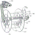
In order to orderly store and release the high pressure water pipe 900, referring to fig. 3 to 9, the storage pipe portion 200 is carried above the walking portion 100, and the storage pipe portion 200 has a first frame 210, a roller pipe wheel 220 rotatably disposed on the first frame 210, and a lead screw assembly 240. The high pressure water pipe 900 of this embodiment is a rubber hose, wherein the first frame 210 is carried by the running gear, so that the first frame 210 moves along with the running gear when the running gear moves.
As shown in fig. 3 to 7, the roll pipe reel 220 has an "i" shape structure, and includes two side reel bodies 222 and 223, a water passing rotation shaft 221 connecting the two side reel bodies 222 and 223, and a plurality of winding rollers 224 parallel to the water passing rotation shaft 221, the winding rollers 224 are connected between the two side reel bodies 222 and 223, and as shown in fig. 5 and 6, the six winding rollers 224 form one turn around the water passing rotation shaft 221 for winding a high pressure water pipe 900 (as shown in fig. 6).
As shown in fig. 5 and 7, the water rotation shaft 221 is opened with a water inlet 225 (shown in fig. 7) and a water outlet 226 (shown in fig. 5), the water inlet 225 is connected to the water outlet end of the high-pressure water pipe 900 through a connector, and the water outlet 226 is provided at the second end of the water rotation shaft and outputs high-pressure water from the high-pressure water pipe 900. Therefore, when the water passage rotation shaft 221 rotates counterclockwise in fig. 7, for example, the high-pressure water pipe 900 is wound around the winding roller 224, and when the water passage rotation shaft rotates clockwise, the high-pressure water pipe 900 is discharged.
In order to realize the rotation of the water passage rotating shaft 221, a second driving assembly is provided, and in this embodiment, as shown in fig. 6, the second driving assembly includes a roller pipe motor 230 and a chain wheel and chain transmission member, a chain wheel is installed on a first end portion of the water passage rotating shaft 221, and the roller pipe motor 230 transmits a torque to the water passage rotating shaft 221 through a chain to drive the water passage rotating shaft 211 to rotate together with the roller pipe wheel 220.
Further, in order to wind the high pressure water pipe 900 dispersedly around the wind roller 224 when the reel disk 220 rotates, as shown in fig. 5, a sprocket is also installed on the second end portion of the water rotation shaft 211, a sprocket is also installed on the end portion of the screw 242 parallel to the water rotation shaft 211 on the same side as the second end portion of the water rotation shaft 211, the sprocket of the second end portion of the water rotation shaft 211 and the sprocket of the end portion of the screw 242 are connected by a chain, the simultaneous linked rotation of the screw when the water rotation shaft 221 rotates is realized, a guide (not labeled) screwed to the screw 242 moves along the screw 242, and since the guide is used to guide the high pressure water pipe 900, the guide moves along the screw 242 while the water rotation shaft 221 rotates to wind the high pressure water pipe 900, the high pressure water pipe 900 is wound around the wind roller 224 in order, preferably, the lead of the screw 242 is equal to the pipe diameter of the high pressure water pipe 900, in this way, a uniform winding of the high-pressure water pipe 900 onto the winding roller 224 is achieved as the guide moves along the lead screw 242.
As shown in fig. 5 to 9, in one embodiment, the guide device includes a guide frame 244, a threaded block 246, a first guide wheel 247, and a second guide wheel 248, wherein the first guide wheel 247 and the second guide wheel 248 are both elastic rubber wheels. Specifically, the guide frame 244 includes two opposing side plates (not labeled). A screw block 246 is provided at the bottom of the guide frame 244, specifically, the screw block 246 is sandwiched at the bottom between the two opposite side plates and has a screw through hole (not shown) through which the lead screw 242 passes and is screw-coupled with the screw through hole. The first guide wheel 247 and the second guide wheel 248 are disposed on the guide frame 244, and particularly, may be respectively rotatably disposed between opposite side plates of the guide frame 244, the rotation axes of the first guide wheel 247 and the second guide wheel 248 are parallel, and a parallel gap is formed between the first guide wheel 247 and the second guide wheel 248, through which the high pressure water pipe 900 passes (as shown in fig. 7) for guiding the high pressure water pipe 900, and preferably, the second guide wheel 248 is located right above the first guide wheel 247.
Generally, the surfaces of the farm areas to be cleaned are dirty which are not easy to clean, and the dirty adhered to the surfaces are dissolved and softened by using a liquid medicine (such as a cleaning liquid, a disinfectant and the like), then the dirty is hit by using high-pressure water columns to wash away the dirty, and then the disinfectant is sprayed to perform disinfection treatment so as to achieve a higher biological safety level, so that in the embodiment, a plurality of liquid medicine tanks of different types of liquid medicines can be arranged, as shown in fig. 3, 5 and 6, two liquid medicine tanks including a liquid medicine tank B1 and a liquid medicine tank B2 are accommodated in the first frame 210. Of course, the number of the liquid medicine tanks is not limited to two as described above, and is not limited herein.
In order to draw out the liquid medicine and the high-pressure water in each liquid medicine tank, as shown in fig. 3 to 6, a siphon valve 400 is provided, and the siphon valve 400 includes at least one liquid inlet and a liquid outlet, in this embodiment, the liquid inlet of the siphon valve 400 includes at least a first inlet 410 for receiving the high-pressure water, a second siphon inlet 420 for receiving the first liquid medicine (e.g., from the liquid medicine tank B2), a third siphon inlet 430 for receiving the second liquid medicine (e.g., from the liquid medicine tank B1), and a liquid outlet 440 for outputting the high-pressure water or the mixed liquid of the high-pressure water and the liquid medicine. In this embodiment, the first inlet 410 is connected to the water outlet 226 of the water shaft 221 through a pipeline, the second siphon inlet 420 is connected to the liquid medicine tank B2 through a pipeline, and the third siphon inlet 430 is connected to the liquid medicine tank B1 through a pipeline.
Specifically, as shown in fig. 5 and 6, the water outlet 226 of the water rotation shaft 221 is connected to a first water inlet pipe b through a rotary joint (not labeled), the first water inlet pipe b is communicated with a second water inlet pipe c through a manual high-pressure ball valve 700, the second water inlet pipe c is communicated with a third water inlet pipe d through a high-pressure solenoid valve 800, the third water inlet pipe d is communicated with the first inlet 410, and the high-pressure water is automatically or manually cut off by using the high-pressure solenoid valve 800 and the high-pressure manual ball valve 700, and the protection function is also provided. In addition, only the pipeline of the chemical liquid tank B2 is taken as an example, the chemical liquid in the chemical liquid tank B2 is communicated with the second siphon inlet 420 through the chemical liquid inlet pipeline e, and a high pressure solenoid valve (not shown) may be connected to the chemical liquid inlet pipeline e to select the chemical liquid. The liquid outlet 440 outputs high pressure water or a mixture of high pressure water and liquid medicine through the water outlet pipeline.
The high pressure water pipe 900, the siphon valve 400, the pipes a-e, the liquid medicine tanks B1 and B2, the high pressure solenoid valve 800, the high pressure manual ball valve 700, and the like, as described above, form a liquid path piping system of the robot.
In order to selectively spray the high pressure water and the mixed liquid, the adjusting part 300 is provided, and the adjusting part 300 includes a second frame 310, and a support arm is provided on the second frame 310, and at least one water spray assembly is connected to the support arm, preferably one water spray assembly is connected to each of both ends of the support arm, wherein the second frame 310 is carried by the running gear, and the second frame 310 moves along with the running gear when the running gear moves. In the embodiment, the water spray assembly comprises an oscillating driving assembly and a switchable dual spray head, and the oscillating driving assembly drives the switchable dual spray head to oscillate by 360 degrees on a plane vertical to the supporting arm.
Specifically, as shown in fig. 10, 14 to 16, the swing driving assembly includes a swing motor 3383 and a worm gear box 338, the worm gear box 338 includes a worm 3381, a worm gear 3382 engaged with the worm 3381, and a swing pipe shaft (not shown) passing through the center of the worm gear 3382, wherein one end of the swing pipe shaft is connected to the switchable dual spray head 339, the other end thereof is communicated with the water outlet pipeline a through a rotary joint J (shown in fig. 11), an output shaft of the swing motor 3383 is connected to the worm 3381, the worm 3381 rotates to drive the worm gear 3382 to rotate on a plane perpendicular to the support arm, so that, when the swing motor 3383 is operated, the torque thereof is transmitted to the worm gear box 338, whereby the switchable spray head 339 can swing on a plane perpendicular to the support arm to adjust the spray angle of the switchable dual spray head 339. Preferably, the output shaft of swing motor 3383 is connected with worm 3381 through the flexible axle is long-range, and this kind of flexible transmission system can avoid swing motor 3383 to keep away from the region of easy contact water, reduces into water the risk, improves swing motor 3383 safety in utilization and reliability.
In order to realize the switching between the high pressure water sprayer 3392 and the foam sprayer 3393, as shown in fig. 15 and 16, the switchable dual sprayer 339 includes a switch 3391, a high pressure water sprayer 3392, and a foam sprayer 3393, and the switch 3391 includes an outer housing (not labeled), an inlet 33911, a first outlet 33912, a second outlet 33913, and a steel ball 33914, the inlet 33911 communicates with one end of the oscillating pipe shaft, the high pressure water sprayer 3392 is inserted at the first outlet 33911, the foam sprayer 3393 is inserted at the second outlet 33912, and the steel ball 33914 selectively blocks a flow path between the inlet 33911 and the first outlet 33912 or a flow path between the inlet 33911 and the second outlet 33913, so as to realize the ejection of high pressure water (water column) from the high pressure water sprayer 3392 or the ejection of foam generated from a mixture of high pressure water and a liquid medicine from the foam sprayer 33.
Specifically, as shown in fig. 10 and 16, when it is necessary to eject high-pressure water, the high-pressure water line through which high-pressure water flows is disconnected, the swing motor 3383 is controlled to operate, the switchable double nozzle 339 is adjusted from the position shown in fig. 10 to the horizontal position where the high-pressure water nozzle 3392 is located above and the foam nozzle 3393 is located below, that is, the switchable double nozzle 339 swings 90 ° counterclockwise, at this time, the steel ball 33914 falls into the second outlet 33912 by gravity, the foam nozzle 3393 is blocked, the high-pressure water line is opened, the steel ball 33914 is pressed by water pressure to be kept still and block the foam nozzle 3393, at this time, the high-pressure water is ejected from the high-pressure water nozzle 3392, and during the subsequent opening of the high-pressure water line, the switchable double nozzle 339 is swung by water pressure at this time, and the. Similarly, when foam needs to be sprayed, firstly, the foam pipeline for flowing the high-pressure water and the selected liquid medicine is disconnected, the swing motor 3383 is controlled to work, the switchable double spray head 339 is adjusted to the horizontal position where the foam spray head 3393 is located above and the high-pressure water spray head 3392 is located below from the position shown in fig. 10, namely, the switchable double spray head 339 swings 90 degrees clockwise, at this time, the steel ball 33914 falls into the first outlet 33911 under the action of gravity, the high-pressure water spray head 3392 is blocked, the foam pipeline is opened, the water pressure presses the steel ball 33914 to keep the steel ball 33914 immobile and continuously blocks the high-pressure water spray head 3392, at this time, the foam is sprayed from the foam spray head 3393, and during the later period that the foam pipeline is opened, no matter how the switchable double spray head 339 swings, the.
The automatic cleaning robot of the present embodiment automatically travels through the electric cabinet 500 (for example, according to a set route); when the high-pressure water pipe 900 needs to be stored, the pipe coiling motor 230 works to drive the water-passing rotating shaft 221 and the lead screw 242 to rotate in a linkage manner, the whole pipe coiling wheel disc 220 is driven to rotate, and the guide device moves on the lead screw 242, so that the high-pressure water pipe 900 is automatically wound on the winding roller 244 or discharged from the winding roller 244, and the high-pressure water pipe 900 is automatically stored; high-pressure water or mixed liquid can be output from the liquid outlet 440 of the siphon valve 400 by controlling the siphon valve 400, the high-pressure water or the mixed liquid is correspondingly sprayed out when different sprayers are switched by the switchable double sprayers 339, the switchable sprayers 339 can swing at multiple angles, various scene requirements are met, and the user experience is high; the robot has high automation degree, reduces the manual task amount, has high cleaning efficiency, and avoids the harm of severe cleaning environment to the health of human body.
Example two
In order to satisfy the multi-scenario use of the robot and enrich the multifunction of the robot, a pitch adjustment assembly 330 is provided in the embodiment to adjust the pitch angle of the switchable nozzle 339, the pitch adjustment assembly 330 includes a third driving assembly and a rotating connector, the rotating connector is sleeved on the supporting arm and is driven by the third driving assembly to rotate in linkage with the supporting arm, so as to realize the pitch angle of the switchable dual nozzle 339. Specifically, in this embodiment, the third driving assembly includes a pitching motor 331, a sprocket-chain transmission part (not labeled) and a gear transmission part (not labeled), the rotating link has a gear, and the torque of the pitching motor 331 is transmitted to the gear on the rotating link through the sprocket-chain transmission part and the gear transmission part, so that the rotating link and the supporting arm rotate in a linked manner.
In alternative embodiments, the rotational connecting member may also adopt other power transmission components, such as a belt transmission and the like, to receive the torque transmitted by the pitching motor 331, and the transmission between the pitching motor 331 and the rotating shaft may also be in the form of a gear-gear, a synchronous belt, a chain, a shaft coupling, a worm-worm gear, or a combination thereof, where the gear may be a spur gear, a helical gear, or a bevel gear, and the like, without limitation, as long as the torque of the pitching motor 331 can be transmitted to the rotational connecting member.
EXAMPLE III
In order to meet the multi-scene use of the robot, the multifunction of the robot is enriched, the length of the support arm is adjustable, so that the distance between the two water spray assemblies when the two ends of the support arm are both connected with the water spray assemblies can be adjusted, in the embodiment, as shown in fig. 10 to 13, the support arm comprises a left support arm part 334 and a right support arm part 335, the rotating connecting part comprises a left rotating connecting part 336 and a right rotating connecting part 337, the left rotating connecting part 336 is sleeved on the left support arm part 334, and one end of the left support arm part 334 is connected with a water spray assembly; the right pivotal connection piece 337 is sleeved on the right supporting arm portion 335, and one end of the right supporting arm portion 335 is connected to a water spraying assembly, wherein the left pivotal connection piece 337 and the right pivotal connection piece 338 simultaneously receive the torque transmitted by the pitching motor 331 through the sprocket-chain transmission part and the gear transmission part as described in the second embodiment.
As shown in fig. 10 and 11, the rectangular tube shaft 332 has one end inserted into the left rotary connector 336 and the other end inserted into the right rotary connector 337, and wraps a portion of the left support arm portion 334 passing through the left rotary connector 336 and a portion of the right support arm portion 335 passing through the right rotary connector 337, and in this embodiment, the left support arm portion 334 and the right support arm portion 335 are both square in cross-section and have an area equal to half of the cross-section area of the rectangular tube shaft 332, so that a portion of the left support arm portion 334 and a portion of the right support arm portion 335 are inserted into the rectangular tube shaft 332 in parallel and alternately, and a first rack gear 3341 and a second rack gear 3351 are formed on opposite sides of one end of the left support arm portion 334 and one end of the right support arm portion 335, respectively, as shown in fig. 12.
Referring again to fig. 12 and 13, in order to achieve synchronous telescoping of the left and right support arm portions 334 and 335, a gear assembly 333 is provided on the rectangular tubular shaft 332, the gear assembly 333 having a gear 3331, the gear 3331 being located within the rectangular tubular shaft 332 and engaging with both the first and second racks 3341 and 3351, and an output shaft of a telescoping motor (not shown) being connected to the gear 3331, the torque of the telescoping motor being transmitted to the gear 3331 when the telescoping motor is operated, the left and right support arm portions 334 and 335 being relatively synchronously shortened when the gear 3331 is rotated clockwise in fig. 12, for example, and the left and right support arm portions 334 and 335 being extended back synchronously when rotated counterclockwise, thereby achieving telescoping of the distance between the two water jet assemblies.
Preferably, the telescopic motor may be remotely connected to the gear 3331 through a flexible shaft, so that the telescopic motor may be disposed in the first frame 210 like the swing motor 3383, or elsewhere. The flexible transmission system can avoid the telescopic motor from being far away from the area which is easy to contact water, reduce the water inlet risk and improve the use safety and reliability of the telescopic motor.
Furthermore, in the present embodiment, when the pitch motor 331 transmits torque to the left and right rotational connectors 336 and 337 to rotate the left and right rotational connectors 336 and 337, the rectangular pipe shaft 332 rotates along with the rotation of the left and right rotational connectors 336 and 337 due to the existence of the rectangular pipe shaft 332, and the rotation of the rectangular pipe shaft 332 rotates the left and right support arm portions 334 and 335, so that the pitch angle adjustment of the switchable dual nozzle 339 can be realized.
Example four
In order to adjust the height of the switchable dual nozzle 339, in this embodiment, the second frame 310 is driven to move up and down by the lifting driving assembly 320, as shown in fig. 10, in this embodiment, the lifting driving assembly 320 includes a lifting motor 321, a worm gear-screw lifter 322, a screw 323 and a screw nut 324, the screw nut 34 is fixedly connected with the second frame 310 and is in threaded connection with the screw 323, when the lifting motor 321 works, the worm gear-screw lifter 322 is driven to drive the screw 323 to rotate, the screw nut 324 moves up and down along the screw 323, so that the second frame 310 fixedly connected with the screw nut 324 moves up and down in the length direction of the screw 323, thereby realizing the height, from the ground, of the switchable dual nozzle 339, the height of the switchable dual nozzle 339,
EXAMPLE five
In order to remotely control the movement of the robot, as shown in fig. 1, the present embodiment further includes a remote control device 600, the remote control device 600 communicates with a wireless receiving module (not shown) in the electric cabinet 500, and the remote control device 600 remotely transmits a remote control signal for operating the robot, for example, controlling the robot to perform cleaning according to a set route and a set work, controlling a traveling route of the robot, controlling switching of the switchable double collision heads 339, controlling spraying of high pressure water or foam, and the like.
The remote control device 600 is internally provided with a storage battery (not shown) and a wireless transmitting module (not shown), a surface panel (not shown) of the remote control device 600 comprises a switch, an emergency plug wire charging port, an electric quantity display and a touch screen, the switch controls the on-off of a circuit of the remote control device 600, the emergency plug wire charging port is used for off-line plug wire charging, the electric quantity display can check the real-time electric quantity, and a human-computer interaction interface is arranged in the touch screen to operate through human-computer interaction.
This remote control unit 600 detachably sets up on electric cabinet 500, and the position department that is used for placing this remote control unit 600 on electric cabinet 500 is equipped with the magnetism interface that charges (not shown), places remote control unit 600 in this position department, and power signal in electric cabinet 500 charges for this remote control unit 600 is automatic, and this remote control unit 600 magnetism adsorbs on electric cabinet 500, is difficult for losing, promotes user experience degree.
EXAMPLE six
In order to avoid the above problems and to achieve the tight and uniform retraction of the high pressure water pipe 900, when the high pressure water pipe 900 has a relatively high hardness, the high pressure water pipe 900 may be loosened, slipped or squeezed or stuck only by means of the screw assembly 240 and the pipe reeling disc 220, in a second embodiment, as shown in fig. 5, the guiding device is further provided with a first driving roller 243 and an auxiliary pipe reeling driving assembly, the auxiliary pipe reeling driving assembly includes an auxiliary pipe reeling motor 241 and a sprocket chain transmission member (not labeled), the auxiliary pipe reeling motor 241 transmits torque to the first driving roller 243 through the sprocket chain member, the first driving roller 243 is parallel to the screw 242 (preferably located right above the screw 242) and passes through the first guiding wheel 247, the first driving roller 247 rotates in conjunction with the first guiding wheel 247, and moves along the first driving roller due to the guiding frame 244 moving along the screw 242 while the first guiding wheel 247 rotates along with the first driving roller 243, such a linkage rotation may be achieved by configuring the shape of the cross section of the first driving roller 243 to be a regular polygon, and correspondingly configuring the hole wall of the center through hole of the first guide wheel 247 to be a matched regular polygon, but the manner of such linkage rotation is not limited thereto.
EXAMPLE seven
In the third embodiment, in order to reduce the friction between the first guide wheel 247 and the first driving roller 243 and make the guide device slide in the axial direction more smoothly, as shown in fig. 5 and 7, a guide roller 245 is further provided, both ends of the guide roller 245 are provided on the first frame 210 and are parallel to the lead screw 242 and the first driving roller 243, a circular arc groove 2441 is correspondingly provided on the top of the guide frame 244, a part of the outer side surface of the guide roller 245 is fitted into the circular arc groove 2441, and the guide device is assisted to travel in the axial direction of the lead screw 242.
Example eight
As shown in fig. 3, in the fourth embodiment, the first frame 210 is further provided with a limiting protection roller set 250 which is arranged in front of the guide device and corresponds to the gap between the first guide wheel 247 and the second guide wheel 248, the limiting protection roller set 250 comprises four protection rollers, two horizontal protection rollers which are parallel up and down and vertical protection rollers which are respectively arranged at two ends of the horizontal protection rollers, the high-pressure water pipe 900 passes through the parallel gap between the two horizontal protection rollers, and the vertical protection rollers prevent the high-pressure water pipe 900 from rubbing with surrounding components when the pipe collection starts, the pipe collection ends, the pipe release starts or the pipe release ends, so as to protect the high-pressure water pipe 900.
Example nine
In the fifth embodiment, as shown in fig. 4, a set of roll pipe protection roller sets 260 parallel to the water rotation shaft 221 is provided on the outer circumference of the roll pipe disk 220, and the roll pipe protection roller sets 260 include six protection rollers each disposed between opposite sides of the first frame 210 with a certain interval from the winding roller 224, the six protection rollers forming one turn around the roll pipe disk 220 for protecting and restraining the high pressure water pipe 900 when the high pressure water pipe 900 is wound onto the winding roller 224 so as to be compactly wound around the winding roller 224.
According to the automatic cleaning robot, the remote control device 600 can be used for realizing the remote operation of the robot, so that an operator can conveniently keep away from a severe cleaning environment, and the user experience is good; the switchable double-nozzle 399 can realize double-nozzle switching, switching of high-pressure water columns and various different liquid medicines, pitching angle adjustment, swinging angle adjustment and height adjustment, and the multifunctional robot can meet the use requirements in different scenes, so that the use range of the robot is expanded; distance measuring sensors are arranged around the robot, so that the distance of the obstacle is monitored in real time, the non-contact type guiding obstacle avoidance function is realized, and the use intellectualization of the robot is improved; the flexible transmission system is used, so that the water inlet risk of the power motor is reduced, and the use safety and reliability of the power motor are improved; the pipe coiling wheel disc 220 and the screw rod assembly 240 jointly realize the pipe coiling and uncoiling of the high-pressure water pipe 900, the high-pressure water pipe 900 is tightly and uniformly wound, and the walking and the coiling and uncoiling of the high-pressure water pipe 900 can be synchronized by automatically controlling the walking speed and the pipe coiling and uncoiling speed of the robot, so that the high-pressure water pipe 900 is synchronously paved, no water pipe is entangled, and the high-pressure water pipe 900 is prevented from being rolled by wheels; the robot is high in automation degree, manual operation is reduced, safety risks are reduced, and cleaning efficiency and effect are improved.
The above examples are only intended to illustrate the technical solution of the present invention, but not to limit it; although the present invention has been described in detail with reference to the foregoing embodiments, it will be apparent to those skilled in the art that various changes may be made and equivalents may be substituted for elements thereof; and such modifications or substitutions do not depart from the spirit and scope of the corresponding technical solutions.
Claims (10)
1. An automatic cleaning robot, comprising:
a first drive assembly;
a running gear driven by the first drive assembly;
a first frame carried by the running gear;
a second drive assembly;
the pipe coiling wheel disc is arranged on the first frame and comprises disc bodies on two sides, a water through rotating shaft connected with the two disc bodies and a plurality of winding rollers for winding a high-pressure water pipe, and the water through rotating shaft is driven by the second driving assembly to rotate and is communicated with a water outlet of the high-pressure water pipe;
the guide device is used for guiding the high-pressure water pipe when the high-pressure water pipe is retracted and released;
at least one liquid medicine box, wherein the liquid medicine in each liquid medicine box is different in type;
the siphon valve is provided with at least one liquid inlet and one liquid outlet, and each liquid inlet is respectively communicated with the water-through rotating shaft and each liquid medicine box;
a water spray assembly including a swing driving assembly and a switchable dual spray head driven by the swing driving assembly and swingable, the switchable dual spray head including a switcher, a high pressure water spray head, and a foam spray head, the switcher including a steel ball, an inlet, a first outlet, and a second outlet, the inlet communicating with a liquid outlet of the siphon valve, the high pressure water spray head being inserted at the first outlet, the foam spray head being inserted at the second outlet, the steel ball selectively blocking a flow path between the inlet and the first outlet or a flow path between the inlet and the second outlet;
a second frame carried by the running gear;
the supporting arm is arranged on the second frame, and at least one water spray assembly is connected to the supporting arm;
the electric cabinet is used for controlling the automatic cleaning robot to act;
and the power supply supplies power to all electric appliances in the automatic cleaning robot.
2. The robot of claim 1, further comprising a third drive assembly and a rotational link, wherein the rotational link is disposed on the support arm, and the third drive assembly drives the rotational link to rotate together with the support arm.
3. The automatic cleaning robot according to claim 2,
the support arm includes a left support arm portion and a right support arm portion;
the rotary connecting piece comprises a left rotary connecting piece and a right rotary connecting piece;
the left rotating connecting piece is sleeved on the left supporting arm part, and one end of the left supporting arm part is connected with the water spraying assembly;
the right rotating connecting piece is sleeved on the right supporting arm part, and one end of the right supporting arm part is connected with the water spraying assembly;
the third drive assembly drives the left and right pivotal connections to pivot in conjunction with the left and right support arm portions.
4. The automatic washing robot according to claim 3, characterized by further comprising:
a pipe shaft, one end of which is inserted into the left rotating connecting piece and the other end of which is inserted into the right rotating connecting piece, and the other end of the left supporting arm part and the other end of the right supporting arm part are both positioned in the pipe shaft, and the pipe shaft rotates together with the left rotating connecting piece and the right rotating connecting piece; a first rack is formed on one side surface of the other end of the left support arm portion, and a second rack opposite to the first rack is formed on one side surface of the other end of the right support arm portion;
a gear assembly fixed on the pipe shaft, wherein gears in the gear assembly are meshed with the first rack and the second rack;
and an output shaft of the telescopic motor is connected with the gear of the gear assembly.
5. The automatic washing robot as claimed in any one of claims 1 to 4, wherein said oscillating drive assembly comprises:
a swing motor;
a worm connected to an output shaft of the swing motor;
a worm gear engaged with the worm;
and the swinging pipe shaft is arranged in the center of the worm wheel in a penetrating manner, one end of the swinging pipe shaft is communicated with the inlet of the switcher, and the other end of the swinging pipe shaft is communicated with the liquid outlet of the siphon valve.
6. The robot of claim 5, wherein the swing motor is coupled to the worm by a flexible shaft.
7. The automatic cleaning robot according to any one of claims 1 to 4, further comprising a lifting drive assembly that drives the second frame to be lifted.
8. The automatic washing robot according to any one of claims 1 to 4, wherein the guide means comprises:
a guide frame;
the thread block is arranged at the bottom of the guide frame and is provided with a thread through hole, and the lead screw is in threaded connection with the thread hole;
an auxiliary reel pipe drive assembly;
the first driving roller is driven by the auxiliary roller pipe driving assembly to rotate, and the first driving roller is parallel to the lead screw and penetrates through the guide frame;
the first guide wheel is arranged in the guide frame and sleeved on the first driving roller, and the first guide wheel rotates along with the rotation of the first driving roller;
and the second guide wheel is rotatably arranged in the guide frame and is parallel to the first guide wheel, and the high-pressure water pipe penetrates through a gap between the first guide wheel and the second guide wheel.
9. The robot cleaner of claim 8, further comprising a guide roller disposed on the first frame and parallel to the first driving roller, wherein an arc groove is formed at a top of the guide frame, and a part of an outer surface of the guide roller is embedded in the arc groove.
10. The robot cleaner of any one of claims 1 to 4, further comprising a remote control device in communication with the wireless receiving module in the electrical cabinet, the remote control device remotely transmitting a remote control signal for actuating the robot cleaner.
Priority Applications (1)
| Application Number | Priority Date | Filing Date | Title |
|---|---|---|---|
| CN201911101743.7A CN111014131A (en) | 2019-11-12 | 2019-11-12 | Automatic cleaning robot |
Applications Claiming Priority (1)
| Application Number | Priority Date | Filing Date | Title |
|---|---|---|---|
| CN201911101743.7A CN111014131A (en) | 2019-11-12 | 2019-11-12 | Automatic cleaning robot |
Publications (1)
| Publication Number | Publication Date |
|---|---|
| CN111014131A true CN111014131A (en) | 2020-04-17 |
Family
ID=70205472
Family Applications (1)
| Application Number | Title | Priority Date | Filing Date |
|---|---|---|---|
| CN201911101743.7A Pending CN111014131A (en) | 2019-11-12 | 2019-11-12 | Automatic cleaning robot |
Country Status (1)
| Country | Link |
|---|---|
| CN (1) | CN111014131A (en) |
Cited By (10)
| Publication number | Priority date | Publication date | Assignee | Title |
|---|---|---|---|---|
| CN111468455A (en) * | 2020-04-21 | 2020-07-31 | 鞍山极致创新科技有限公司 | Pig farm excrement way cleaning robot |
| CN111468490A (en) * | 2020-04-29 | 2020-07-31 | 科立盈智能装备科技(广州)有限公司 | Jar body self-cleaning system |
| CN111644364A (en) * | 2020-06-16 | 2020-09-11 | 中铁环境科技工程有限公司 | Shield muck screening method |
| CN111921752A (en) * | 2020-07-09 | 2020-11-13 | 龙井和 | Industrial automatic spraying robot |
| WO2022048183A1 (en) * | 2020-09-07 | 2022-03-10 | 丰疆智能(深圳)有限公司 | Manure ditch cleaning device |
| WO2022122003A1 (en) * | 2020-12-11 | 2022-06-16 | 丰疆智能(深圳)有限公司 | Dung ditch cleaning machine and dung ditch cleaning method |
| CN114769195A (en) * | 2022-03-31 | 2022-07-22 | 河南云迹智能技术有限公司 | Automatic clear outdoor automatic sales counter |
| CN115250957A (en) * | 2022-08-08 | 2022-11-01 | 安徽农业大学 | Meat pigeon house convenient to it is clean |
| CN115501367A (en) * | 2022-10-19 | 2022-12-23 | 镇江市动物疫病预防控制中心 | Modernized livestock and poultry are bred and use environment degassing unit |
| WO2022271003A1 (en) * | 2021-06-25 | 2022-12-29 | Instituto Tecnológico y de Estudios Superiores de Monterrey | Remote-controlled reconfigurable multi-purpose modular robot |
-
2019
- 2019-11-12 CN CN201911101743.7A patent/CN111014131A/en active Pending
Cited By (13)
| Publication number | Priority date | Publication date | Assignee | Title |
|---|---|---|---|---|
| CN111468455A (en) * | 2020-04-21 | 2020-07-31 | 鞍山极致创新科技有限公司 | Pig farm excrement way cleaning robot |
| CN111468490A (en) * | 2020-04-29 | 2020-07-31 | 科立盈智能装备科技(广州)有限公司 | Jar body self-cleaning system |
| CN111644364A (en) * | 2020-06-16 | 2020-09-11 | 中铁环境科技工程有限公司 | Shield muck screening method |
| CN111644364B (en) * | 2020-06-16 | 2022-03-01 | 中铁环境科技工程有限公司 | Shield muck screening method |
| CN111921752A (en) * | 2020-07-09 | 2020-11-13 | 龙井和 | Industrial automatic spraying robot |
| CN111921752B (en) * | 2020-07-09 | 2021-10-15 | 陕西微阅信息技术有限公司 | Industrial automatic spraying robot |
| WO2022048183A1 (en) * | 2020-09-07 | 2022-03-10 | 丰疆智能(深圳)有限公司 | Manure ditch cleaning device |
| WO2022122003A1 (en) * | 2020-12-11 | 2022-06-16 | 丰疆智能(深圳)有限公司 | Dung ditch cleaning machine and dung ditch cleaning method |
| WO2022271003A1 (en) * | 2021-06-25 | 2022-12-29 | Instituto Tecnológico y de Estudios Superiores de Monterrey | Remote-controlled reconfigurable multi-purpose modular robot |
| CN114769195A (en) * | 2022-03-31 | 2022-07-22 | 河南云迹智能技术有限公司 | Automatic clear outdoor automatic sales counter |
| CN115250957A (en) * | 2022-08-08 | 2022-11-01 | 安徽农业大学 | Meat pigeon house convenient to it is clean |
| CN115250957B (en) * | 2022-08-08 | 2024-03-15 | 安徽农业大学 | Meat pigeon house convenient to clean |
| CN115501367A (en) * | 2022-10-19 | 2022-12-23 | 镇江市动物疫病预防控制中心 | Modernized livestock and poultry are bred and use environment degassing unit |
Similar Documents
| Publication | Publication Date | Title |
|---|---|---|
| CN111014131A (en) | Automatic cleaning robot | |
| EP1152656B1 (en) | Device for the cleaning of animal stalls | |
| CN211707513U (en) | Automatic cleaning robot | |
| CN210808938U (en) | Gardens are with spraying efficient novel two-way medicine and spray device | |
| CN210808632U (en) | Town road sewage discharging equipment | |
| CN211558568U (en) | Agricultural machine is with rotation type device of spraying insecticide | |
| WO2022122003A1 (en) | Dung ditch cleaning machine and dung ditch cleaning method | |
| JPH08290079A (en) | Rotary rocking sprinkler | |
| CN215530686U (en) | Excrement ditch cleaning machine | |
| CN211275776U (en) | High-pressure spraying cleaning machine | |
| CN212593204U (en) | Intelligent management unmanned spraying device | |
| CN212632166U (en) | Equipment pipe network structure is sprayed in atmosphere pollution control | |
| CN218499702U (en) | A sprinkler for vegetable greenhouse | |
| CN212937555U (en) | Mixed spraying equipment for agricultural planting | |
| CN210253426U (en) | High-rise water tank cleaning device | |
| CN214924478U (en) | But remote control's disinfection machine people | |
| CN218747765U (en) | Excrement ditch cleaning robot | |
| CN213587264U (en) | Vehicular insecticide sprinkler | |
| CN218188714U (en) | Fountain dust device | |
| CN214682510U (en) | Automatic pesticide spraying robot suitable for large-scale pig farm | |
| CN116832559B (en) | Construction dust fall equipment | |
| CN213926052U (en) | Environment-friendly watering device for municipal works | |
| CN215740686U (en) | Novel supply room nursing is with spraying device | |
| CN210020467U (en) | Center disinfection and spraying device for digestive endoscopy | |
| CN109548661A (en) | A kind of cleaning equipment improving livestock environment |
Legal Events
| Date | Code | Title | Description |
|---|---|---|---|
| PB01 | Publication | ||
| PB01 | Publication | ||
| SE01 | Entry into force of request for substantive examination | ||
| SE01 | Entry into force of request for substantive examination |