EP1437804A2 - Elektrischer Adapter - Google Patents
Elektrischer Adapter Download PDFInfo
- Publication number
- EP1437804A2 EP1437804A2 EP20030258240 EP03258240A EP1437804A2 EP 1437804 A2 EP1437804 A2 EP 1437804A2 EP 20030258240 EP20030258240 EP 20030258240 EP 03258240 A EP03258240 A EP 03258240A EP 1437804 A2 EP1437804 A2 EP 1437804A2
- Authority
- EP
- European Patent Office
- Prior art keywords
- base
- electrical
- terminals
- engagable
- adapter
- Prior art date
- Legal status (The legal status is an assumption and is not a legal conclusion. Google has not performed a legal analysis and makes no representation as to the accuracy of the status listed.)
- Granted
Links
Images


Classifications
-
- H—ELECTRICITY
- H01—ELECTRIC ELEMENTS
- H01R—ELECTRICALLY-CONDUCTIVE CONNECTIONS; STRUCTURAL ASSOCIATIONS OF A PLURALITY OF MUTUALLY-INSULATED ELECTRICAL CONNECTING ELEMENTS; COUPLING DEVICES; CURRENT COLLECTORS
- H01R31/00—Coupling parts supported only by co-operation with counterpart
- H01R31/06—Intermediate parts for linking two coupling parts, e.g. adapter
-
- A—HUMAN NECESSITIES
- A62—LIFE-SAVING; FIRE-FIGHTING
- A62B—DEVICES, APPARATUS OR METHODS FOR LIFE-SAVING
- A62B1/00—Devices for lowering persons from buildings or the like
- A62B1/06—Devices for lowering persons from buildings or the like by making use of rope-lowering devices
- A62B1/08—Devices for lowering persons from buildings or the like by making use of rope-lowering devices with brake mechanisms for the winches or pulleys
- A62B1/12—Devices for lowering persons from buildings or the like by making use of rope-lowering devices with brake mechanisms for the winches or pulleys hydraulically operated
-
- A—HUMAN NECESSITIES
- A62—LIFE-SAVING; FIRE-FIGHTING
- A62B—DEVICES, APPARATUS OR METHODS FOR LIFE-SAVING
- A62B1/00—Devices for lowering persons from buildings or the like
- A62B1/06—Devices for lowering persons from buildings or the like by making use of rope-lowering devices
- A62B1/18—Other single parts for rope lowering-devices, e.g. take-up rollers for ropes, devices for shooting ropes
-
- B—PERFORMING OPERATIONS; TRANSPORTING
- B65—CONVEYING; PACKING; STORING; HANDLING THIN OR FILAMENTARY MATERIAL
- B65H—HANDLING THIN OR FILAMENTARY MATERIAL, e.g. SHEETS, WEBS, CABLES
- B65H75/00—Storing webs, tapes, or filamentary material, e.g. on reels
- B65H75/02—Cores, formers, supports, or holders for coiled, wound, or folded material, e.g. reels, spindles, bobbins, cop tubes, cans, mandrels or chucks
- B65H75/34—Cores, formers, supports, or holders for coiled, wound, or folded material, e.g. reels, spindles, bobbins, cop tubes, cans, mandrels or chucks specially adapted or mounted for storing and repeatedly paying-out and re-storing lengths of material provided for particular purposes, e.g. anchored hoses, power cables
- B65H75/38—Cores, formers, supports, or holders for coiled, wound, or folded material, e.g. reels, spindles, bobbins, cop tubes, cans, mandrels or chucks specially adapted or mounted for storing and repeatedly paying-out and re-storing lengths of material provided for particular purposes, e.g. anchored hoses, power cables involving the use of a core or former internal to, and supporting, a stored package of material
- B65H75/40—Cores, formers, supports, or holders for coiled, wound, or folded material, e.g. reels, spindles, bobbins, cop tubes, cans, mandrels or chucks specially adapted or mounted for storing and repeatedly paying-out and re-storing lengths of material provided for particular purposes, e.g. anchored hoses, power cables involving the use of a core or former internal to, and supporting, a stored package of material mobile or transportable
- B65H75/403—Carriage with wheels
-
- B—PERFORMING OPERATIONS; TRANSPORTING
- B65—CONVEYING; PACKING; STORING; HANDLING THIN OR FILAMENTARY MATERIAL
- B65H—HANDLING THIN OR FILAMENTARY MATERIAL, e.g. SHEETS, WEBS, CABLES
- B65H75/00—Storing webs, tapes, or filamentary material, e.g. on reels
- B65H75/02—Cores, formers, supports, or holders for coiled, wound, or folded material, e.g. reels, spindles, bobbins, cop tubes, cans, mandrels or chucks
- B65H75/34—Cores, formers, supports, or holders for coiled, wound, or folded material, e.g. reels, spindles, bobbins, cop tubes, cans, mandrels or chucks specially adapted or mounted for storing and repeatedly paying-out and re-storing lengths of material provided for particular purposes, e.g. anchored hoses, power cables
- B65H75/38—Cores, formers, supports, or holders for coiled, wound, or folded material, e.g. reels, spindles, bobbins, cop tubes, cans, mandrels or chucks specially adapted or mounted for storing and repeatedly paying-out and re-storing lengths of material provided for particular purposes, e.g. anchored hoses, power cables involving the use of a core or former internal to, and supporting, a stored package of material
- B65H75/44—Constructional details
- B65H75/4481—Arrangements or adaptations for driving the reel or the material
- B65H75/4489—Fluid motors
-
- H—ELECTRICITY
- H01—ELECTRIC ELEMENTS
- H01R—ELECTRICALLY-CONDUCTIVE CONNECTIONS; STRUCTURAL ASSOCIATIONS OF A PLURALITY OF MUTUALLY-INSULATED ELECTRICAL CONNECTING ELEMENTS; COUPLING DEVICES; CURRENT COLLECTORS
- H01R13/00—Details of coupling devices of the kinds covered by groups H01R12/70 or H01R24/00 - H01R33/00
- H01R13/648—Protective earth or shield arrangements on coupling devices, e.g. anti-static shielding
- H01R13/652—Protective earth or shield arrangements on coupling devices, e.g. anti-static shielding with earth pin, blade or socket
-
- H—ELECTRICITY
- H01—ELECTRIC ELEMENTS
- H01R—ELECTRICALLY-CONDUCTIVE CONNECTIONS; STRUCTURAL ASSOCIATIONS OF A PLURALITY OF MUTUALLY-INSULATED ELECTRICAL CONNECTING ELEMENTS; COUPLING DEVICES; CURRENT COLLECTORS
- H01R24/00—Two-part coupling devices, or either of their cooperating parts, characterised by their overall structure
- H01R24/28—Coupling parts carrying pins, blades or analogous contacts and secured only to wire or cable
- H01R24/30—Coupling parts carrying pins, blades or analogous contacts and secured only to wire or cable with additional earth or shield contacts
-
- H—ELECTRICITY
- H01—ELECTRIC ELEMENTS
- H01R—ELECTRICALLY-CONDUCTIVE CONNECTIONS; STRUCTURAL ASSOCIATIONS OF A PLURALITY OF MUTUALLY-INSULATED ELECTRICAL CONNECTING ELEMENTS; COUPLING DEVICES; CURRENT COLLECTORS
- H01R13/00—Details of coupling devices of the kinds covered by groups H01R12/70 or H01R24/00 - H01R33/00
- H01R13/58—Means for relieving strain on wire connection, e.g. cord grip, for avoiding loosening of connections between wires and terminals within a coupling device terminating a cable
- H01R13/5841—Means for relieving strain on wire connection, e.g. cord grip, for avoiding loosening of connections between wires and terminals within a coupling device terminating a cable allowing different orientations of the cable with respect to the coupling direction
-
- H—ELECTRICITY
- H01—ELECTRIC ELEMENTS
- H01R—ELECTRICALLY-CONDUCTIVE CONNECTIONS; STRUCTURAL ASSOCIATIONS OF A PLURALITY OF MUTUALLY-INSULATED ELECTRICAL CONNECTING ELEMENTS; COUPLING DEVICES; CURRENT COLLECTORS
- H01R2103/00—Two poles
Definitions
- the present invention relates to main power electrical connectors. More particularly, although not exclusively, the invention relates to a main power electrical adapter having a choice of configurations.
- Electric plugs for insertion to wall sockets are of course known. These either comprise two or three pins, depending upon whether an earth pin is needed.
- the plugs have a power cord extending therefrom, usually directly outwardly from the wall, or otherwise in a direction parallel to the wall in a downward or downward and angularly-offset manner.
- this pre-set angle at which the power cord extends from the plug body is inconvenient. For example, when the cord extends normally to the wall and it is desired to place furniture against the wall at that position, the furniture must often need to be spaced from the wall.
- the plug If the power cord is short and extends downwardly from the plug when the plug is inserted into the wall socket, this can create problems where say it extends from a desk lamp for example to be positioned at a higher level than that of the wall socket. In such a situation, it would be more appropriate that the plug have the power cord extending upwardly instead of downwardly therefrom.
- the invention comprises an electrical adapter for use in countries having mains electrical pin/socket patterns that allow no alternative plug-insertion orientations, comprising:
- the invention comprises an electrical adapter comprising:
- the invention comprises an electrical adapter comprising:
- the base has conducting pins extending from one side thereof for insertion into apertures of a mating socket and the electrical terminals are located on the other side of the base and correspond to each of the conducting pins and are connected electrically thereto.
- the base can have extending therefrom another power cord at a remote end of which there is a plug having conducting pins for insertion into apertures of a mating socket and wherein the electrical terminals are connected electrically to each of the conducting pins via individual conductors in said another power cord.
- the engagable and engager pivot mounting features are mutually bayonet-inter-engagable.
- the engagable pivot mounting features of the base comprise a number of radially extending lugs having circumferentially extending ramp surfaces.
- the engager pivot mounting features of the body comprise openings through which the lugs must pass for interengagement of the base and the body to take place.
- said lugs are of differing size and said openings are of corresponding differing size to restrict allowable alignment orientations of the body and base when interconnected.
- the base comprises an annular channel within which the terminals are located.
- the terminals are located within narrowed parts of the channel.
- the body includes a locking device by which the base is locked to the body when interconnected therewith.
- the electrical contacts of the body are spring-biased toward the terminals.
- the electrical contacts of the body are connected to individual conductors of a power cord extending from the body.
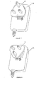
- FIGS 1 and 2 depict the adapter base 10.
- the adapter base 10 is fabricated typically as a moulding of plastics material and includes a plate 13 having three projecting metallic electrically conductive pins projecting from one side. There are active and neutral pins 11 and an earth pin 12. Alternatively, there might simply be a pair of active and neutral pins. As yet a further alternative, the pin 12 might be a plastics or other non-conductive dummy pin.
- the adapter base 10 of the illustrated embodiment has its pins configured in the standard British layout, but it should be appreciated that the pin configuration could equally be that of Australia, the USA, or any other country. Indeed, the plug body 20 of Figures 3 and 4 might be supplied with a number of bases 10, each base having a configuration applicable for a different country.
- a flat bearing ring 14 formed as an integral moulding therewith.
- annular channel 9 having a pair of diametrically opposed narrowed portions 8.
- One of the terminals is connected electrically with either the active or neutral pin 11 and the other terminal is connected to the other pin 11.
- the outer rail 15 has extending therefrom four bayonet lugs 16.
- Each bayonet lug 16 is spaced from the bearing surface 14 and includes a circumferentially extending ramped upper surface. Diametrically opposed pairs of the bayonet lugs 16 are of the same size, yet adjacent pairs of the bayonet lugs are of differing size.
- FIGS 3 and 4 depict a plug body 20 for bayonet-inter-connection with the adapter base 10.
- the plug body 20 is typically fabricated from several plastics moulded parts that are screwed, snapped or welded together ultrasonically and has extending from it via a rubber grommet 22 a power cord 21.
- the plug body 20 includes a flat circular bearing ring 33 for engagement with the bearing ring 14 of the adapter base 10. There is a central recess 32 in which there is located a pair of diametrically opposed electrical spring contacts 26. These spring contacts are connected electrically with individual conductors within the cord 21. Located around the central recess 32 there are four openings 31. Diametrically opposed pairs of the openings 31 are of the same size, whereas adjacent pairs are of different size. By this arrangement, bayonet lugs of the adapter base 10 can be lowered into the openings 31 of the plug body 20 in only two possible orientations, namely those as depicted in Figures 5 and 6 respectively.
- the openings 31 are just large enough to receive the lugs and the larger pair of the four lugs will not fit into the smaller openings.
- each opening 31 and situated beneath the bearing ring 33 are lug-receiving slots 29. There are ramp surfaces at the bottom of each opening 31.
- a locking device comprising an interlock tongue 24 and an activator 23 formed integrally therewith.
- the tongue 24 projects into a tongue recess 25 as depicted in Figure 4.
- the outer rail 15 includes a pair of diametrically opposed interlock recesses 18 into one of which the tongue 24 snap-engages upon bayonet-fitting of the two components.
- the activator 23 is an integral part of the plug body 20 and has a pair of cut-outs at either side enabling downward movement of the interlocked tongue 24 upon application of finger-pressure to the activator 23. It is only upon this application of finger pressure that the interlocked parts can be detached.
- parts 10 and 20 are attached as shown in Figure 5 and 6 and then the adapter based 10 is rotated clockwise until the bayonet lugs bear against end walls 28 at each slot 29. At this time, the interlock tongue 24 snaps into one of the interlock recesses 18, depending upon the chosen orientation as depicted in either of Figures 7 or 8.
- the attached components can then be plugged into a wall socket, plug board, or extension cord for example.
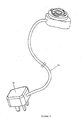
- the base of the electrical adapter need not the configured with pins to be received directly by apertures of a mating socket.
- the base might have an extension cord 35 extending therefrom and at the remote end of which there is a standard plug 36 to be received by a wall socket or another extension cord for example.
- the body might be formed integrally with an electrical appliance, double adapter, multiple plug board, transformer box or the like.
Landscapes
- General Health & Medical Sciences (AREA)
- Business, Economics & Management (AREA)
- Emergency Management (AREA)
- Health & Medical Sciences (AREA)
- Details Of Connecting Devices For Male And Female Coupling (AREA)
- Connector Housings Or Holding Contact Members (AREA)
- Coupling Device And Connection With Printed Circuit (AREA)
- Dry Shavers And Clippers (AREA)
- Cable Accessories (AREA)
- Portable Nailing Machines And Staplers (AREA)
- Liquid Developers In Electrophotography (AREA)
- Surgical Instruments (AREA)
- Structure And Mechanism Of Cameras (AREA)
Applications Claiming Priority (2)
| Application Number | Priority Date | Filing Date | Title |
|---|---|---|---|
| GB0300098 | 2003-01-03 | ||
| GBGB0300098.1A GB0300098D0 (en) | 2003-01-03 | 2003-01-03 | Electrical adaptor |
Publications (3)
| Publication Number | Publication Date |
|---|---|
| EP1437804A2 true EP1437804A2 (de) | 2004-07-14 |
| EP1437804A3 EP1437804A3 (de) | 2005-11-02 |
| EP1437804B1 EP1437804B1 (de) | 2010-01-20 |
Family
ID=9950640
Family Applications (1)
| Application Number | Title | Priority Date | Filing Date |
|---|---|---|---|
| EP03258240A Expired - Lifetime EP1437804B1 (de) | 2003-01-03 | 2003-12-30 | Elektrischer Adapter |
Country Status (10)
| Country | Link |
|---|---|
| US (1) | US6942508B2 (de) |
| EP (1) | EP1437804B1 (de) |
| JP (2) | JP4508658B2 (de) |
| KR (1) | KR101015494B1 (de) |
| CN (1) | CN100449883C (de) |
| AT (1) | ATE456174T1 (de) |
| DE (1) | DE60331039D1 (de) |
| GB (1) | GB0300098D0 (de) |
| HK (1) | HK1067797A1 (de) |
| TW (1) | TWI303504B (de) |
Cited By (7)
| Publication number | Priority date | Publication date | Assignee | Title |
|---|---|---|---|---|
| WO2007113541A2 (en) * | 2006-04-03 | 2007-10-11 | Thinplug Limited | Electrical plug with a rotatable pin |
| EP1845590A1 (de) * | 2006-04-11 | 2007-10-17 | Modern Sense Ltd | Universelle Batterielader und/oder Spannung Stecker |
| EP1942562A2 (de) | 2007-01-08 | 2008-07-09 | Modern Sense Limited | Universeller Stromadapter/-wandler |
| WO2008113634A1 (de) * | 2007-03-21 | 2008-09-25 | Illinois Tool Works Inc. | Verlängerungskabel und daran adaptierte rohrbearbeitungsvorrichtung |
| EP2413437A3 (de) * | 2010-07-26 | 2013-03-20 | Delta Electronics, Inc. | Drehbarer Stecker und elektronische Vorrichtung mit solch einem drehbaren Stecker |
| US9653839B2 (en) | 2013-02-28 | 2017-05-16 | Phoenix Contact Gmbh & Co. Kg | Industrial electrical plug connector |
| US9853390B2 (en) | 2014-03-05 | 2017-12-26 | Phoenix Contact Gmbh & Co. Kg | Housing for a plug-type connector |
Families Citing this family (34)
| Publication number | Priority date | Publication date | Assignee | Title |
|---|---|---|---|---|
| TWI262634B (en) * | 2005-09-16 | 2006-09-21 | Hon Hai Prec Ind Co Ltd | Power supply devices and electronic products using the same |
| US20100120278A1 (en) * | 2005-10-26 | 2010-05-13 | Yang chun-lian | Multi-angular power adapter |
| TWI273752B (en) * | 2006-02-07 | 2007-02-11 | Leader Electronics Inc | Power source plug with changeable direction |
| EP1830186A1 (de) * | 2006-03-01 | 2007-09-05 | ETH Zürich | Vorrichtung für Hochdurchsatzanalyse auf Zellbasis |
| US7273384B1 (en) | 2006-04-11 | 2007-09-25 | Modern Sense Limited | Universal battery charger and/or power adaptor |
| US20080064244A1 (en) * | 2006-09-08 | 2008-03-13 | Bryan Holland | Plug adapter with pivotally mounted prongs |
| JP4950694B2 (ja) * | 2007-02-19 | 2012-06-13 | パナソニック株式会社 | ランプソケット及び照明器具 |
| TWM321168U (en) * | 2007-03-02 | 2007-10-21 | Billion Electric Co Ltd | Power adapter module with rotatable plug, power supply and electric apparatus with said power adapter module or said power supply |
| FR2928494A1 (fr) * | 2008-03-07 | 2009-09-11 | Swiss Hitech Asia Ltd | Adaptateur universel d'alimentation electrique |
| US8197260B2 (en) | 2008-03-07 | 2012-06-12 | Belkin International, Inc. | Electrical connector and method of manufacturing same |
| US20090225486A1 (en) | 2008-03-07 | 2009-09-10 | Belkin International, Inc. | Electrical Connector And Method Of Manufacturing Same |
| US7896702B2 (en) * | 2008-06-06 | 2011-03-01 | Apple Inc. | Compact power adapter |
| US7632137B1 (en) * | 2008-07-28 | 2009-12-15 | Cheng Uei Precision Industry Co., Ltd. | Power adapter |
| US7601023B1 (en) * | 2008-08-07 | 2009-10-13 | Cheng Uei Precision Industry Co., Ltd. | Power adapter |
| US7632119B1 (en) * | 2008-08-11 | 2009-12-15 | Cheng Uei Precision Industry Co., Ltd. | Power adapter |
| US8934261B2 (en) | 2008-12-23 | 2015-01-13 | Apple Inc. | Compact device housing and assembly techniques therefor |
| US7993164B2 (en) * | 2008-12-31 | 2011-08-09 | Hewlett-Packard Development Company, L.P. | Compact power adapter with interchangeable heads |
| TWM359782U (en) * | 2009-01-06 | 2009-06-21 | Unifive Technology Co Ltd | An adjustable power transformer |
| TWM359781U (en) * | 2009-01-06 | 2009-06-21 | Unifive Technology Co Ltd | A detachable power transformer |
| US8272899B2 (en) * | 2009-07-10 | 2012-09-25 | Research In Motion Limited | Electrical charger with base unit and adaptor unit |
| TWI385875B (zh) * | 2009-10-07 | 2013-02-11 | Leader Electronics Inc | The plug can be changed in direction and replaceable power converter |
| TWI427875B (zh) * | 2009-10-28 | 2014-02-21 | Powertech Ind Co Ltd | 具有旋轉及摺合的插頭 |
| US8052441B2 (en) * | 2010-01-11 | 2011-11-08 | Hewlett-Packard Development Company, L.P. | Plug module |
| JP5515176B2 (ja) * | 2010-05-21 | 2014-06-11 | 古河電工パワーシステムズ株式会社 | コネクタおよびコネクタセット |
| TWI413320B (zh) * | 2010-12-14 | 2013-10-21 | Hon Hai Prec Ind Co Ltd | 一種可換插頭的電源適配器 |
| TWM426181U (en) * | 2011-09-22 | 2012-04-01 | Leader Electronics Inc | Power plug apparatus capable of changing directions |
| CN103166037B (zh) * | 2011-12-15 | 2017-02-01 | 富泰华工业(深圳)有限公司 | 移动电源 |
| TWM461255U (zh) * | 2013-04-02 | 2013-09-01 | Hon Hai Prec Ind Co Ltd | 電源適配器 |
| WO2015111068A1 (en) | 2014-01-24 | 2015-07-30 | Remus Daniel | An electrical female receptacle with safety mechanism in multi-plug adapter and wall sockets |
| TWI639283B (zh) | 2017-08-08 | 2018-10-21 | 碩天科技股份有限公司 | 配接器及其使用方法 |
| KR102557113B1 (ko) * | 2018-04-14 | 2023-07-18 | 가부시키가이샤 아스타리스쿠 | 커넥터 및 접속 어댑터 |
| USD936020S1 (en) * | 2019-04-30 | 2021-11-16 | Design Pool Limited | Wall adapter |
| CN112490754A (zh) * | 2019-09-12 | 2021-03-12 | 比亚迪股份有限公司 | 充电锁紧机构、充电口、车辆及充电设备 |
| US11283224B1 (en) * | 2020-10-12 | 2022-03-22 | Ademco Inc. | Adapter mechanism |
Citations (2)
| Publication number | Priority date | Publication date | Assignee | Title |
|---|---|---|---|---|
| US6139359A (en) * | 1999-04-08 | 2000-10-31 | Snap-On Tools Company | Cordless screwdriver and multi-position battery pack therefor |
| DE19932942A1 (de) * | 1999-07-14 | 2001-03-15 | Tyco Electronics Logistics Ag | HF-Winkelsteckverbinder |
Family Cites Families (9)
| Publication number | Priority date | Publication date | Assignee | Title |
|---|---|---|---|---|
| TW269751B (en) | 1994-02-24 | 1996-02-01 | Asian Micro Sources Inc | Interchangeable plug device for power supply |
| CN2253877Y (zh) * | 1996-04-09 | 1997-05-07 | 周义雄 | 具有旋转功能的电插头 |
| US5702259A (en) * | 1996-08-12 | 1997-12-30 | Lee; Chiu-Shan | Safety socket and plug arrangement |
| US6062884A (en) * | 1998-09-11 | 2000-05-16 | Hybrinetics, Inc. | Rotationally activated multiple plug receptacle adapter |
| GB2366087B (en) * | 2000-08-09 | 2004-05-26 | Chiu-Shan Lee | Universal electric adapter |
| US6669495B2 (en) * | 2000-11-06 | 2003-12-30 | Research In Motion Limited | Universal adapter with interchangeable plugs |
| KR100396207B1 (ko) * | 2001-02-06 | 2003-09-03 | 김병준 | 회전식 플러그를 갖는 어댑터 |
| TWI243519B (en) * | 2001-05-31 | 2005-11-11 | Primax Electronics Ltd | Socket which can be tightly connected with a plug |
| CN2519498Y (zh) * | 2001-12-13 | 2002-10-30 | 陈苍意 | 旋转插头 |
-
2003
- 2003-01-03 GB GBGB0300098.1A patent/GB0300098D0/en not_active Ceased
- 2003-12-30 EP EP03258240A patent/EP1437804B1/de not_active Expired - Lifetime
- 2003-12-30 AT AT03258240T patent/ATE456174T1/de not_active IP Right Cessation
- 2003-12-30 DE DE60331039T patent/DE60331039D1/de not_active Expired - Lifetime
- 2003-12-31 US US10/749,964 patent/US6942508B2/en not_active Expired - Lifetime
-
2004
- 2004-01-02 TW TW093100066A patent/TWI303504B/zh not_active IP Right Cessation
- 2004-01-02 KR KR1020040000050A patent/KR101015494B1/ko not_active IP Right Cessation
- 2004-01-02 CN CNB2004100012024A patent/CN100449883C/zh not_active Expired - Fee Related
- 2004-01-05 JP JP2004000622A patent/JP4508658B2/ja not_active Expired - Fee Related
- 2004-12-21 HK HK04110105.7A patent/HK1067797A1/xx not_active IP Right Cessation
-
2009
- 2009-04-10 JP JP2009095665A patent/JP2009187955A/ja active Pending
Patent Citations (2)
| Publication number | Priority date | Publication date | Assignee | Title |
|---|---|---|---|---|
| US6139359A (en) * | 1999-04-08 | 2000-10-31 | Snap-On Tools Company | Cordless screwdriver and multi-position battery pack therefor |
| DE19932942A1 (de) * | 1999-07-14 | 2001-03-15 | Tyco Electronics Logistics Ag | HF-Winkelsteckverbinder |
Cited By (9)
| Publication number | Priority date | Publication date | Assignee | Title |
|---|---|---|---|---|
| WO2007113541A2 (en) * | 2006-04-03 | 2007-10-11 | Thinplug Limited | Electrical plug with a rotatable pin |
| WO2007113541A3 (en) * | 2006-04-03 | 2007-11-29 | Zihni Yalcin | Electrical plug with a rotatable pin |
| EP1845590A1 (de) * | 2006-04-11 | 2007-10-17 | Modern Sense Ltd | Universelle Batterielader und/oder Spannung Stecker |
| EP1942562A2 (de) | 2007-01-08 | 2008-07-09 | Modern Sense Limited | Universeller Stromadapter/-wandler |
| EP1942562A3 (de) * | 2007-01-08 | 2009-11-18 | Modern Sense Limited | Universeller Stromadapter/-wandler |
| WO2008113634A1 (de) * | 2007-03-21 | 2008-09-25 | Illinois Tool Works Inc. | Verlängerungskabel und daran adaptierte rohrbearbeitungsvorrichtung |
| EP2413437A3 (de) * | 2010-07-26 | 2013-03-20 | Delta Electronics, Inc. | Drehbarer Stecker und elektronische Vorrichtung mit solch einem drehbaren Stecker |
| US9653839B2 (en) | 2013-02-28 | 2017-05-16 | Phoenix Contact Gmbh & Co. Kg | Industrial electrical plug connector |
| US9853390B2 (en) | 2014-03-05 | 2017-12-26 | Phoenix Contact Gmbh & Co. Kg | Housing for a plug-type connector |
Also Published As
| Publication number | Publication date |
|---|---|
| GB0300098D0 (en) | 2003-02-05 |
| ATE456174T1 (de) | 2010-02-15 |
| KR101015494B1 (ko) | 2011-02-22 |
| KR20040062886A (ko) | 2004-07-09 |
| EP1437804B1 (de) | 2010-01-20 |
| US6942508B2 (en) | 2005-09-13 |
| TW200417090A (en) | 2004-09-01 |
| TWI303504B (en) | 2008-11-21 |
| HK1067797A1 (en) | 2005-04-15 |
| CN100449883C (zh) | 2009-01-07 |
| CN1518169A (zh) | 2004-08-04 |
| JP2009187955A (ja) | 2009-08-20 |
| JP2004214206A (ja) | 2004-07-29 |
| EP1437804A3 (de) | 2005-11-02 |
| DE60331039D1 (de) | 2010-03-11 |
| JP4508658B2 (ja) | 2010-07-21 |
| US20050074996A1 (en) | 2005-04-07 |
Similar Documents
| Publication | Publication Date | Title |
|---|---|---|
| US6942508B2 (en) | Electrical adapter | |
| US8480418B2 (en) | Electrical charger locking assembly | |
| AU2006202331B2 (en) | Universal battery charger and/or power adaptor | |
| US6669495B2 (en) | Universal adapter with interchangeable plugs | |
| US6231358B1 (en) | Electrical plug and receptacle having safety features | |
| US6592386B2 (en) | Socket which can be tightly connected with a plug | |
| TWI399002B (zh) | 具易連能力的模組式連接器 | |
| US5540596A (en) | Electric plug for supplying current to electric appliances | |
| EP4181328A1 (de) | Modulare auswechselbare steckdosenstruktur | |
| CN101431205A (zh) | 具有结合臂的转接头结构 | |
| CN106981801A (zh) | 适配器组件 | |
| EP1845590B1 (de) | Universelles Batterieladegerät und/oder Netzadapter | |
| EP0257482A1 (de) | Elektrische Steckerstifte | |
| CN219979872U (zh) | 一种连接器壳体及连接器 | |
| CN116157979A (zh) | 插口感应充电设备 | |
| GB2219472A (en) | Branching adaptors on electrical connectors | |
| TWM624117U (zh) | 電源轉接裝置 | |
| TWM531083U (zh) | 對應適用於雙系統通用序列匯流排之連接器 | |
| GB2480867A (en) | Electrical power lead |
Legal Events
| Date | Code | Title | Description |
|---|---|---|---|
| PUAI | Public reference made under article 153(3) epc to a published international application that has entered the european phase |
Free format text: ORIGINAL CODE: 0009012 |
|
| AK | Designated contracting states |
Kind code of ref document: A2 Designated state(s): AT BE BG CH CY CZ DE DK EE ES FI FR GB GR HU IE IT LI LU MC NL PT RO SE SI SK TR |
|
| AX | Request for extension of the european patent |
Extension state: AL LT LV MK |
|
| 17P | Request for examination filed |
Effective date: 20050107 |
|
| REG | Reference to a national code |
Ref country code: HK Ref legal event code: DE Ref document number: 1067797 Country of ref document: HK |
|
| PUAL | Search report despatched |
Free format text: ORIGINAL CODE: 0009013 |
|
| AK | Designated contracting states |
Kind code of ref document: A3 Designated state(s): AT BE BG CH CY CZ DE DK EE ES FI FR GB GR HU IE IT LI LU MC NL PT RO SE SI SK TR |
|
| AX | Request for extension of the european patent |
Extension state: AL LT LV MK |
|
| AKX | Designation fees paid |
Designated state(s): AT BE BG CH CY CZ DE DK EE ES FI FR GB GR HU IE IT LI LU MC NL PT RO SE SI SK TR |
|
| 17Q | First examination report despatched |
Effective date: 20071102 |
|
| GRAP | Despatch of communication of intention to grant a patent |
Free format text: ORIGINAL CODE: EPIDOSNIGR1 |
|
| GRAS | Grant fee paid |
Free format text: ORIGINAL CODE: EPIDOSNIGR3 |
|
| GRAA | (expected) grant |
Free format text: ORIGINAL CODE: 0009210 |
|
| AK | Designated contracting states |
Kind code of ref document: B1 Designated state(s): AT BE BG CH CY CZ DE DK EE ES FI FR GB GR HU IE IT LI LU MC NL PT RO SE SI SK TR |
|
| REG | Reference to a national code |
Ref country code: GB Ref legal event code: FG4D |
|
| REG | Reference to a national code |
Ref country code: CH Ref legal event code: EP |
|
| REG | Reference to a national code |
Ref country code: IE Ref legal event code: FG4D |
|
| REF | Corresponds to: |
Ref document number: 60331039 Country of ref document: DE Date of ref document: 20100311 Kind code of ref document: P |
|
| REG | Reference to a national code |
Ref country code: HK Ref legal event code: GR Ref document number: 1067797 Country of ref document: HK |
|
| REG | Reference to a national code |
Ref country code: NL Ref legal event code: VDEP Effective date: 20100120 |
|
| PG25 | Lapsed in a contracting state [announced via postgrant information from national office to epo] |
Ref country code: AT Free format text: LAPSE BECAUSE OF FAILURE TO SUBMIT A TRANSLATION OF THE DESCRIPTION OR TO PAY THE FEE WITHIN THE PRESCRIBED TIME-LIMIT Effective date: 20100120 |
|
| PG25 | Lapsed in a contracting state [announced via postgrant information from national office to epo] |
Ref country code: NL Free format text: LAPSE BECAUSE OF FAILURE TO SUBMIT A TRANSLATION OF THE DESCRIPTION OR TO PAY THE FEE WITHIN THE PRESCRIBED TIME-LIMIT Effective date: 20100120 Ref country code: ES Free format text: LAPSE BECAUSE OF FAILURE TO SUBMIT A TRANSLATION OF THE DESCRIPTION OR TO PAY THE FEE WITHIN THE PRESCRIBED TIME-LIMIT Effective date: 20100501 Ref country code: PT Free format text: LAPSE BECAUSE OF FAILURE TO SUBMIT A TRANSLATION OF THE DESCRIPTION OR TO PAY THE FEE WITHIN THE PRESCRIBED TIME-LIMIT Effective date: 20100520 |
|
| PG25 | Lapsed in a contracting state [announced via postgrant information from national office to epo] |
Ref country code: SI Free format text: LAPSE BECAUSE OF FAILURE TO SUBMIT A TRANSLATION OF THE DESCRIPTION OR TO PAY THE FEE WITHIN THE PRESCRIBED TIME-LIMIT Effective date: 20100120 Ref country code: FI Free format text: LAPSE BECAUSE OF FAILURE TO SUBMIT A TRANSLATION OF THE DESCRIPTION OR TO PAY THE FEE WITHIN THE PRESCRIBED TIME-LIMIT Effective date: 20100120 |
|
| PG25 | Lapsed in a contracting state [announced via postgrant information from national office to epo] |
Ref country code: SE Free format text: LAPSE BECAUSE OF FAILURE TO SUBMIT A TRANSLATION OF THE DESCRIPTION OR TO PAY THE FEE WITHIN THE PRESCRIBED TIME-LIMIT Effective date: 20100120 Ref country code: EE Free format text: LAPSE BECAUSE OF FAILURE TO SUBMIT A TRANSLATION OF THE DESCRIPTION OR TO PAY THE FEE WITHIN THE PRESCRIBED TIME-LIMIT Effective date: 20100120 Ref country code: CY Free format text: LAPSE BECAUSE OF FAILURE TO SUBMIT A TRANSLATION OF THE DESCRIPTION OR TO PAY THE FEE WITHIN THE PRESCRIBED TIME-LIMIT Effective date: 20100120 Ref country code: GR Free format text: LAPSE BECAUSE OF FAILURE TO SUBMIT A TRANSLATION OF THE DESCRIPTION OR TO PAY THE FEE WITHIN THE PRESCRIBED TIME-LIMIT Effective date: 20100421 Ref country code: RO Free format text: LAPSE BECAUSE OF FAILURE TO SUBMIT A TRANSLATION OF THE DESCRIPTION OR TO PAY THE FEE WITHIN THE PRESCRIBED TIME-LIMIT Effective date: 20100120 Ref country code: BE Free format text: LAPSE BECAUSE OF FAILURE TO SUBMIT A TRANSLATION OF THE DESCRIPTION OR TO PAY THE FEE WITHIN THE PRESCRIBED TIME-LIMIT Effective date: 20100120 |
|
| PLBE | No opposition filed within time limit |
Free format text: ORIGINAL CODE: 0009261 |
|
| STAA | Information on the status of an ep patent application or granted ep patent |
Free format text: STATUS: NO OPPOSITION FILED WITHIN TIME LIMIT |
|
| PG25 | Lapsed in a contracting state [announced via postgrant information from national office to epo] |
Ref country code: BG Free format text: LAPSE BECAUSE OF FAILURE TO SUBMIT A TRANSLATION OF THE DESCRIPTION OR TO PAY THE FEE WITHIN THE PRESCRIBED TIME-LIMIT Effective date: 20100420 Ref country code: SK Free format text: LAPSE BECAUSE OF FAILURE TO SUBMIT A TRANSLATION OF THE DESCRIPTION OR TO PAY THE FEE WITHIN THE PRESCRIBED TIME-LIMIT Effective date: 20100120 Ref country code: CZ Free format text: LAPSE BECAUSE OF FAILURE TO SUBMIT A TRANSLATION OF THE DESCRIPTION OR TO PAY THE FEE WITHIN THE PRESCRIBED TIME-LIMIT Effective date: 20100120 |
|
| 26N | No opposition filed |
Effective date: 20101021 |
|
| PG25 | Lapsed in a contracting state [announced via postgrant information from national office to epo] |
Ref country code: DK Free format text: LAPSE BECAUSE OF FAILURE TO SUBMIT A TRANSLATION OF THE DESCRIPTION OR TO PAY THE FEE WITHIN THE PRESCRIBED TIME-LIMIT Effective date: 20100120 |
|
| PGFP | Annual fee paid to national office [announced via postgrant information from national office to epo] |
Ref country code: IE Payment date: 20110128 Year of fee payment: 8 |
|
| PG25 | Lapsed in a contracting state [announced via postgrant information from national office to epo] |
Ref country code: MC Free format text: LAPSE BECAUSE OF NON-PAYMENT OF DUE FEES Effective date: 20101231 |
|
| REG | Reference to a national code |
Ref country code: CH Ref legal event code: PL |
|
| PG25 | Lapsed in a contracting state [announced via postgrant information from national office to epo] |
Ref country code: CH Free format text: LAPSE BECAUSE OF NON-PAYMENT OF DUE FEES Effective date: 20101231 Ref country code: LI Free format text: LAPSE BECAUSE OF NON-PAYMENT OF DUE FEES Effective date: 20101231 |
|
| REG | Reference to a national code |
Ref country code: IE Ref legal event code: MM4A |
|
| PG25 | Lapsed in a contracting state [announced via postgrant information from national office to epo] |
Ref country code: LU Free format text: LAPSE BECAUSE OF NON-PAYMENT OF DUE FEES Effective date: 20101230 Ref country code: HU Free format text: LAPSE BECAUSE OF FAILURE TO SUBMIT A TRANSLATION OF THE DESCRIPTION OR TO PAY THE FEE WITHIN THE PRESCRIBED TIME-LIMIT Effective date: 20100721 |
|
| PG25 | Lapsed in a contracting state [announced via postgrant information from national office to epo] |
Ref country code: TR Free format text: LAPSE BECAUSE OF FAILURE TO SUBMIT A TRANSLATION OF THE DESCRIPTION OR TO PAY THE FEE WITHIN THE PRESCRIBED TIME-LIMIT Effective date: 20100120 Ref country code: IE Free format text: LAPSE BECAUSE OF NON-PAYMENT OF DUE FEES Effective date: 20111230 |
|
| PGFP | Annual fee paid to national office [announced via postgrant information from national office to epo] |
Ref country code: GB Payment date: 20141224 Year of fee payment: 12 |
|
| PGFP | Annual fee paid to national office [announced via postgrant information from national office to epo] |
Ref country code: FR Payment date: 20141208 Year of fee payment: 12 |
|
| PGFP | Annual fee paid to national office [announced via postgrant information from national office to epo] |
Ref country code: IT Payment date: 20141126 Year of fee payment: 12 |
|
| PGFP | Annual fee paid to national office [announced via postgrant information from national office to epo] |
Ref country code: DE Payment date: 20141223 Year of fee payment: 12 |
|
| REG | Reference to a national code |
Ref country code: DE Ref legal event code: R119 Ref document number: 60331039 Country of ref document: DE |
|
| GBPC | Gb: european patent ceased through non-payment of renewal fee |
Effective date: 20151230 |
|
| REG | Reference to a national code |
Ref country code: FR Ref legal event code: ST Effective date: 20160831 |
|
| PG25 | Lapsed in a contracting state [announced via postgrant information from national office to epo] |
Ref country code: GB Free format text: LAPSE BECAUSE OF NON-PAYMENT OF DUE FEES Effective date: 20151230 Ref country code: DE Free format text: LAPSE BECAUSE OF NON-PAYMENT OF DUE FEES Effective date: 20160701 |
|
| PG25 | Lapsed in a contracting state [announced via postgrant information from national office to epo] |
Ref country code: FR Free format text: LAPSE BECAUSE OF NON-PAYMENT OF DUE FEES Effective date: 20151231 |
|
| PG25 | Lapsed in a contracting state [announced via postgrant information from national office to epo] |
Ref country code: IT Free format text: LAPSE BECAUSE OF NON-PAYMENT OF DUE FEES Effective date: 20151230 |