EP1437686A2 - Objektinformationsverarbeitungsvorrichtung, Bildverarbeitungssystem, Spielvorrichtung und Bildverarbeitungsverfahren - Google Patents
Objektinformationsverarbeitungsvorrichtung, Bildverarbeitungssystem, Spielvorrichtung und Bildverarbeitungsverfahren Download PDFInfo
- Publication number
- EP1437686A2 EP1437686A2 EP03257805A EP03257805A EP1437686A2 EP 1437686 A2 EP1437686 A2 EP 1437686A2 EP 03257805 A EP03257805 A EP 03257805A EP 03257805 A EP03257805 A EP 03257805A EP 1437686 A2 EP1437686 A2 EP 1437686A2
- Authority
- EP
- European Patent Office
- Prior art keywords
- object information
- pixel
- image data
- section
- extracted
- Prior art date
- Legal status (The legal status is an assumption and is not a legal conclusion. Google has not performed a legal analysis and makes no representation as to the accuracy of the status listed.)
- Withdrawn
Links
Images







Classifications
-
- G—PHYSICS
- G06—COMPUTING OR CALCULATING; COUNTING
- G06T—IMAGE DATA PROCESSING OR GENERATION, IN GENERAL
- G06T7/00—Image analysis
- G06T7/20—Analysis of motion
- G06T7/246—Analysis of motion using feature-based methods, e.g. the tracking of corners or segments
-
- G—PHYSICS
- G06—COMPUTING OR CALCULATING; COUNTING
- G06T—IMAGE DATA PROCESSING OR GENERATION, IN GENERAL
- G06T7/00—Image analysis
- G06T7/10—Segmentation; Edge detection
- G06T7/194—Segmentation; Edge detection involving foreground-background segmentation
-
- G—PHYSICS
- G06—COMPUTING OR CALCULATING; COUNTING
- G06T—IMAGE DATA PROCESSING OR GENERATION, IN GENERAL
- G06T7/00—Image analysis
- G06T7/70—Determining position or orientation of objects or cameras
-
- G—PHYSICS
- G06—COMPUTING OR CALCULATING; COUNTING
- G06T—IMAGE DATA PROCESSING OR GENERATION, IN GENERAL
- G06T2207/00—Indexing scheme for image analysis or image enhancement
- G06T2207/10—Image acquisition modality
- G06T2207/10016—Video; Image sequence
-
- G—PHYSICS
- G06—COMPUTING OR CALCULATING; COUNTING
- G06T—IMAGE DATA PROCESSING OR GENERATION, IN GENERAL
- G06T2207/00—Indexing scheme for image analysis or image enhancement
- G06T2207/30—Subject of image; Context of image processing
- G06T2207/30221—Sports video; Sports image
Definitions
- the present invention relates to an object information processing apparatus for processing input image data to obtain information about an object contained in the image, an image processing system having a function of recognizing the object contained in the image using the object information, and a game apparatus and an image processing method using the image processing system.
- Camera modules are utilized to input image data.
- Such an image data input method can handle a large amount of information simultaneously and therefore is considerably efficient compared to data input methods which employ a key board, a jog dial, a joystick or the like to input operating commands.
- input image data is typically displayed as an input image on a monitor screen, and subsequently a final process, i.e., various judgment (store or send data, etc.) is performed by a human.
- the user performs actual movements in order to enhance virtual reality.
- a number of techniques for sensing movements have been developed. Particularly, if the movements of the user can be input as image data into an image processing system so that the movements can be recognized, this technique may be useful for game apparatuses.
- the central processing unit (CPU) of a computer needs to be used to eventually recognize the movements of the user. Before the eventual recognition, it is necessary to extract required information from the image data. Conventionally, a number of techniques for extracting an object from image data have been proposed.
- an object recognition apparatus for recognizing a moving object has been proposed in Japanese Laid-Open Publication No. 6-266841.
- a stationary object is detected in image data by feature extraction; background data is obtained; and the background data is subtracted from current image data to recognize a moving object.
- Japanese Laid-Open Publication No. 63-88684 discloses an object recognition method, in which a luminosity gradient vector is calculated based on the luminosity concentrations of adjacent pixels, and a difference in angle of the luminosity gradient vector is used to recognize an object.
- Japanese Laid-Open Publication No. 59-132075 discloses an image processing apparatus, in which only the contour of an object is stored in an image memory before recognition is performed by a central processing unit in order to reduce a processing time required for recognition.
- Japanese Laid-Open Publication No. 6-266841 requires a memory for storing a large amount of data for each step of object feature extraction, stationary object recognition, background data calculation, image subtraction, and moving object recognition. These steps require a large computation amount. Moreover, if real-time processing is required for the step, a high-performance CPU or processing operation circuit needs to be employed.
- image data needs to be stored in order to compare image data between adjacent pixels during processing operations, and therefore, an image memory for storing at least one frame of image data is required.
- an object information processing apparatus for obtaining object information from input image data comprising pixels, which comprises: an object determination section for determining whether or not each pixel is a part of an object to be extracted by comparing color information indicating a color of the pixel with a predetermined reference value for the object; and an object information retaining section for retaining coordinate data of the pixel as the object information if the pixel has been determined by the object determination section to be a part of the object to be extracted.
- the object determination section comprises: a first to an n th comparison sections for determining whether or not the color information of eachpixel of the input image satisfies a first to an n th object conditions, respectively (n: natural integer); and an AND circuit for receiving n outputs of the first to the n th comparison sections.
- the object information processing further comprises: an image data conversion section provided before the object determination section, for converting an UYVY value of the input image data to an HSV value.
- the object determination section compares the HSV value of each pixel output by the image data conversion section with the predetermined reference value to determine whether or not the pixel is a part of the object to be extracted.
- the image data conversion section has a first conversion table for converting an UV value of the input image data to an H (hue) value, and a second conversion table for converting the UV value of the input image data to an S (saturation) value, and the image data conversion section outputs a Y value of the input image as a V (lightness) value.
- the object information processing apparatus further comprises: a noise removal section for removing noise from a result of determination by the object determination section.
- the noise removal section comprises: a shift resistor section for successively retaining the result of determination by the object determination section; and a noise removal determination section for determining whether or not a predetermined number or more of a plurality of results of the shift resistor section are equal to one another to determine whether or not the plurality of results are noise.
- an object inclusion relation determination section for determining whether a pixel of the input image data which has been determined by the object determination section to be a part of an object to be extracted is a part of an already detected object or of a new object which has not been detected, and generating coordinate data of the pixel.
- the object information retaining section retains the coordinate data generated by the object inclusion relation determination section for each detected object.
- the object inclusion relation determination section generates four coordinate points: coordinates having maximum X, coordinates having minimum X, coordinates having maximum Y, and coordinates having minimum Y, where coordinates of the object are (X, Y).
- the object inclusion relation determination section determines whether or not there is another pixel satisfying the same object condition, and when there is another pixel satisfying the same object condition, the other pixel is determined to be a part of the object and the coordinate data (X, Y) of the object is updated.
- the object determination section determines that there is no pixel satisfying the same object condition
- the pixel is determined to be a part of a newly detected object and information about the pixel is stored in the object information retaining section corresponding to the newly detected object.
- the object information retaining section retains a condition matching flag indicating which object condition is satisfied as a part of the object information.
- the object information retaining section retains one frame of object information of an object which has been determined to be an object to be extracted.
- an image processing system which comprises: the above-described object information processing apparatus; an image data output apparatus for outputting image data into the object information processing apparatus; and a control apparatus for controlling the object information processing apparatus and the image data output apparatus.
- the image data output apparatus is provided with an image pickup device for taking an object image, and coordinate data of the object indicating a location of the object is coordinate data on the image pickup device.
- control apparatus comprises a processing operation section for reading out object information stored in the object information processing apparatus and performing a processing operation for recognizing an object contained in image data.
- the processing operation section reads out the object information from the object information processing apparatus on a frame-by-frame basis.
- the processing operation section reads out the object information, which has been extracted on a frame-by-frame basis, from the object information processing apparatus and compares the object information between frames to detect movement or change of an object.
- control apparatus recognizes that the object is moving in a predetermined direction when coordinate data of the object is changed in the predetermined direction between each of a plurality of consecutive frames.
- control apparatus recognizes that the object is looming toward a viewing site when a coordinate location of the object is not changed and a size of the object is expanding between each of a plurality of consecutive frames in coordinate data of the object.
- control apparatus recognizes that the object is moving away from a viewing site when a coordinate location of the object is not changed and a size of the object is shrinking between each of a plurality of consecutive frames in coordinate data of the object.
- the control apparatus when the object has at least two colors, the control apparatus recognizes a behavior of the object when each color of the object is moved between each of a plurality of consecutive frames.
- a game apparatus which recognizes a behavior of an object using the above-described image processing system, is provided.
- an image processing method comprises the steps of: outputting image data from an image data output apparatus to an object information processing apparatus; converting a UYVY value of the input image data to an HSV value using the object information processing apparatus, comparing the HSV value of each pixel with a reference value provided for an object to be extracted to determine whether or not the pixel is a part of the object to be extracted, and storing coordinate data of the pixel which has been determined to be a part of the object to be extracted as object information on an object-by-object basis; and reading the object information stored in the object information processing apparatus using a processing operation section of a control apparatus on a frame-by-frame basis and recognizing an object contained in image data based on the object information.
- the processing operation section of the control apparatus reads out the object information, which has been extracted on a frame-by-frame basis, from the object information processing apparatus and compares the object information between each frame to detect movement or change of an object.
- image data from the image data output section (e.g., a camera module, etc. ) is serially processed by the object information processing apparatus on a pixel-by-pixel basis, and the coordinate data of an object to be extracted is stored in the object information storing section of the object information processing apparatus.
- image data itself is not stored in a memory. Only the coordinate data of an object to be extracted is stored. Therefore, in the present invention, a large-capacity memory, such as a frame memory, a line memory or the like, is not required.
- Object information, such as coordinate data or the like, stored in the object information storing section is rewritten as appropriate. In some cases, all data may be rewritten in the object information storing section. Therefore, it is preferable that a resistor in which all bits can be simultaneously accessed is used instead of a memory device, such as RAM or the like.
- an object contained in an image is extracted by comparing a value indicated by color information contained in image data with a reference value using the object information processing apparatus. Therefore, as is different from conventional techniques, complicated processing flow using a CPU for object extraction or the like is not required.
- the coordinate data of an extracted object can be used to recognize the object contained in an image using the processing operation section, such as a CPU, a processing operation circuit or the like. Therefore, image processing load on the image processing operation section can be significantly reduced.
- a large-capacity memory for storing image data is not required.
- a relative low-performance CPU, processing operation circuit or the like can be used. Therefore, the size and cost of an image processing system capable of recognizing an object can be significantly reduced.
- An object can be recognized from an image by a method for determining the shape of the object, a method for determining a difference in color of images, and a combination thereof.
- an object is recognized based on the color of its image.
- the image data conversion section converts the UYVY value of image data output by the image data output section to the object information processing apparatus to an HSV value, and it is preferably determined whether or not image data is a part of an object to be extracted, based on the HSV value.
- Hue (H) and saturation (S) are typically represented by a color wheel having 0 degrees to 360 degrees. Hue is represented by an angle on the color wheel and saturation is represented by a size (distance) from the center of the color wheel. Therefore, a color can be specified as follows: for example, "a hue is between 10 degrees to 20 degrees and a saturation is 10 or more".
- a UV value represents color information in a two-dimensional coordinate system. It is possible to specify a color with a UV value. However, it is not easy to determine a UV value range which matches the sensitivity of a human. In order to specify a color range which matches the sensitivity of a human, the color range is preferably represented by an area on a disk defined by an angle and a size (radius).
- the UYVY value-HSV value conversion is performed using a conversion table.
- the UYVY value-HSV value conversion can be completed in a clock cycle of an image transfer clock signal and can be thus performed in real time without using a fast clock signal.
- Analog signals such as images taken by a camera module or the like, contain noise or ambiguous signals. Therefore, it is preferable to provide a noise removal section which removes noise from the results of determination by the object determination section.
- An object which the object determination section determines is to be extracted may be a part of an already detected object. Therefore, it is preferable that the object inclusion relation determination section determines whether the object is a part of the already detected object or a new object which has not been detected so far.
- the object inclusion relation determination section generates data indicating the coordinates having maximum X, the coordinates having minimum X, the coordinates having maximum Y, and the coordinates having minimum Y, of coordinates (X, Y). Objects can be recognized using data of the four coordinate points, thereby making it possible to further reduce the amount of data.
- the information of an object stored in the object information storing section can be read out by the processing operation section on a frame-by-frame basis. Therefore, the object information storing section (e.g., a resistor, etc. ) stores only one frame of coordinate data of an object which is determined to be an object to be extracted, thereby making it possible to reduce the amount of data to be stored.
- the object information storing section e.g., a resistor, etc.
- the processing operation section reads out the coordinate data of an object from the object information storing section on a frame-by-frame basis, and the coordinate data of the object is compared between each frame, thereby making it possible to detect movement or change of the object.
- the coordinate data of an object can be temporarily retained in a resistor instead of a memory, so that the retained coordinate data can be compared with input data of the next frame to detect movement or change of an object.
- the invention described herein makes possible the advantage of providing an object information processing apparatus capable of obtaining information required for object recognition in few types and in small quantities; an image processing system capable of relatively easily recognizing an object and detecting movement or change of an object using the object information; a game apparatus and an image processing method using the same.
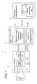
- Figure 1 is a block diagram showing a major configuration of an image processing system according to an embodiment of the present invention.
- an image processing system 1 comprises a camera module 2 as an image data output device, an object extraction LSI 3 as an object information processing device, and a one-chip microcomputer 4 which is a control device for controlling the camera module 2 and the object extraction LSI 3 .
- the camera module 2 comprises a lens 21 , an image pickup device 22 (e.g., a CCD, a CMOS imager, etc.), and an image processing DSP 23 .
- an image pickup device 22 e.g., a CCD, a CMOS imager, etc.
- an image processing DSP 23 e.g., a CCD, a CMOS imager, etc.
- the image processing DSP 23 performs communication via an interface circuit (not shown), such as an I2C bus or the like. Such an interface circuit is often not incorporated in the inexpensive one-chip microcomputer 4 .
- the object extraction LSI 3 is provided with a camera module controlling bus interface circuit 31 described below.
- the object extraction LSI 3 comprises the camera module controlling bus interface circuit 31 for interfacing between the camera module 2 and the one-chip micro computer 4 and an object information extraction circuit 32 .
- the object information extraction circuit 32 compares, for each pixel, a value indicated by color information contained in image data output by the camera module 2 with a reference value for an object to be extracted to determine whether or not an object is to be extracted. When it is determined that an object is to be extracted, the coordinate data of the object to be extracted is stored.
- the object extraction LSI 3 has a small circuit scale, and therefore, can be incorporated into the image processing DSP 23 or the one-chip microcomputer 4 of the camera module 2 .
- the object extraction LSI 3 is a discrete unit so that a general-purpose camera module 2 and one-chip microcomputer 4 can be used to construct a system.
- the one-chip microcomputer 4 comprises a CPU 41 as a control section, a ROM 42 as a memory section, and the like.
- the ROM 42 stores an image processing control program.
- the camera module 2 and the object extraction LSI 3 are controlled in accordance with the image processing control program stored in the ROM 42 to recognize an object contained in an image and detect movement or change of the object.
- the one-chip microcomputer 4 is connected to an input setting section (not shown). The user appropriately enters inputs via the input setting section to provide settings for the camera module 2 and the object extraction LSI 4.
- an image data output format, a gain, a white balance, and the like are set.
- the object extraction LSI 3 reference values of the hue (H), saturation (S) andlightness (Y) of an object to be extracted, reference values for determining the inclusion relation of an object, and the like are set.
- the following extraction condition may be provided: "an object has a hue in the range from 20 degrees to 30 degrees, a saturation in the range of 50% or more, and a lightness in the range of 30% or more. Two objects are determined to be the same if the distance therebetween is within 3 pixels".
- the number of extraction conditions is not limited to one. A plurality of extraction conditions may be provided.
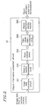
- Figure 2 is a block diagram showing a major configuration of the object information extraction circuit 32 of Figure 1 .
- the object information extraction circuit 32 comprises an image data conversion circuit 321 as an image data conversion section, an object extraction condition determination circuit 322 as a determination section, a noise removal circuit 323 as a noise removal section, an object inclusion relation determination circuit 324 as an object inclusion relation determination section, and an object information storing register 325 as an object information storing section (object information storing section).
- the image data conversion circuit 321 format-converts the UYVY value of image data output by the camera module 2 to an HSV value.
- the HSV value of each pixel output by the image data conversion circuit 321 is compared with a reference value given to an object to be extracted to determine whether or not input image data contains an object to be extracted.
- the noise removal circuit 323 removes noise based on the result of determination by the extraction condition determination circuit 322 .
- the object inclusion relation determination circuit 324 determines whether an object which has been determined to be an object to be extracted is a part of an object which has been already extracted or a new object which has not been extracted.
- the object inclusion relation determination circuit 324 produces coordinate data of the object.
- the coordinate data of an object includes the coordinates having maximum X, the coordinates having minimum X, the coordinates having maximum Y and the coordinates having minimum Y, of the object.
- the object information storing register 325 stores the coordinate data of each object which has been determined to be an object to be extracted.
- one frame of coordinate data is stored in the object information storing register 325 for each object which has been determined to be an object to be extracted.
- a resistor is used as the object information storing section 325 . The reason will be described below.
- extracted object information is rewritten if required, and all extracted object information may be rewritten at a time. Therefore, a resistor is preferably used, in which all bits can be simultaneously assessed.
- Memory devices such as RAM and the like, have high gate efficiency, however, the number of bits which can be simultaneously accessed via an I/O portion is limited. Therefore, in this embodiment, a resistor is used to construct an object information storing section.
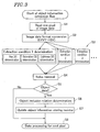
- Figure 3 is a flowchart showing a control flow of object information extraction by the object information extraction circuit 32 of Figure 2 .
- step S1 image data (UYVY) output by the camera module 2 is input to the image data conversion circuit 321 of the object extraction LSI 3 on a pixel-by-pixel basis.
- step S2 the image data format conversion is performed.
- the image data conversion circuit 321 performs format conversion of the UYVY value of color information contained in input image data to an HSV value.
- the reason the UYVY value of input image data is converted to an HSV value is that a hue (H) and a saturation (S) are represented by an angle and a size (distance) from the center of a color wheel ranging from 0 degrees to 360 degrees, and it is easy to specify a range based on the sensitivity of a human.
- step S3 extraction conditions are determined.
- the extraction condition determination circuit 322 compares an HSV value output by the image data conversion circuit 321 with a reference value given to an object to be extracted on a pixel-by-pixel basis to determine whether or not input image data contains an object to be extracted.
- the object information extraction flow has no feedback due to a conditional branch or the like and proceeds to subsequent steps straightforwardly. Therefore, it is possible to readily construct a circuit capable of performing extraction condition determination processes having different conditions in parallel.
- step S4 noise removal is performed.
- the noise removal circuit 323 removes noise from the result of determination by the extraction condition determination circuit 322 .
- step S5 it is determined whether or not data is a part of an object to be extracted, based on the result of determination by the extraction condition determination circuit 322 from which noise has been removed. If the data is determined to be a part of an object to be extracted in step S5 (Yes), the process goes to step S6. On the other hand, if the data is determined not to be a part of an object to be extracted in step S5 (No), the process goes to step S8 and the next pixel data is processed.
- step S6 object inclusion relation is determined.
- the object inclusion relation determination circuit 324 determines whether an object which has been determined in step S5 to be an object to be extracted is a part of an object which has been already extracted or a new object which has not been extracted.
- the object inclusion relation determination circuit 324 produces coordinate data of the object.
- step S7 values stored in the object information storing register 325 are updated.
- the coordinate data of each object which has been determined to be an object to be extracted is newly retained. Thereafter, the process goes to step S8 where the next pixel data is processed.
- step S2 The image data format conversion in step S2 and the image data conversion circuit 321 of Figure 2 will be described in detail.
- Figure 4 is a diagram for explaining the image data conversion of the image data conversion circuit 321 of Figure 2 .
- the image data conversion circuit 321 has a conversion table for converting a (U, V) value of input image data to an H value representing a hue and a conversion table for converting a (U, V) value of input image data to an S value representing a saturation.
- An H value and an S value which have been obtained by the image data conversion circuit 321 are supplied to the extraction condition determination circuit 322 .
- a lightness (Y value) of image data input to the image data conversion circuit 321 is supplied as a V value to the extraction condition determination circuit 322 .
- the above-described data conversion from a UYVY value to an HSV value contains multiplication and the like. Therefore, the data conversion is not completed by one cycle if a conventional processing operation is employed.
- an image memory such as a frame memory or the like, is not used, so that image data is not stored in an image memory, and therefore, each process has to be performed in real time.
- an image data conversion method requiring a plurality of cycles is not preferable, and image data conversion has to be completed in one cycle.
- the image data conversion circuit 321 is provided with the conversion table between UYVY values and HSV values so that input values and output values have a one-to-one relationship, thereby making it possible to complete image data conversion in one cycle.
- one cycle refers to a cycle of a clock which is used for image data format conversion.
- the object information extraction circuit 32 does not generate a clock and the image data format conversion is performed in synchronization with image data UYVY transferred from the image processing DSP 23 of the camera module 2 .
- One cycle is herein defined based on a time point and period in which one pixel of image data is transferred unless otherwise dictated.
- step S3 the extraction condition determination in step S3 and the extraction condition determination circuit 322 of Figure 2 will be described in detail.
- Figure 5 is a block diagram showing a concrete exemplary configuration of the extraction condition determination circuit 322 of Figure 2 .
- the extraction condition determination circuit 322 comprises a comparison circuit 322a and a multi-input AND circuit 322A for determining whether or not a condition 0 for object extraction is satisfied; a comparison circuit 322b and a multi-input AND circuit 322B for determining whether or not another condition 1 for object extraction is satisfied; a comparison circuit 322c and a multi-input AND circuit 322C for determining whether or not another condition 2 for object extraction is satisfied; and so on.
- Each of the comparison circuits 322a, 322b, 322c, ⁇ determines whether or not each of a hue (H) , a saturation (S) and a lightness (V) is within a predetermined value range. If the AND circuits 322A, 322B, 322C, ⁇ , determine that all the items satisfy the criteria, the AND circuit outputs a high-level output, i . e . , it is determined that data satisfies a corresponding condition. The result of condition determination is represented by one-bit data which indicates whether or not the condition is satisfied. The one-bit data is transferred to the next process. The number of such bits is equal to the number of conditions.
- a lightness (V) of input image data is compared with "Vmin” which is a minimum lightness value for the condition 0 which is provided as a reference value in a resistor of the object extraction LSI 3 in advance by the one-chip microcomputer 4 .
- Vmin a minimum lightness value for the condition 0 which is provided as a reference value in a resistor of the object extraction LSI 3 in advance.
- condition determination is performed for hue H and saturation S.
- condition 1 condition 1
- condition 2 ⁇
- step S4 and the noise removal circuit 323 of Figure 2 will be described in detail.
- analog signals such as images taken by the camera module 2 or the like, contain various information and a large amount of noise or ambiguous signals.
- Digital processing encounters a problem of how to handle with noise or ambiguous signals.
- the extraction condition determination circuit 322 performs determination five times. Five determination results are retained in a shift resistor. If three or more of five pieces of data have the same determination results, it is determined that no noise is present and data is a part of an object to be extracted.
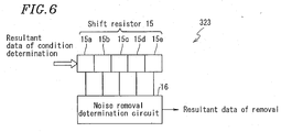
- Figure 6 is a block diagram showing a major configuration of the noise removal circuit 323 of Figure 2 .
- the noise removal circuit 323 comprises a shift resistor 15 for retaining determination results and a noise removal determination circuit 16 for determining whether or not data is noise, based on the retained five determination results.
- Figure 7 is a circuit diagram showing a major configuration of the noise removal determination circuit 323 of Figure 2 .
- the noise removal determination circuit 16 comprises AND circuits 16a to 16j and an OR circuit 16k .
- the input terminals of the AND circuit 16a are connected to the output terminals of from the third resistor unit 15c to the fifth resistor unit 15e. If all data in the resistor units 15c to 15e are "1", the AND circuit 16a outputs "1".
- the AND circuits 16b to 16h if all data in units (three units in Figure 7 ) in the shift resistor 15 connected to input terminals of the AND circuit are "1", the AND circuit outputs "1".
- the output terminals of the AND circuits 16a to 16j are connected to the respective input terminals of the OR circuit 16k .
- the OR circuit 16k outputs "1". Therefore, if three or more of five pieces of data retained in the units of the shift resistor 15 are "1", the OR circuit 16k outputs "1" as data indicating the result of noise removal. In this case, it is determined that an object satisfying extraction conditions is present, but not noise.
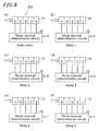
- Figure 8 is a diagram for explaining an exemplary operation of the noise removal circuit 323 of Figure 2 .
- Aportion (a) of Figure 8 indicates an initial state of the noise removal circuit 323 .
- all data in the five resistor units 15a to 15e are "0"
- the noise removal determination circuit 16 outputs "0" as data indicating the result of noise removal.
- a portion (b) of Figure 8 indicates that data is shifted by one unit, so that data "1" is read into the shift resistor 15 (state 1). In state 1, only the resistor unit 15a has data "1" among the five resistor units 15a to 15e , so that the processing result output by the noise removal determination circuit 16 is still "0".
- a portion (c) of Figure 8 indicates that another piece of data "1” is read into the shift resistor 15 (state 2).
- a portion (d) of Figure 8 indicates that another piece of data "0” is read into the shift resistor 15 (state 3).
- states 2 and 3 two resistor units have data "1” among the five resistor units 15a to 15e. In this case, the noise removal determination circuit 16 outputs "0" as data indicating the processing result.
- a portion (e) of Figure 8 indicates that another piece of data "1" is read into the shift resistor 15 (state 4).
- state 4 three or more (here three) resistor units have data "1" among the five resistor units 15a to 15e.
- the noise removal determination circuit 16 outputs data "1" as data indicating the processing result.
- a portion (f) of Figure 8 indicates that another piece of data "0" is read into the shift resistor 15 (state 5).
- state 5 three resistor units have data "1" among the five resistor units 15a to 15e.
- the noise removal determination circuit 16 still outputs data "1" as data indicating the processing result.
- the number of determination operations performed by the extraction condition determination circuit 322 is not limited to five. If the noise removal circuit 323 can determine whether or not data is a part of an object to be extracted, based on the number of resistor units having the same determination result, the number of resistor units in a shift resistor and the number of determination operations by the extraction condition determination circuit 322 are not particularly limited.
- the number of determination operations is (2n-1) (odd number: n is an interger of 1 or more) and the majority of the (2n-1) resistor units have the same determination result, it may be determined that data input to the noise removal circuit 323 is a part of an object to be extracted but not noise. If the number of determination operations is 7, the shift resistor contains at least 7 resistor units.
- the number of determination operations is 2n (even number: n is an integer of 1 or more) and the majority of the 2n resistor units have the same result, it may be determined that data input to the noise removal circuit 323 is a part of an object to be extracted but not noise.
- the number of determination operations is 6, the shift resistor contains at least 6 resistor units.
- step S6 the object inclusion relation determination in step S6 and the object inclusion relation determination circuit 324 of Figure 2 will be described in detail.
- the object inclusion relation determination circuit 234 determines whether an object which has been determined to be an object to be extracted is a part of an object which has been already extracted or a new object which has not been extracted.
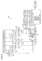
- Figure 9 is a flowchart showing an exemplary processing flow in object inclusion relation determination in step S6 of Figure 3 .
- the object information storing register 325 stores coordinate data indicating the location of the object, i.e., coordinate data indicating the coordinates on the image pickup device 22 .
- a condition matching flag indicating which condition is satisfied by an object is retained.
- the following four pieces of coordinate data are stored in the object information storing register 325 :
- the size, shape or the like of an object may be roughly determined, thereby making it possible to detect the movement and change of the object. Only coordinate data of four points is stored for an object, whereby the amount of data can be significantly reduced as compared to when entire image data is stored.
- the image processing system 1 of this embodiment incorporates the object information storing register 325 for storing coordinate data, whose size is predetermined by expecting the number of objects to be extracted. Information of extracted objects is stored in the object information storing register 325 in order of chronology of extraction from the earliest.
- a pointer for indicating the ordinal number of a resistor for storing a newly extracted object is represented by OBJ_POINT (OP).
- analog signals indicating images taken by the camera module 2 or the like contains a large amount of noise or ambiguous signals. Therefore, adjacent pixels do not necessarily provide continuous data in an object.
- first data data indicating an object to be extracted
- second data another piece of data satisfying the same conditions
- the predetermined distance is a distance criterion for determining that the first and second data are of the same object.
- the one-chip microcomputer 4 sets the distance criterion in a resistor of the object extraction LSI 3 .
- the object inclusion relation determination circuit 324 performs processing based on the distance criteria.
- the distance criterion is represented by (DX, DY).
- the first and second data are determined to be a part of the same object and the object information is updated.
- the update of the object information means that the minimum and/or maximum value of an X and/or Y coordinate are updated, and more specifically, data stored in the object information storing register 325 is updated to new minimum and/or maximum values.
- the comparison circuit 324a compares coordinate data indicating coordinates (X, Y) which have been determined to satisfy the condition 0 (e. g. , the output of the comparison circuit 324a is Yes: "1") with the coordinate data of an already detected object OBJECT_0 (e.g., an object satisfying the condition 0) using the comparison circuits 324b to 324d .
- the AND circuit 324e determines that the data indicating the coordinates (X, Y) is a part of the object OBJECT_0 (e.g., the output of the AND circuit 324e is "1").
- the determination as described above is performed for other objects OBJECT_1, OBJECT_2 (e.g., objects corresponding to the condition 1, the condition 2) ⁇ .
- the output of the AND circuit 324e is connected to the inputs of the AND circuit 324i to 324k.
- the coordinate data indicating the coordinates (X, Y) matches no objects which have been detected, the coordinate data is determined to be a part of a new object and information of the data is stored in a new resistor in the object information storing register 325 .
- the coordinate data indicating the coordinates (X, Y) is compared with the coordinate data of the already detected objects OBJECT_0, OBJECT_1, OBJECT_2, ⁇ . If the coordinate data indicating the coordinates (X, Y) matches no objects which have been detected (e.g. , all inputs of a NOR circuit 324l are "0"), it is determined that the coordinates (X, Y) are not included in any already detected objects (e.g., the output of the AND circuit 324i is "0").
- X is written into coordinate data XXMIN_OP and XXMAX_OP of an object OBJECT_OP and Y is written into YYMIN_OP and YYMAX_OP thereof, in the object information storing register 325.
- OBJ_POINT is incremented to OBJ_POINT+1 which is a pointer indicating a resistor in which a new object is to be stored.
- step S1 to step S8 the processing flow from step S1 to step S8 is repeatedly performed while one frame of image data is transferred from the camera module 2 .
- the above-described serial processing is performed every time one pixel of image data is input.
- Information is updated in real time in the object information storing register 325 . Therefore, at the time when one frame of image data has been completely transferred, information of the final result of image extraction is already stored in the object information storing register 325 .
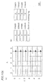
- a portion (a) of each of Figures 10A to 10E shows an exemplary manner of scanning image data.
- a portion (b) thereof indicates data states (A) to (E) of the object information storing register 325.
- condition matching flag is employed in addition to the above-described information so as to indicate that the object satisfies the conditions.
- the coordinates satisfying the conditions are located at the coordinate locations indicated by the coordinate data. If other objects are detected, a number of sets of coordinate data, which is the same as the number of the other objects, are stored in the object information storing register 324 .
- the object information storing register 324 initializes the coordinate data before the next frame of image data is output from the camera module 2 to the object extraction LSI 3 . Object information extraction is repeated from the start. Therefore, the object information stored in the object information storing register 324 is read out by the CPU 41 of the one-chip microcomputer 4 before the initialization of the object information storing register 324 .
- the CPU 41 of the one-chip microcomputer 4 detects the presence/absence of an object contained in an image, movement or change thereof, or the like, using object information extracted by the object information extraction LSI 3 .
- the image processing system is controlled. Only one frame of data can be used to recognize the size and location of an object satisfying certain conditions (hue, saturation, and lightness). By comparing the coordinate data of an object between frames, movement or change of the object can be detected.
- the object information storing register 324 stores information about an object contained in an image, i.e., object extraction conditions, coordinates having maximum X, coordinates having minimum X, coordinates having maximum Y, and coordinates having minimum Y.
- This object information is read from the object information storing register 324 into a memory (e.g. , RAM (not shown) ) or a register of the one-chip microcomputer 4 for each frame.
- a memory e.g. , RAM (not shown)
- a register of the one-chip microcomputer 4 By comparing this object information with another frame of data, movement or change of an object can be detected.
- the information amount of an extracted object is significantly smaller than preprocessed image data. Therefore, the capacity of a memory or resistor required for storing data and the processing load of the CPU 41 can be significantly reduced.
- the amount of data to be handled is: (the number of color conditions + (the number of bits for representing coordinate X + the number of bits for representing coordinate Y) ⁇ the number of coordinate points) ⁇ the number of objects.
- the difference is increased with an increase in screen size.
- the capacity of a memory or resistor for storing information about an extracted object can be significantly reduced.
- object extraction information for each frame which has been read out from the object information storing register 324 of the object information extraction circuit 32 and stored in a resistor or memory of the one-chip microcomputer 4 , can be used to compare the location (coordinates) and size of an object under certain conditions (hue, saturation, lightness) between frames. Thereby, movement of an object can be recognized.
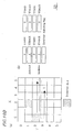
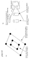
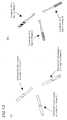
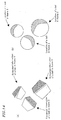
- FIGS 11 to 14 are diagrams showing an example in which the image processing system 1 of this embodiment is used to detect movement or change of an object.
- a detection example 2 of Figure 12 as shown in a portion (a) of Figure 12 , the extraction information of an object B is compared between a frame 1 and a frame 2. In this case, the center of the object B is not changed and the size of the object B is expanded. Therefore, as shown in a portion (b) of Figure 12 , it can be determined that the object B is looming toward a viewing site (camera module 1).
- a portion (a) of Figure 13 shows a cylindrical object like a bat having an upper portion and a lower portion which are painted with different colors.
- the orientation of the cylindrical object can be determined by viewing the two colors.
- the cylindrical object is a bat.
- the object information (coordinate data) of the bat is compared between a frame 1 to a frame 3.
- a portion (b) of Figure 13 by detecting changes in the orientation and location of the bat, it can be determined whether or not the bat is swung, what trajectory is drawn by the bat, how fast the bat is moved, what timing the bat is swung, or the like.
- a table tennis racket if the front and back sides of a plate-like object are painted with different colors, it can be determined which side of the racket is viewed, based on the color viewed.
- a ball is imaged.
- a ball-like object is painted with two colors.
- the movement, rotation or the like of the ball can be determined based on the orientation, distance and location of the ball, as shown in a portion (b) of Figure 14 .
- an object is painted with two colors.
- three, four, or more colors may be used.
- By adjusting the proportions of painted color areas it is possible to obtain optimum object information.
- the scope of applications of the image processing system 1 can be expanded into, for example, game apparatus or the like.
- an object in an image can be recognized. Therefore, the present invention can be applied to various input information as compared to input devices, such as a key board, a joystick, and the like.
- various object information can be extracted by the object information extraction circuit 32. Therefore, games having many changes can be achieved by adjusting an image processing program read into the one-chip microcomputer 4 and color information (e.g., information indicating hue, information indicating saturation, and information indicating lightness) of an object to be extracted, without changing the hardware configuration of the image processing system 1.
- image data from an image data output section (e.g., a camera module, etc.) is serially processed by an object information processing apparatus on a pixel-by-pixel basis. Therefore, a large-capacity memory for storing image data is not required, as is different from conventional techniques. Thus, complicated calculation and processing flows are not required for object extraction. As a result, image processing can be performed in real time without using a clock signal faster than an image transfer clock signal and the load of image processing on a CPU can be minimized.
- an image memory or a high-performance CPU for recognizing an object in an image which are conventionally required, are not necessary.
- a relatively low-performance, inexpensive CPU, processing operation circuit or the like can be used. Therefore, it is possible to significantly reduce the size and cost of an image processing system having a function of recognizing an object, a function of detecting movement or change of an object. Thereby, it is possible to achieve an image processing system capable of recognizing an object in an image and detecting movement or change of an object, which can be incorporated into toys, game apparatuses or the like for which low price is required.
Landscapes
- Engineering & Computer Science (AREA)
- Computer Vision & Pattern Recognition (AREA)
- Physics & Mathematics (AREA)
- General Physics & Mathematics (AREA)
- Theoretical Computer Science (AREA)
- Multimedia (AREA)
- Image Analysis (AREA)
- Image Processing (AREA)
- Closed-Circuit Television Systems (AREA)
- Facsimile Image Signal Circuits (AREA)
- Color Image Communication Systems (AREA)
Applications Claiming Priority (2)
| Application Number | Priority Date | Filing Date | Title |
|---|---|---|---|
| JP2002363151A JP4521747B2 (ja) | 2002-12-13 | 2002-12-13 | 物体情報処理装置、画像処理システム、ゲーム装置および画像処理方法 |
| JP2002363151 | 2002-12-13 |
Publications (2)
| Publication Number | Publication Date |
|---|---|
| EP1437686A2 true EP1437686A2 (de) | 2004-07-14 |
| EP1437686A3 EP1437686A3 (de) | 2006-01-18 |
Family
ID=32501079
Family Applications (1)
| Application Number | Title | Priority Date | Filing Date |
|---|---|---|---|
| EP03257805A Withdrawn EP1437686A3 (de) | 2002-12-13 | 2003-12-11 | Objektinformationsverarbeitungsvorrichtung, Bildverarbeitungssystem, Spielvorrichtung und Bildverarbeitungsverfahren |
Country Status (3)
| Country | Link |
|---|---|
| US (1) | US7248750B2 (de) |
| EP (1) | EP1437686A3 (de) |
| JP (1) | JP4521747B2 (de) |
Cited By (2)
| Publication number | Priority date | Publication date | Assignee | Title |
|---|---|---|---|---|
| CN102810204A (zh) * | 2012-07-03 | 2012-12-05 | 天津大学 | 基于平行四边形的单目视觉单幅图像定位方法 |
| WO2015026874A1 (en) * | 2013-08-19 | 2015-02-26 | Nant Holdings Ip, Llc | Metric based recognition, systems and methods |
Families Citing this family (11)
| Publication number | Priority date | Publication date | Assignee | Title |
|---|---|---|---|---|
| KR100607046B1 (ko) | 2004-09-09 | 2006-08-01 | 주식회사 쿼터뷰 | 체감형 게임용 화상처리 방법 및 이를 이용한 게임 방법 |
| JP4609936B2 (ja) * | 2005-03-28 | 2011-01-12 | 株式会社Kddi研究所 | オブジェクト検出方式 |
| CN100419781C (zh) * | 2005-10-05 | 2008-09-17 | 三菱电机株式会社 | 图像识别装置 |
| US20100082612A1 (en) * | 2008-09-24 | 2010-04-01 | Microsoft Corporation | Determining relevance between an image and its location |
| TWI410127B (zh) * | 2009-12-04 | 2013-09-21 | 慧榮科技股份有限公司 | 攝像裝置及攝像裝置處理影像之方法 |
| US8475050B2 (en) * | 2009-12-07 | 2013-07-02 | Honeywell International Inc. | System and method for obstacle detection using fusion of color space information |
| US9589179B2 (en) * | 2013-12-19 | 2017-03-07 | Microsoft Technology Licensing, Llc | Object detection techniques |
| US9805662B2 (en) * | 2015-03-23 | 2017-10-31 | Intel Corporation | Content adaptive backlight power saving technology |
| CN104820997B (zh) * | 2015-05-14 | 2016-12-21 | 北京理工大学 | 一种基于分块稀疏表达与hsv特征融合的目标跟踪方法 |
| US11030775B2 (en) * | 2016-03-17 | 2021-06-08 | Flir Systems, Inc. | Minimal user input video analytics systems and methods |
| CN112597840B (zh) * | 2020-12-14 | 2024-07-12 | 深圳集智数字科技有限公司 | 一种图像识别方法、装置及设备 |
Family Cites Families (21)
| Publication number | Priority date | Publication date | Assignee | Title |
|---|---|---|---|---|
| JPS59132075A (ja) | 1983-01-18 | 1984-07-30 | Seiko Instr & Electronics Ltd | 画像処理装置 |
| JPS62264090A (ja) * | 1986-05-12 | 1987-11-17 | ソニー株式会社 | マルチスキヤンモニタ用入力インタ−フエ−ス回路 |
| JPS6388684A (ja) | 1986-10-01 | 1988-04-19 | Daido Steel Co Ltd | 物体認識方法 |
| US5717440A (en) * | 1986-10-06 | 1998-02-10 | Hitachi, Ltd. | Graphic processing having apparatus for outputting FIFO vacant information |
| US5249264A (en) * | 1988-11-14 | 1993-09-28 | International Business Machines Corporation | Image display method and apparatus |
| US5235650A (en) * | 1989-02-02 | 1993-08-10 | Samsung Electronics Co. Ltd. | Pattern classifier for character recognition |
| JPH06266841A (ja) | 1993-03-12 | 1994-09-22 | Matsushita Electric Ind Co Ltd | 物体認識装置 |
| TW348239B (en) * | 1996-06-28 | 1998-12-21 | Cirrus Logic Inc | Embedding a transparency enable bit as part of a resizing bit block transfer operation |
| US6144374A (en) * | 1997-05-15 | 2000-11-07 | Orion Electric Co., Ltd. | Apparatus for driving a flat panel display |
| US6263088B1 (en) | 1997-06-19 | 2001-07-17 | Ncr Corporation | System and method for tracking movement of objects in a scene |
| US6380946B1 (en) * | 1999-02-09 | 2002-04-30 | Intel Corporation | Enhancing hardware clipping for bit-packed fonts |
| US6417861B1 (en) * | 1999-02-17 | 2002-07-09 | Sun Microsystems, Inc. | Graphics system with programmable sample positions |
| JP3921015B2 (ja) * | 1999-09-24 | 2007-05-30 | 富士通株式会社 | 画像解析装置及び方法並びにプログラム記録媒体 |
| JP3603737B2 (ja) * | 2000-03-30 | 2004-12-22 | 日本電気株式会社 | 移動体追尾方法及びその装置 |
| US6967664B1 (en) * | 2000-04-20 | 2005-11-22 | Ati International Srl | Method and apparatus for primitive processing in a graphics system |
| DE10024374B4 (de) * | 2000-05-17 | 2004-05-06 | Micronas Munich Gmbh | Verfahren und Vorrichtung zum Messen des in einem Bild enthaltenen Rauschens |
| KR100450793B1 (ko) * | 2001-01-20 | 2004-10-01 | 삼성전자주식회사 | 영역 분할된 영상의 영역 특징치 정합에 기초한객체추출장치 및 그 방법 |
| JP3753954B2 (ja) * | 2001-06-11 | 2006-03-08 | 株式会社メガチップス | 画像処理装置および画像処理システム |
| US6778180B2 (en) * | 2001-09-28 | 2004-08-17 | The United States Of America As Represented By The Administrator Of The National Aeronautics And Space Administration | Video image tracking engine |
| US6693643B1 (en) * | 2001-12-31 | 2004-02-17 | Apple Computer, Inc. | Method and apparatus for color space conversion |
| KR100547812B1 (ko) * | 2002-06-24 | 2006-01-31 | 삼성전자주식회사 | 컬러 참조테이블을 사용하여 화소데이터의 컬러모델을변환하는 장치 및 방법 |
-
2002
- 2002-12-13 JP JP2002363151A patent/JP4521747B2/ja not_active Expired - Fee Related
-
2003
- 2003-12-05 US US10/727,609 patent/US7248750B2/en not_active Expired - Fee Related
- 2003-12-11 EP EP03257805A patent/EP1437686A3/de not_active Withdrawn
Cited By (7)
| Publication number | Priority date | Publication date | Assignee | Title |
|---|---|---|---|---|
| CN102810204A (zh) * | 2012-07-03 | 2012-12-05 | 天津大学 | 基于平行四边形的单目视觉单幅图像定位方法 |
| WO2015026874A1 (en) * | 2013-08-19 | 2015-02-26 | Nant Holdings Ip, Llc | Metric based recognition, systems and methods |
| US9659033B2 (en) | 2013-08-19 | 2017-05-23 | Nant Holdings Ip, Llc | Metric based recognition, systems and methods |
| US9824292B2 (en) | 2013-08-19 | 2017-11-21 | Nant Holdings Ip, Llc | Metric-based recognition, systems and methods |
| US10121092B2 (en) | 2013-08-19 | 2018-11-06 | Nant Holdings Ip, Llc | Metric-based recognition, systems and methods |
| US10346712B2 (en) | 2013-08-19 | 2019-07-09 | Nant Holdings Ip, Llc | Metric-based recognition, systems and methods |
| US11062169B2 (en) | 2013-08-19 | 2021-07-13 | Nant Holdings Ip, Llc | Metric-based recognition, systems and methods |
Also Published As
| Publication number | Publication date |
|---|---|
| EP1437686A3 (de) | 2006-01-18 |
| JP2004192582A (ja) | 2004-07-08 |
| JP4521747B2 (ja) | 2010-08-11 |
| US7248750B2 (en) | 2007-07-24 |
| US20040113917A1 (en) | 2004-06-17 |
Similar Documents
| Publication | Publication Date | Title |
|---|---|---|
| EP1437686A2 (de) | Objektinformationsverarbeitungsvorrichtung, Bildverarbeitungssystem, Spielvorrichtung und Bildverarbeitungsverfahren | |
| JP2020509506A (ja) | カメラ姿勢情報の決定方法、装置、デバイス及び記憶媒体 | |
| Ghaffari et al. | Analysis and comparison of FPGA-based histogram of oriented gradients implementations | |
| JP3434979B2 (ja) | 局所領域画像追跡装置 | |
| US10621446B2 (en) | Handling perspective magnification in optical flow processing | |
| JP2022511427A (ja) | 画像特徴点の動き情報の決定方法、タスク実行方法およびデバイス | |
| EP1309009A2 (de) | CMOS Bildsensor mit Bildmustererkennung auf einem Chip | |
| JP2010136413A (ja) | 高速視覚センサ装置 | |
| EP1361541A1 (de) | Verfahren und Vorrichtung zur globalen Bewegungsschätzung innerhalb einer Bildsequenz, z.B. für optische Mäuse | |
| CN100487522C (zh) | 模糊校正方法及摄像装置 | |
| JP7583526B2 (ja) | 画像処理装置およびその制御方法ならびにプログラム | |
| KR20010004946A (ko) | 고속 컨벌루션 처리 방법 및 그 장치 | |
| JP4763219B2 (ja) | 運動する物体に付された光学信号マークの重心を写真測量により決定する方法及び装置 | |
| Dudek | A flexible global readout architecture for an analogue SIMD vision chip | |
| JP4334672B2 (ja) | 高速視覚センサ装置 | |
| US20130223697A1 (en) | Face detection-processing circuit and image pickup device including the same | |
| JP3653945B2 (ja) | 色抽出装置及び色抽出方法 | |
| US8305460B2 (en) | Detection device and image capture system using the same | |
| JP2020098114A (ja) | 自己位置推定装置、自己位置推定方法及びプログラム | |
| CN100416476C (zh) | 手持式指向装置以及估计一位移量的方法 | |
| JP2865168B1 (ja) | 動作データ作成システム | |
| Zhang et al. | RAW Images-Based Motion-Assisted Object Detection Accelerator Using Deformable Parts Models Features on 1080p Videos | |
| CN113408710A (zh) | 一种深度卷积神经网络加速方法、模块、系统及存储介质 | |
| CN100371861C (zh) | 一种基于计算机图像和纯色物体的互动输入控制方法 | |
| KR100652632B1 (ko) | 카메라를 구비한 이동 통신 단말기의 3d 게임 방향 전환장치 및 그 방법 |
Legal Events
| Date | Code | Title | Description |
|---|---|---|---|
| PUAI | Public reference made under article 153(3) epc to a published international application that has entered the european phase |
Free format text: ORIGINAL CODE: 0009012 |
|
| AK | Designated contracting states |
Kind code of ref document: A2 Designated state(s): AT BE BG CH CY CZ DE DK EE ES FI FR GB GR HU IE IT LI LU MC NL PT RO SE SI SK TR |
|
| AX | Request for extension of the european patent |
Extension state: AL LT LV MK |
|
| RIN1 | Information on inventor provided before grant (corrected) |
Inventor name: MATSUMOTO, KAZUYOSHI |
|
| PUAL | Search report despatched |
Free format text: ORIGINAL CODE: 0009013 |
|
| AK | Designated contracting states |
Kind code of ref document: A3 Designated state(s): AT BE BG CH CY CZ DE DK EE ES FI FR GB GR HU IE IT LI LU MC NL PT RO SE SI SK TR |
|
| AX | Request for extension of the european patent |
Extension state: AL LT LV MK |
|
| RIC1 | Information provided on ipc code assigned before grant |
Ipc: G06T 7/00 20060101ALI20051130BHEP Ipc: G06T 7/20 20060101ALI20051130BHEP Ipc: G06T 5/00 20060101AFI20051130BHEP |
|
| 17P | Request for examination filed |
Effective date: 20060712 |
|
| 17Q | First examination report despatched |
Effective date: 20060822 |
|
| AKX | Designation fees paid |
Designated state(s): DE FR GB |
|
| GRAP | Despatch of communication of intention to grant a patent |
Free format text: ORIGINAL CODE: EPIDOSNIGR1 |
|
| STAA | Information on the status of an ep patent application or granted ep patent |
Free format text: STATUS: THE APPLICATION IS DEEMED TO BE WITHDRAWN |
|
| 18D | Application deemed to be withdrawn |
Effective date: 20091118 |