EP1437555A2 - Multi-type air conditioner - Google Patents
Multi-type air conditioner Download PDFInfo
- Publication number
- EP1437555A2 EP1437555A2 EP03023594A EP03023594A EP1437555A2 EP 1437555 A2 EP1437555 A2 EP 1437555A2 EP 03023594 A EP03023594 A EP 03023594A EP 03023594 A EP03023594 A EP 03023594A EP 1437555 A2 EP1437555 A2 EP 1437555A2
- Authority
- EP
- European Patent Office
- Prior art keywords
- refrigerant
- heat exchanger
- pipeline
- indoor
- port
- Prior art date
- Legal status (The legal status is an assumption and is not a legal conclusion. Google has not performed a legal analysis and makes no representation as to the accuracy of the status listed.)
- Granted
Links
Images


Classifications
-
- F—MECHANICAL ENGINEERING; LIGHTING; HEATING; WEAPONS; BLASTING
- F25—REFRIGERATION OR COOLING; COMBINED HEATING AND REFRIGERATION SYSTEMS; HEAT PUMP SYSTEMS; MANUFACTURE OR STORAGE OF ICE; LIQUEFACTION SOLIDIFICATION OF GASES
- F25B—REFRIGERATION MACHINES, PLANTS OR SYSTEMS; COMBINED HEATING AND REFRIGERATION SYSTEMS; HEAT PUMP SYSTEMS
- F25B13/00—Compression machines, plants or systems, with reversible cycle
-
- F—MECHANICAL ENGINEERING; LIGHTING; HEATING; WEAPONS; BLASTING
- F25—REFRIGERATION OR COOLING; COMBINED HEATING AND REFRIGERATION SYSTEMS; HEAT PUMP SYSTEMS; MANUFACTURE OR STORAGE OF ICE; LIQUEFACTION SOLIDIFICATION OF GASES
- F25B—REFRIGERATION MACHINES, PLANTS OR SYSTEMS; COMBINED HEATING AND REFRIGERATION SYSTEMS; HEAT PUMP SYSTEMS
- F25B40/00—Subcoolers, desuperheaters or superheaters
- F25B40/02—Subcoolers
-
- F—MECHANICAL ENGINEERING; LIGHTING; HEATING; WEAPONS; BLASTING
- F25—REFRIGERATION OR COOLING; COMBINED HEATING AND REFRIGERATION SYSTEMS; HEAT PUMP SYSTEMS; MANUFACTURE OR STORAGE OF ICE; LIQUEFACTION SOLIDIFICATION OF GASES
- F25B—REFRIGERATION MACHINES, PLANTS OR SYSTEMS; COMBINED HEATING AND REFRIGERATION SYSTEMS; HEAT PUMP SYSTEMS
- F25B2313/00—Compression machines, plants or systems with reversible cycle not otherwise provided for
- F25B2313/007—Compression machines, plants or systems with reversible cycle not otherwise provided for three pipes connecting the outdoor side to the indoor side with multiple indoor units
-
- F—MECHANICAL ENGINEERING; LIGHTING; HEATING; WEAPONS; BLASTING
- F25—REFRIGERATION OR COOLING; COMBINED HEATING AND REFRIGERATION SYSTEMS; HEAT PUMP SYSTEMS; MANUFACTURE OR STORAGE OF ICE; LIQUEFACTION SOLIDIFICATION OF GASES
- F25B—REFRIGERATION MACHINES, PLANTS OR SYSTEMS; COMBINED HEATING AND REFRIGERATION SYSTEMS; HEAT PUMP SYSTEMS
- F25B2313/00—Compression machines, plants or systems with reversible cycle not otherwise provided for
- F25B2313/023—Compression machines, plants or systems with reversible cycle not otherwise provided for using multiple indoor units
- F25B2313/0231—Compression machines, plants or systems with reversible cycle not otherwise provided for using multiple indoor units with simultaneous cooling and heating
-
- F—MECHANICAL ENGINEERING; LIGHTING; HEATING; WEAPONS; BLASTING
- F25—REFRIGERATION OR COOLING; COMBINED HEATING AND REFRIGERATION SYSTEMS; HEAT PUMP SYSTEMS; MANUFACTURE OR STORAGE OF ICE; LIQUEFACTION SOLIDIFICATION OF GASES
- F25B—REFRIGERATION MACHINES, PLANTS OR SYSTEMS; COMBINED HEATING AND REFRIGERATION SYSTEMS; HEAT PUMP SYSTEMS
- F25B2313/00—Compression machines, plants or systems with reversible cycle not otherwise provided for
- F25B2313/023—Compression machines, plants or systems with reversible cycle not otherwise provided for using multiple indoor units
- F25B2313/0233—Compression machines, plants or systems with reversible cycle not otherwise provided for using multiple indoor units in parallel arrangements
- F25B2313/02331—Compression machines, plants or systems with reversible cycle not otherwise provided for using multiple indoor units in parallel arrangements during cooling
-
- F—MECHANICAL ENGINEERING; LIGHTING; HEATING; WEAPONS; BLASTING
- F25—REFRIGERATION OR COOLING; COMBINED HEATING AND REFRIGERATION SYSTEMS; HEAT PUMP SYSTEMS; MANUFACTURE OR STORAGE OF ICE; LIQUEFACTION SOLIDIFICATION OF GASES
- F25B—REFRIGERATION MACHINES, PLANTS OR SYSTEMS; COMBINED HEATING AND REFRIGERATION SYSTEMS; HEAT PUMP SYSTEMS
- F25B2313/00—Compression machines, plants or systems with reversible cycle not otherwise provided for
- F25B2313/023—Compression machines, plants or systems with reversible cycle not otherwise provided for using multiple indoor units
- F25B2313/0233—Compression machines, plants or systems with reversible cycle not otherwise provided for using multiple indoor units in parallel arrangements
- F25B2313/02334—Compression machines, plants or systems with reversible cycle not otherwise provided for using multiple indoor units in parallel arrangements during heating
-
- F—MECHANICAL ENGINEERING; LIGHTING; HEATING; WEAPONS; BLASTING
- F25—REFRIGERATION OR COOLING; COMBINED HEATING AND REFRIGERATION SYSTEMS; HEAT PUMP SYSTEMS; MANUFACTURE OR STORAGE OF ICE; LIQUEFACTION SOLIDIFICATION OF GASES
- F25B—REFRIGERATION MACHINES, PLANTS OR SYSTEMS; COMBINED HEATING AND REFRIGERATION SYSTEMS; HEAT PUMP SYSTEMS
- F25B2500/00—Problems to be solved
- F25B2500/24—Low amount of refrigerant in the system
Definitions
- the present invention relates to multi-type air conditioners, and more particularly, to a multi-type air conditioner which can cool or heat a plurality of rooms, individually.
- the air conditioner is an appliance for cooling or heating spaces, such as living spaces, restaurants, and offices. At present, for effective cooling or heating of a space partitioned into many rooms, it is a trend that there has been ceaseless development of multi-type air conditioner.
- the multi-type air conditioner is in general provided with one outdoor unit and a plurality of indoor units each connected to the outdoor unit and installed in a room, for cooling or heating the room while operating in one of cooling or heating mode.
- the multi-type air conditioner is operative only in one mode of cooling or heating uniformly even if some of the many rooms within the partitioned space require heating, and rest of the rooms require cooling, the multi-type air conditioner has a limit in that the requirement can not be met, properly.
- the requirement demands development of multi-type air conditioner of concurrent cooling/heating type, for making air conditioning of rooms individually, i.e., the indoor unit installed in a room requiring heating is operable in a heating mode, and, at the same time, the indoor unit installed in a room requiring cooling is operable in a cooling mode.
- the present invention is directed to a multi-type air conditioner that substantially obviates one or more of the problems due to limitations and disadvantages of the related art.
- An object of the present invention is to provide a multi-type air conditioner, which can heat or cool rooms individually proper to room requirements at the same time, and in which introduction of two phased refrigerant into an expansion device of an indoor unit is prevented, for preventing deterioration of cooling performance and occurrence of noise.
- the multi-type air conditioner includes an outdoor unit having a compressor, an outdoor heat exchanger, a flow path control valve for controlling a flow path of the refrigerant from the compressor, an outdoor expansion device for expanding liquid refrigerant introduced thereto in a condensed state via indoor units and providing to the outdoor heat exchanger when the room is heated, and an outdoor unit piping system, a plurality of indoor units each having an indoor expansion device, an indoor heat exchanger, and an indoor piping system, a distributor for selectively distributing the refrigerant from the outdoor unit to the indoor units and returning to the outdoor unit again proper to respective operation modes, and means for super cooling the refrigerant condensed at the outdoor heat exchanger or the indoor heat exchangers and flowed to the indoor expansion devices or to the outdoor expansion device.
- the means includes a super cooling heat exchanger designed so as to heat exchange with a part of a pipeline between the outdoor expansion device and the indoor expansion devices in a pipeline the outdoor heat exchanger, the outdoor expansion device, the indoor expansion devices and the indoor heat exchangers connected in series.
- the super cooling heat exchanger uses a part of refrigerant flowing through the refrigerant pipe for super cooling rest of refrigerant passing through a part where the rest of refrigerant heat exchanges with the super cooling heat exchanger.
- the means further includes a first guide pipe connected between the refrigerant pipeline and one end of the super cooling heat exchanger for guiding a portion of refrigerant flowing through the liquid refrigerant pipeline after having passed through the indoor heat exchanger, a super cooling expansion device mounted on the first guide pipe for expanding the refrigerant flowing through the first guide pipe, and a second guide pipe connected between the inlet of the compressor and the other end of the super cooling heat exchanger for guiding the refrigerant passed through the super cooling heat exchanger to the compressor.
- the means further includes a supplementary super cooling heat exchanger mounted on a refrigerant pipeline between the super cooling heat exchanger and the outdoor expansion device.
- the means further includes a first supplementary guide pipe connected between the refrigerant pipeline and one end of the supplementary super cooling heat exchanger, a supplementary super cooling expansion device on the first supplementary guide pipe, and a second supplementary guide pipe connected between the inlet of the compressor and the other end of the supplementary super cooling heat exchanger.
- the super cooling heat exchanger surrounds an outside surface of the refrigerant pipeline.
- the super cooling heat exchanger passes through an inside of the refrigerant pipeline.
- the super cooling heat exchanger includes many bends inside of the refrigerant pipeline for enlarging an area of heat exchange with the refrigerant flowing through the refrigerant pipeline.
- the flow path control valve includes a first port in communication with the compressor, a second port in communication with the outdoor heat exchanger, a third port in communication with an inlet of the compressor, and a fourth port connected to a closed pipe piece or blanked.
- the outdoor unit piping system includes a first pipeline connected between an outlet of the compressor and the first port, a second pipeline connected between the second port and the first port of the outdoor unit, the second pipeline having the outdoor heat exchanger mounted in the middle thereof, a third pipeline connected between the first pipeline and the second pipeline of the outdoor unit, and a fourth pipeline connected between the third port and the inlet of the compressor, having the third port of the outdoor unit connected to the middle thereof.
- the first port of the outdoor unit is connected to the first port of the distributor
- the second port of the outdoor unit is connected to the second port of the distributor
- the third port of the outdoor unit is connected to the third port of the distributor.
- the distributor includes a distributor piping system for guiding refrigerant from the outdoor unit to the indoor units, and vice versa, and a valve bank mounted on the distributor piping system for controlling flow of refrigerant flowing through the distributor piping system proper to respective operation modes.
- the distributor piping system includes a liquid refrigerant pipeline having a first port of the distributor, a plurality of liquid refrigerant branch pipelines branched from the liquid refrigerant pipeline and connected to the indoor unit expansion devices in the indoor units respectively, a gas refrigerant pipeline having a second port of the distributor, a plurality of first gas refrigerant branch pipelines branched from the gas refrigerant pipeline and connected to the indoor heat exchangers of the indoor units respectively, a plurality of second gas refrigerant branch pipelines branched from intermediate points of the first gas refrigerant branch pipelines respectively, a return pipeline having all the second gas refrigerant pipelines connected thereto, and a third port of the distributor.
- the super cooling heat exchanger is mounted at a part where the liquid refrigerant pipeline and the liquid refrigerant branch pipeline join. It is preferable that the first guide pipe is branched from the liquid refrigerant pipeline and connected to the super cooling heat exchanger, and the second guide pipe is connected to the return pipeline.
- a multi-type air conditioner including an outdoor unit having a compressor, and an outdoor heat exchanger, a plurality of indoor units each connected to the outdoor unit directly having an indoor expansion device, and an indoor heat exchanger, and a super cooling heat exchanger mounted on a refrigerant pipeline between the outdoor heat exchanger and the indoor expansion device in the refrigerant pipeline connecting the outdoor heat exchanger, the indoor expansion devices, and the indoor heat exchangers in series, for super cooling the refrigerant.
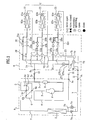
- the air conditioner includes an outdoor unit 'A', a distributor 'B', and a plurality of indoor units 'C'; 'C1', 'C2', and 'C3'.
- the outdoor unit 'A' has a compressor 1, an outdoor heat exchanger 2, a flow path control valve 6, and an outdoor unit piping system
- the distributor 'B' has a distribution piping system 20, and a valve bank 30.
- Each of the indoor units 'C'; has an indoor heat exchanger 62 and indoor unit expansion device 61.
- the air conditioner of the present invention includes super cooling means 70 additionally for enhancing an air conditioning efficiency and reducing noise and occurrence of out of order of the air conditioner.
- the air conditioner has a system in which rooms the indoor units 'C'; 'C1', 'C2', and 'C3' are installed therein respectively are cooled or heated individually according to different operation modes of a first operation mode of cooling all rooms, a second operation mode of heating all rooms, a third operation mode of cooling a major number of the rooms and heating a minor number of rooms, and a fourth operation mode of heating a major number of the rooms and cooling a minor number of rooms, detail of one preferred embodiment of which will be described with reference to FIG. 1.
- 22 represents 22a, 22b, and 22c
- 24 represents 24a, 24b, and 24c
- 25 represents 25a, 25b, and 25c
- 31 represents 31a, 31b, and 31c
- 32 represents 32a, 32b, and 32c
- 61 represents 61a, 61b, and 61c
- 62 represents 62a, 62b, and 62c
- C represents C1, C2, and C3.
- a number of the indoor units 'C' and numbers of elements related thereto are varied with a number of rooms, and for convenience of description, the specification describes assuming a case when there are three rooms, i.e., a number of the indoor units are three.
- the outdoor unit 'A' of the air conditioner of the present invention will be described.
- a first pipeline 3 connected to an outlet of the compressor 1.
- the first pipeline 3 is connected to the flow path control valve 6, which controls a flow path of gas refrigerant from the compressor 1 according to respective operation modes.
- the flow path control valve has four ports, of which first port 6a is connected to the first pipeline 3.
- the second port 6b of the flow path control valve 6 is connected to a second pipeline 7.
- the second pipeline 7 has one end connected to the second port 6b of the flow path control valve 6, and the other end connected to a first port A1 of the outdoor unit 'A' as shown in FIG. 1.
- the third port 6c of the flow path control valve 6 is connected to a fourth pipeline 5.
- the fourth pipeline 5 has one end connected to the third port 6c, and the other end connected to an inlet of the compressor 1.
- An intermediate point of the fourth pipeline 5 is in communication with the third port A3 of the outdoor unit 'A'.
- an intermediate point of the fourth pipeline 5 in more detail, at a point between the inlet of the compressor 1 and the third port A3 of the outdoor unit 'A', there is an accumulator 9.
- the fourth port 6d of the flow path control valve 6 is connected to a pipe piece 6e with one blanked end. Or, the fourth port 6d may not be connected to the pipe piece, but the fourth port 6d itself may be closed.
- the flow path control valve 6 makes the first port 6a and the second port 6b in communication and, at the same time with this, makes the third port 6c and the fourth port 6d in communication when the multi-type air conditioner is in operation in the first or third operation mode. Also, the flow path control valve 6 makes the first port 6a and the fourth port 6d in communication and, at the same time with this, makes the second port 6b and the third port 6c in communication when the multi-type air conditioner is in operation in the second or fourth operation mode.
- the refrigerant flow controlled thus by the flow path control valve 6 will be described in detail, later.
- a third pipeline 4 one end of which is connected to the middle of the first pipeline 3.
- the other end of the third pipeline 4 is connected to a second port A2 of the outdoor unit 'A'.
- a check valve 7a on an intermediate point of the second pipeline 7, in more detail, a point between the outdoor heat exchanger 2 and the first port A1 of the outdoor unit 'A'. It is preferable that the check valve 7a is mounted adjacent to the outdoor heat exchanger 2.
- a parallel pipe piece 7b having two ends connected to an inlet and an outlet of the check valve 7a is provided, and the outdoor expansion device 7c is mounted on the parallel pipe piece 7b.
- the check valve 7a passes refrigerant flowing from the outdoor heat exchanger 2 to the first port A1 of the outdoor unit 'A', and blocks refrigerant flowing from the first port A1 of the outdoor unit 'A' to the outdoor heat exchanger 2. Therefore, the refrigerant flowing from the first port A1 of the outdoor unit 'A' to the outdoor heat exchanger 2 bypasses the check valve 7a to pass through the parallel pipe 7b and the outdoor unit expansion device 7c, and therefrom flows into the outdoor heat exchanger 2.
- the outdoor expansion device 7c can open a flow passage, a function identical to above description can be made even if no check valve 7a is provided. That is, if the outdoor expansion device 7c opens a flow passage, when the refrigerant flows from the outdoor heat exchanger 2 toward the distributor 'B', and, if the outdoor expansion device 7c expands the refrigerant, when the refrigerant flows from the distributor 'B' toward the outdoor heat exchanger 2, the same function as the embodiment in which the check valve 7a is provided can be carried out.
- the outdoor unit 'A' having the foregoing system is connected to the distributor 'B' with a plurality of connection pipelines.
- a first connection pipeline 11 connects the first port A1 of the outdoor unit 'A' to the first port B1 of the distributor 'B'
- a second connection pipeline 12 connects a second port A2 of the outdoor unit 'A' and a second port B2 of the distributor 'B'
- a third connection pipeline 13 connects a third port A3 of the outdoor unit 'A' and a third port B3 of the distributor 'B'.
- the outdoor unit 'A' and the distributor 'B' are connected with three pipelines.
- the distributor 'B' guides the refrigerant from the outdoor unit 'A' to selected indoor unit 'C' exactly.
- the plurality of pipelines connecting the distributor 'B' to the plurality of indoor unit 'C' are simplified, for easy piping work and improving an outer appearance.
- the distributor 'B' of the air conditioner of the present invention designed taken the foregoing matters into account includes the distributor piping system 20, and the valve bank 30.
- the distributor piping system 20 guides refrigerant flow from the outdoor unit 'A' to the indoor units 'C', and vice versa.
- the distributor piping system 20 includes a liquid refrigerant pipeline 21, a plurality of liquid refrigerant branch pipelines 22, a gas refrigerant pipeline 23, and a plurality of first refrigerant branch pipelines 24, a plurality of second branch pipelines 25, and a return pipeline 26.
- the liquid refrigerant pipeline 21 provides a first port B1 of the distributor 'B' for connection to the first connection pipeline 11.
- the plurality of liquid refrigerant branch pipelines 22 are branched from the liquid refrigerant pipeline 21 and connected to the indoor unit expansion devices 61 in the indoor units 'C', respectively.
- the gas refrigerant pipeline 23 provides a second port B2 of the distributor 'B' for connection to the second connection pipeline 12.
- the plurality of first gas refrigerant branch pipelines 24 are branched from the gas refrigerant pipeline 23 and connected to the indoor heat exchangers 62 of the indoor units C, respectively.
- the plurality of second gas refrigerant branch pipelines 25 are branched from intermediate points of the first gas refrigerant branch pipelines 24 respectively. As shown in FIG. 1, the return pipeline 26 has all the second gas refrigerant pipelines 25 connected thereto. The return pipe 26 has a third port B3 of the distributor 'B'.
- the valve bank 30 in the distributor 'B' controls refrigerant flow in the distributor piping system, such that gas or liquid refrigerant is introduced into the indoor units in the rooms selectively, and returns from the indoor units 'C' to the outdoor unit 'A'.
- the valve bank 30 includes a plurality of open/close valves 31a, 31b, 31c, 32a, 32b, and 32c mounted on the first gas refrigerant branch pipelines 24 and the second gas refrigerant branch pipelines 25, respectively.
- the valves 31 and 32 open or close the first gas refrigerant branch pipelines 24 and the second gas refrigerant branch pipelines 25 respectively for controlling refrigerant flow paths according to the operation modes.
- detailed control of the valve bank 30 will be described in a description of operation of the air conditioner of the present invention for each operation mode.
- the distributor 'B' of the multi-type air conditioner of the present invention may also include means 27 for preventing high pressure refrigerant staying in the second connection pipeline 12 from being liquefied when the multi-type air conditioner is in the first operation mode. Because there may be shortage of refrigerant for cooling or heating if the high pressure refrigerant is stagnant and liquefied in the second connection pipeline 12, the means 27 is provided to the distributor 'B' for vaporizing liquid refrigerant and preventing liquefaction of the high pressure refrigerant in the second connection pipeline 12 to prevent shortage of refrigerant in the air conditioner at the end.
- the means 27 includes a bypass pipe 27a connected between the return pipeline 26 and the gas refrigerant pipeline 23, and a distributor expansion device 27b on the bypass pipeline 27a. The operation of the means 27 will be described in detail, later.
- the indoor unit 'C' installed in each room, includes the indoor heat exchanger 62, indoor unit expansion device 61, and room fan (not shown).
- the indoor heat exchanger 62 is connected to respective first gas refrigerant branch pipeline 24 in the distributor 'B', and the indoor unit expansion device 61 is connected to respective liquid refrigerant branch pipeline 22 in the distributor 'B'.
- the indoor heat exchangers 62 and the indoor unit expansion devices 61 are connected with refrigerant pipe.
- the room fan blows air to respective indoor heat exchanger 62.
- Super cooling means provided to the multi-type air conditioner of the present invention will be described. Before starting description of a structure and mounting location of the super cooling means, necessity for the super cooling means will be described, briefly.
- the outdoor unit 'A' is installed on an outside of a building, such as a roof top of a building, while the indoor units C are installed at respective rooms in the building.
- the distributor 'B' is installed in the middle of the outdoor unit 'A' and the indoor units C, for an example, a space in the building, or an inside of ceiling.
- the multi-type air conditioner of the present invention includes the super cooling means 70, additionally.
- the super cooling means 70 is mounted on the distributor 'B', for super cooling the refrigerant condensed at the outdoor heat exchanger 2 or the indoor heat exchangers 62 and flows toward the indoor expansion devices 61 or the outdoor expansion device 7c.
- the super cooling means 70 includes a super cooling heat exchanger 71.
- the super cooling heat exchanger 71 is designed so as to heat exchange with a part of a pipeline between the outdoor expansion device 7c and the indoor expansion devices 61 in a pipeline the outdoor heat exchanger 2, the outdoor expansion device 7c, the indoor expansion devices 61 and the indoor heat exchangers connected in series.
- the super cooling heat exchanger 71 is mounted on a part the liquid refrigerant branch pipeline 22 is branched from the liquid refrigerant pipeline 21.
- the super cooling heat exchanger 71 mounted thus cools down the refrigerant passing through the super cooling heat exchanger 71, resulting to super cool the refrigerant.
- a variety of method can be employed for cooling the refrigerant passing through the part the super cooling heat exchanger 71 is mounted thereon. That is, cold air may be blown toward the super cooling heat exchanger 71, or cooling fluid, such as cooling water, may be supplied thereto, for cooling the refrigerant passing through the super cooling heat exchanger 71.
- the present invention suggests not employment of separate cooling fluid, but use of a portion of the refrigerant flowing in the refrigerant pipeline, i.e., the liquid refrigerant pipeline 21 for cooling the refrigerant passing through the super cooling heat exchanger 71.
- the super cooling heat exchanger 71 includes a first guide pipe 72 for guiding a portion of refrigerant flowing through the liquid refrigerant pipeline 21 to the super cooling heat exchanger 71, a super cooling expansion device 73 for expanding the refrigerant flowing through the first guide pipe 72, and a second guide pipe 74 for guiding the refrigerant passed through the super cooling heat exchanger 71 to the inlet of the compressor 1.
- the liquid refrigerant pipeline 21 has one end connected to a point where the first port B1 of the distributor 'B' and the liquid branch pipeline 22 are branched, and the other end connected to one end of the super cooling heat exchanger 71.
- the super cooling expansion device 73 is mounted on the first guide pipe 72. As shown in FIG.
- the second guide pipe 74 has one end connected to the other end of the super cooling expansion device 73, and the other end connected to the return pipeline 26.
- the refrigerant passed through the super cooling expansion device 73 is introduced into the inlet of the compressor 1 via the return pipeline 26 and the fourth pipeline 5.
- the second guide pipe 74 may be connected to the fourth pipeline 5, directly.
- the super cooling heat exchanger 71 may be positioned inside of the liquid refrigerant pipeline 21. In this instance, as shown in FIGS. 4A and 4B, it is preferable that the super cooling heat exchanger 71 is bent many times in the liquid refrigerant pipeline 21 for enlarging a heat exchange area with the refrigerant flowing in the liquid refrigerant pipeline 21 and the liquid refrigerant branch pipelines 22.
- the refrigerant flowing through the liquid refrigerant pipeline 21 becomes to contact with the super cooling heat exchanger 71 directly if the super cooling heat exchanger 71 has above form, the refrigerant flowing through the liquid refrigerant pipeline 21 becomes to heat exchange with the refrigerant flowing through the super cooling heat exchanger 71, effectively.
- FIGS. 4A and 4B illustrate an embodiment in which the liquid refrigerant pipeline 21 surrounds the super cooling heat exchanger 71, opposite to this, the liquid refrigerant pipeline 21 may pass through an inside of the super cooling heat exchanger 71.
- this embodiment can be known to persons in this field of art without any further description.
- the super cooling means 80 includes a super cooling heat exchanger 81, a first guide pipe 82, a super cooling expansion device 83, and a second guide pipe 84. Description of a structure and connection of the super cooling means 80, similar to the super cooling means 70 described before, will be omitted. However, as shown in FIG. 6, the super cooling heat exchanger 81 is mounted between the first port B1 of the distributor 'B' and the super cooling heat exchanger 71.
- the super cooling heat exchanger 71 is operated in all operation modes.
- the super cooling heat exchanger 81 is operated only in the first operation mode for prevention of drop of an air conditioning performance.
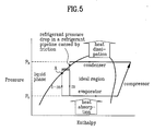
- FIG. 5 illustrates a P-h diagram showing a super cooling principle of the super cooling means in FIG. 1.
- the outdoor heat exchanger 2 serves as a condenser
- the indoor heat exchanger 62 serves as an evaporator.
- the refrigerant is compressed to a high pressure at the compressor 1, and transferred to the outdoor heat exchanger 2 in FIG. 1 which serves as a condenser, where the refrigerant discharges heat at a fixed pressure, and condensed into liquid refrigerant.
- the refrigerant liquefied at the outdoor heat exchanger 2 is transferred to the distributor 'B' via the second pipeline 7 in FIG. 1.
- the refrigerant pipeline connected between the outdoor heat exchanger 'A' and the distributor 'B' i.e., the first connection pipeline 11 is long, a pressure of the refrigerant in the first connection pipeline 11 drops due to friction taken place in the first connection pipeline 11.
- the refrigerant becomes a two phased state as shown in FIG. 5.
- a portion 'm' of mass of the two phased refrigerant flowing through the first connection pipeline 11 is introduced into the first guide pipe 72, and rest of the mass (1-m) is introduced into the liquid refrigerant pipeline 21.
- the portion of mass 'm' of the refrigerant introduced into the first guide pipe 72 is expanded completely at the super cooling expansion device 73, heat exchanges at the super cooling heat exchanger 71 with the rest '1-m' of mass of the refrigerant flowing through the liquid refrigerant pipeline 21, and vaporizes.
- the rest of mass '1-m' of the refrigerant flowing through the liquid refrigerant pipeline 21 supplies vaporizing heat to the portion 'm' of mass of the refrigerant flowing through the super cooling heat exchanger 71. Therefore, as shown in FIG. 5, the rest '1-m' of mass of the refrigerant flowing through the liquid refrigerant pipeline 21 is super cooled as the rest '1-m' of mass of the refrigerant is involved in temperature drop with reduced enthalpy under isobaric condition. According to this, entire refrigerant introduced into the indoor expansion device 61 via the liquid refrigerant pipeline 21 becomes a liquid state. In the meantime, in above process, the super cooling heat exchanger 71 serves as an evaporator for evaporating the portion 'm' of mass of the refrigerant.
- the rest '1-m' of mass of the liquid refrigerant super cooled through above process is expanded at the indoor expansion device 61, evaporated at the indoor heat exchanger 62, cools the room, transferred to the return pipeline 26, and introduced into the inlet of the compressor 1.
- the portion 'm' of mass of the refrigerant vaporized at the super cooling heat exchanger 71 is introduced into the inlet of the compressor 1 via the return pipeline 26.
- a flow path and a flow direction of the gas refrigerant from the compressor 1 are changed under the control of the flow path control valve 6 in the outdoor unit 'A', and a flow path and a flow direction of the gas refrigerant are changed under the control of the valve bank 30 both in the distributor 'B' and the indoor unit 'C', in individual heating or cooling of the rooms.
- Refrigerant flow under the control of the flow path control valve 6 and the valve bank 30 in the individual cooling or heating of the rooms will be described for each of the operation modes, hereafter.
- FIG. 2A illustrates a system showing operation of the system in FIG. 1 in cooling all rooms.
- the flow path control valve 6 makes the first port 6a and the second port 6b in communication, and at the same time makes the third port 6c and the fourth port 6d in communication. Accordingly, most of the refrigerant from the outlet of the compressor 1 is introduced into the second pipeline 7 via the first pipeline 3.
- a portion of the refrigerant from the compressor 1 is introduced into the third pipeline 4 connected to the first pipeline 3.
- a refrigerant flow introduced into the second pipeline 7 from the compressor 1 will be described.
- the refrigerant introduced into the second pipeline 7 heat exchanges with the external air, and condensed at the outdoor heat exchanger 2.
- the portion 'm' of mass of the condensed liquid refrigerant is introduced into the super cooling heat exchanger 71 through the first guide pipe 72, and the rest '1-m' of the condensed liquid refrigerant is introduced into the liquid refrigerant pipeline 21 in the distributor 'B', via the check valve 7a, the first port A1 of the outdoor unit 'A', and the first connection pipeline 11.
- the portion of mass 'm' of the refrigerant vaporized as it passes through the super cooling heat exchanger 71 is introduced into the inlet of the compressor 1 via the second guide pipe 74, the return pipeline 26, and the fourth pipeline 5.
- the rest '1-m' of the refrigerant introduced from the liquid refrigerant pipeline 21 in the distributor 'B' is introduced into the indoor unit expansion devices 61 through the liquid refrigerant branch pipelines 22, respectively.
- the refrigerant expanded at the indoor unit expansion devices 61 heat exchanges at the indoor heat exchangers 62 to cool the rooms, respectively.
- expansion noise and out of order are reduced significantly compared to the related art.
- the valve bank 30 in the distributor 'B' is controlled such that the valves 31 a, 31b and 31c on the first gas refrigerant pipelines 24a, 24b and 24c are closed, and the valves 32a, 32b, and 32c on the second gas refrigerant pipelines 25a, 25b, and 25c are opened. Therefore, as shown in FIG. 2A, the gas refrigerant vaporized at the indoor heat exchangers 62 while cooling down the room air is introduced into the return pipeline 26 through the second gas refrigerant branch pipelines 25.
- the refrigerant, discharged from the compressor 1 to the third pipeline 4 is introduced into the gas refrigerant pipeline 23 via the second port A2 of the outdoor unit 'A', the second connection pipeline 12, and the second port B2 of the distributor 'B'.
- the valves 31a, 31b, and 31c mounted on the first gas refrigerant branch pipelines 24 connected to the gas refrigerant pipeline 23 are closed, the gas refrigerant introduced into the gas refrigerant pipeline 23 is guided to the bypass pipeline 27a, and, therefrom, flows to the return pipeline 26 after expanded at the distributor expansion device 27b. Accordingly, the means 27 prevents liquefaction of the gas refrigerant filled fully in the third pipeline 4 and the second connection pipeline 12 in a stagnant state, effectively.
- the gas refrigerant joined at the return pipeline 26 is introduced into the fourth pipeline 5 via the third port B3 of the distributor 'B', the third connection pipeline 13, and the third port A3 of the outdoor unit 'A'.
- the third port 6c of the flow path control valve 6 one end of the fourth pipeline 5 is connected thereto is in communication with the fourth port 6d connected to the blanked pipe piece 6e in the first operation mode. Therefore, the refrigerant is introduced from the fourth pipeline 5 to the inlet of the compressor 1 via the accumulator 9.
- FIG. 2B illustrates a system showing operation of the system in FIG. 1 in the second operation mode.
- the flow path control valve 6 makes the first port 6a and the fourth port 6d in communication, and at the same time makes the second port 6b and the third port 6c in communication.
- entire refrigerant is introduced from the compressor 1 to the third pipeline 4 via the first pipeline 3.
- the gas refrigerant is introduced from the third pipeline 4 into the gas refrigerant pipeline 23 via the second port A2 of the outdoor unit 'A', the second connection pipeline 12, and the second port of the distributor 'B'.
- the distributor expansion device 27b is closed, the valves 31a, 31b, and 31c on the first gas refrigerant branch pipelines 24 are opened, and the valve 32a, 32b, and 32c on the second gas refrigerant branch pipelines 25 are closed. Therefore, entire refrigerant introduced into the gas refrigerant pipeline 23 is introduced into the first gas refrigerant branch pipelines 24, and heat exchanges with room air, and is condensed at the indoor heat exchangers 62. In this instance, the indoor heat exchanger 62 discharges condensing heat, and the room fan (not shown) discharges the condensing heat into the room, to heat the room.
- the refrigerant condensed at the indoor heat exchanger 62 is introduced into the liquid refrigerant pipeline 21 through the liquid refrigerant branch pipelines 22.
- the refrigerant flowing through the liquid refrigerant pipeline 21 heat exchanges with the super cooling heat exchanger 71, is super cooled, and introduced into the second pipeline 7 via the first port B1 of the distributor 'B', the first connection pipeline 11, and the first port A1 of the outdoor unit 'A'.
- the description of the principle of super cooling by the super cooling means 70 similar to the description made with reference to FIG. 5, will be omitted.
- the refrigerant is introduced from the second pipeline 7 to the parallel pipe piece 7b under the guidance of the check valve 7a, and expanded at the outdoor expansion valve 7c.
- the refrigerant introduced into the outdoor heat exchanger 7c is in a super cooled state by the super cooling means 70 fully, the noise and out of order of the outdoor expansion device 7c is reduced significantly.
- the refrigerant expanded at the outdoor expansion device 7c heat exchanges, and is vaporized at the outdoor heat exchanger 2.
- the vaporized refrigerant is introduced into the fourth pipeline 5 guided by the flow path control valve 6, and enters into the inlet of the compressor 1 via the accumulator 9.
- the valves 32a, 32b, and 32c mounted on the second gas refrigerant branch pipelines 25 are closed, the refrigerant is only introduced from the fourth pipeline 5 to the compressor 1.
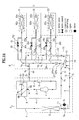
- FIG. 3A illustrates a system showing operation of the system in FIG. 1 in the third operation mode.
- the flow path control valve makes the first port 6a and the second port 6b in communication, and the third port 6c and the fourth port 6d in communication. Therefore, a portion of the refrigerant is introduced from the compressor 1 into he second pipeline 7, and the other portion is introduced into the third pipeline 4. Description of the process, identical to the refrigerant flow in the first operation mode described with reference to FIG. 2A, will be omitted.
- the distributor expansion device 27b is closed.
- the valves 31a and 31b, mounted on the first gas refrigerant branch pipelines 24a and 24b connected to the indoor units C1 and C2 which cool the rooms, are closed, and the valves 32a and 32b mounted on the second gas refrigerant branch pipelines 25a and 25b are opened.
- the valve 31c on the first gas refrigerant branch pipeline 24c connected to the indoor unit C3 which heats the room is opened, and the valve 32c on the second gas refrigerant branch pipeline 25c is closed. Therefore, as shown in FIG.
- the refrigerant passed through the third pipeline 4 and introduced into he gas refrigerant pipeline 23 of the distributor 'B', is introduced into the indoor heat exchanger 62c in the indoor unit C3 via the first gas refrigerant branch pipeline 24c, discharges condensing heat at the indoor heat exchanger 62c to heat the room, and introduced into the liquid refrigerant pipeline 21 via the indoor unit expansion device 61c in a liquid state. Then, the liquid refrigerant introduced into the liquid refrigerant pipeline 21 heat exchanges with the super cooling heat exchanger 71, and super cooled into liquid fully.
- the refrigerant discharged from the compressor 1 to the liquid refrigerant pipeline 21 in the distributor 'B' via the second pipeline 7, joins with the refrigerant introduced into the liquid refrigerant pipeline 21 after heating the room at the indoor unit C3. Then, the joined refrigerant is super cooled into liquid fully at the super cooling means 70, introduced into the indoor unit expansion devices 61a and 61b of the indoor units C1 and C2 through the liquid refrigerant branch pipelines 22a and 22b, vaporized at the indoor heat exchangers 62a and 62b, to cool the rooms, and introduced into the return pipeline 26 via the second gas refrigerant branch pipeline 25a and 25b.
- the refrigerant is introduced from the return pipeline 26 to the fourth pipeline 5 through the third connection pipeline 13, and, therefrom, to the inlet of the compressor 1 via the accumulator 9.
- the noise and the out of order of the indoor expansion devices 61 a and 61b can be reduced significantly, as entire two phased refrigerant is liquefied fully by the super cooling means 70 before introduction into the indoor heat expansion devices 61a and 61b.
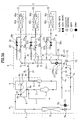
- FIG. 3B illustrates a system showing operation of the system in FIG. 1 in the fourth operation mode.
- the flow path control valve 6 makes the first port 6a and the fourth port 6d in communication and makes the second port 6b and the third port 6d in communication. Therefore, entire refrigerant is introduced from the compressor 1 to the distributor 'B' via the third pipeline 4.
- the distributor expansion device 27b is closed.
- the valves 31a, and 31b on the first gas refrigerant branch pipelines 24a and 24b connected to the indoor units C1 and C2 which heat the rooms are opened, and the valves 32a and 32b on the second gas refrigerant branch pipelines are closed.
- the valve 31c on the first gas refrigerant branch pipeline 24c connected to the indoor unit C3 which cools the room is closed, and the valve 32c on the second gas refrigerant branch pipeline 25c is opened.
- the refrigerant introduced into the gas refrigerant pipeline 23 of the distributor 'B' via the second pipeline 7 is introduced into the indoor heat exchangers 62a and 62b via the first gas refrigerant branch pipelines 24a and 24b, and flows to the liquid refrigerant pipeline 21 via the liquid refrigerant branch pipelines 22a and 22b after heating the rooms at the indoor units C1 and C2.
- the refrigerant introduced into the liquid refrigerant pipeline 21 is introduced into the liquid refrigerant branch pipelines 22c and the other portion of the refrigerant flows toward the first connection pipeline 11.
- the refrigerant introduced into the first connection pipeline 11 is introduced into the fourth pipeline 5 via the second pipeline 7, the parallel pipe piece 7b, the outdoor unit expansion device 7c, the outdoor heat exchanger 2, and the flow path control valve 6.
- the refrigerant introduced into the liquid refrigerant branch pipeline 22c passes through the indoor expansion valve 61 and the indoor heat exchanger 62c of the indoor unit C3, and cools the room, and, therefrom, introduced into the fourth pipeline 5 via the second gas refrigerant branch pipeline 25c, the return pipeline 26, and the third connection pipeline 13. Finally, the refrigerant joined at the fourth pipeline 5 is introduced into the inlet of the compressor 1 via the accumulator 9.
- the noise and out of order of the indoor expansion device 61c and the outdoor expansion device 7c are reduced significantly as the refrigerant liquefied fully by the super cooling means 70 is introduced into the indoor expansion device 61c and the outdoor expansion device 7c.
- the multi-type air conditioner of the present invention has the following advantages.
- the independent cooling or heating of the plurality of rooms can provide an optimal air condition performance proper to an environment of each room.
- liquid refrigerant super cooled by the super cooling means is supplied to the indoor and outdoor expansion devices. According to this, the noise, malfunction, and out of order of the indoor and outdoor expansion devices can be reduced significantly. Moreover, cooling/heating performance is improved as the refrigerating efficiency is improved.
- the invention provides a multi-type air conditioner including an outdoor unit having a compressor, an outdoor heat exchanger, a flow path control valve for controlling a flow path of the refrigerant from the compressor, an outdoor expansion device for expanding liquid refrigerant introduced thereto in a condensed state via indoor units and providing to the outdoor heat exchanger when the room is heated, and an outdoor unit piping system, a plurality of indoor units each having an indoor expansion device, an indoor heat exchanger, and an indoor piping system, a distributor for selectively distributing the refrigerant from the outdoor unit to the indoor units and returning to the outdoor unit again proper to respective operation modes, and means for super cooling the refrigerant condensed at the outdoor heat exchanger or the indoor heat exchangers and flowed to the indoor expansion devices or to the outdoor expansion device, thereby super cooling the refrigerant supplied to the evaporator.
Abstract
Description
- The present invention relates to multi-type air conditioners, and more particularly, to a multi-type air conditioner which can cool or heat a plurality of rooms, individually.
- In general, the air conditioner is an appliance for cooling or heating spaces, such as living spaces, restaurants, and offices. At present, for effective cooling or heating of a space partitioned into many rooms, it is a trend that there has been ceaseless development of multi-type air conditioner. The multi-type air conditioner is in general provided with one outdoor unit and a plurality of indoor units each connected to the outdoor unit and installed in a room, for cooling or heating the room while operating in one of cooling or heating mode.
- However, since the multi-type air conditioner is operative only in one mode of cooling or heating uniformly even if some of the many rooms within the partitioned space require heating, and rest of the rooms require cooling, the multi-type air conditioner has a limit in that the requirement can not be met, properly.
- For an example, even in one building, there are rooms having a temperature difference depending on locations of the rooms or time of the day, such that while a north side room of the building requires heating, a south side room of the building requires cooling due to the sun light, which can not be dealt with a related art multi-type air conditioner that is operative in a single mode.
- Moreover, even though a building equipped with a computer room requires cooling not only in summer, but also in winter for solving the problem of heat load of the computer related equipment, the related art multi-type air conditioner can not deal with such a requirement, properly.
- In conclusion, the requirement demands development of multi-type air conditioner of concurrent cooling/heating type, for making air conditioning of rooms individually, i.e., the indoor unit installed in a room requiring heating is operable in a heating mode, and, at the same time, the indoor unit installed in a room requiring cooling is operable in a cooling mode.
- Accordingly, the present invention is directed to a multi-type air conditioner that substantially obviates one or more of the problems due to limitations and disadvantages of the related art.
- An object of the present invention is to provide a multi-type air conditioner, which can heat or cool rooms individually proper to room requirements at the same time, and in which introduction of two phased refrigerant into an expansion device of an indoor unit is prevented, for preventing deterioration of cooling performance and occurrence of noise.
- Additional features and advantages of the invention will be set forth in the description which follows, and in part will be apparent to those having ordinary skill in the art upon examination of the following or may be learned from practice of the invention. The objectives and other advantages of the invention will be realized and attained by the structure particularly pointed out in the written description and claims hereof as well as the appended drawings.
- To achieve these objects and other advantages and in accordance with the purpose of the present invention, as embodied and broadly described herein, the multi-type air conditioner includes an outdoor unit having a compressor, an outdoor heat exchanger, a flow path control valve for controlling a flow path of the refrigerant from the compressor, an outdoor expansion device for expanding liquid refrigerant introduced thereto in a condensed state via indoor units and providing to the outdoor heat exchanger when the room is heated, and an outdoor unit piping system, a plurality of indoor units each having an indoor expansion device, an indoor heat exchanger, and an indoor piping system, a distributor for selectively distributing the refrigerant from the outdoor unit to the indoor units and returning to the outdoor unit again proper to respective operation modes, and means for super cooling the refrigerant condensed at the outdoor heat exchanger or the indoor heat exchangers and flowed to the indoor expansion devices or to the outdoor expansion device.
- The means includes a super cooling heat exchanger designed so as to heat exchange with a part of a pipeline between the outdoor expansion device and the indoor expansion devices in a pipeline the outdoor heat exchanger, the outdoor expansion device, the indoor expansion devices and the indoor heat exchangers connected in series.
- Preferably, the super cooling heat exchanger uses a part of refrigerant flowing through the refrigerant pipe for super cooling rest of refrigerant passing through a part where the rest of refrigerant heat exchanges with the super cooling heat exchanger.
- To do this, the means further includes a first guide pipe connected between the refrigerant pipeline and one end of the super cooling heat exchanger for guiding a portion of refrigerant flowing through the liquid refrigerant pipeline after having passed through the indoor heat exchanger, a super cooling expansion device mounted on the first guide pipe for expanding the refrigerant flowing through the first guide pipe, and a second guide pipe connected between the inlet of the compressor and the other end of the super cooling heat exchanger for guiding the refrigerant passed through the super cooling heat exchanger to the compressor.
- In the meantime, the means further includes a supplementary super cooling heat exchanger mounted on a refrigerant pipeline between the super cooling heat exchanger and the outdoor expansion device. In this case, the means further includes a first supplementary guide pipe connected between the refrigerant pipeline and one end of the supplementary super cooling heat exchanger, a supplementary super cooling expansion device on the first supplementary guide pipe, and a second supplementary guide pipe connected between the inlet of the compressor and the other end of the supplementary super cooling heat exchanger.
- The super cooling heat exchanger surrounds an outside surface of the refrigerant pipeline. The super cooling heat exchanger passes through an inside of the refrigerant pipeline. The super cooling heat exchanger includes many bends inside of the refrigerant pipeline for enlarging an area of heat exchange with the refrigerant flowing through the refrigerant pipeline.
- In the meantime, the flow path control valve includes a first port in communication with the compressor, a second port in communication with the outdoor heat exchanger, a third port in communication with an inlet of the compressor, and a fourth port connected to a closed pipe piece or blanked.
- The outdoor unit piping system includes a first pipeline connected between an outlet of the compressor and the first port, a second pipeline connected between the second port and the first port of the outdoor unit, the second pipeline having the outdoor heat exchanger mounted in the middle thereof, a third pipeline connected between the first pipeline and the second pipeline of the outdoor unit, and a fourth pipeline connected between the third port and the inlet of the compressor, having the third port of the outdoor unit connected to the middle thereof.
- The first port of the outdoor unit is connected to the first port of the distributor, the second port of the outdoor unit is connected to the second port of the distributor, and the third port of the outdoor unit is connected to the third port of the distributor.
- In the meantime, the distributor includes a distributor piping system for guiding refrigerant from the outdoor unit to the indoor units, and vice versa, and a valve bank mounted on the distributor piping system for controlling flow of refrigerant flowing through the distributor piping system proper to respective operation modes.
- The distributor piping system includes a liquid refrigerant pipeline having a first port of the distributor, a plurality of liquid refrigerant branch pipelines branched from the liquid refrigerant pipeline and connected to the indoor unit expansion devices in the indoor units respectively, a gas refrigerant pipeline having a second port of the distributor, a plurality of first gas refrigerant branch pipelines branched from the gas refrigerant pipeline and connected to the indoor heat exchangers of the indoor units respectively, a plurality of second gas refrigerant branch pipelines branched from intermediate points of the first gas refrigerant branch pipelines respectively, a return pipeline having all the second gas refrigerant pipelines connected thereto, and a third port of the distributor.
- When the air conditioner of the present invention has the foregoing system, it is preferable that the super cooling heat exchanger is mounted at a part where the liquid refrigerant pipeline and the liquid refrigerant branch pipeline join. It is preferable that the first guide pipe is branched from the liquid refrigerant pipeline and connected to the super cooling heat exchanger, and the second guide pipe is connected to the return pipeline.
- In the meantime, in another aspect of the present invention, there is provided a multi-type air conditioner including an outdoor unit having a compressor, and an outdoor heat exchanger, a plurality of indoor units each connected to the outdoor unit directly having an indoor expansion device, and an indoor heat exchanger, and a super cooling heat exchanger mounted on a refrigerant pipeline between the outdoor heat exchanger and the indoor expansion device in the refrigerant pipeline connecting the outdoor heat exchanger, the indoor expansion devices, and the indoor heat exchangers in series, for super cooling the refrigerant.
- It is to be understood that both the foregoing description and the following detailed description of the present invention are exemplary and explanatory and are intended to provide further explanation of the invention claimed.
- The accompanying drawings, which are included to provide a further understanding of the invention and are incorporated in and constitute a part of this application, illustrate embodiment(s) of the invention and together with the description serve to explain the principle of the invention. In the drawings;
- FIG. 1 illustrates a system of a multi-type air conditioner in accordance with a preferred embodiment of the present invention;
- FIG. 2A illustrates a system showing operation of the system in FIG. 1 in cooling all rooms;
- FIG. 2B illustrates a system showing operation of the system in FIG. 1 in heating all rooms;
- FIG. 3A illustrates a system showing operation of the system in FIG. 1 in cooling a major number of rooms and heating a minor number of rooms;
- FIG. 3B illustrates a system showing operation of the system in FIG. 1 in heating a major number of rooms and cooing a minor number of rooms;
- FIG. 4A illustrates a super cooling means in FIG. 4A, schematically;
- FIG. 4B illustrates a section across a line I-I in FIG. 4A;
- FIG. 5 illustrates a P-h diagram showing a super cooling principle of the super cooling means in FIG. 1; and
- FIG. 6 illustrates a system of a multi-type air conditioner in accordance with another preferred embodiment of the present invention.
-
- Reference will now be made in detail to the preferred embodiments of the present invention, examples of which are illustrated in the accompanying drawings. In describing the embodiments of the present invention, same parts will be given the same names and reference symbols, and repetitive description of which will be omitted.
- Referring to FIG. 1, the air conditioner includes an outdoor unit 'A', a distributor 'B', and a plurality of indoor units 'C'; 'C1', 'C2', and 'C3'. The outdoor unit 'A' has a
compressor 1, anoutdoor heat exchanger 2, a flowpath control valve 6, and an outdoor unit piping system, and the distributor 'B' has adistribution piping system 20, and avalve bank 30. Each of the indoor units 'C'; has an indoor heat exchanger 62 and indoor unit expansion device 61. Moreover, the air conditioner of the present invention includes super cooling means 70 additionally for enhancing an air conditioning efficiency and reducing noise and occurrence of out of order of the air conditioner. - The air conditioner has a system in which rooms the indoor units 'C'; 'C1', 'C2', and 'C3' are installed therein respectively are cooled or heated individually according to different operation modes of a first operation mode of cooling all rooms, a second operation mode of heating all rooms, a third operation mode of cooling a major number of the rooms and heating a minor number of rooms, and a fourth operation mode of heating a major number of the rooms and cooling a minor number of rooms, detail of one preferred embodiment of which will be described with reference to FIG. 1.
- For convenience of description, the following drawing reference symbols, 22 represents 22a, 22b, and 22c, 24 represents 24a, 24b, and 24c, 25 represents 25a, 25b, and 25c, 31 represents 31a, 31b, and 31c, 32 represents 32a, 32b, and 32c, 61 represents 61a, 61b, and 61c, 62 represents 62a, 62b, and 62c, and C represents C1, C2, and C3. Of course, a number of the indoor units 'C' and numbers of elements related thereto are varied with a number of rooms, and for convenience of description, the specification describes assuming a case when there are three rooms, i.e., a number of the indoor units are three.
- The outdoor unit 'A' of the air conditioner of the present invention will be described. Referring to FIG 1, there is a first pipeline 3 connected to an outlet of the
compressor 1. The first pipeline 3 is connected to the flowpath control valve 6, which controls a flow path of gas refrigerant from thecompressor 1 according to respective operation modes. The flow path control valve has four ports, of whichfirst port 6a is connected to the first pipeline 3. - The
second port 6b of the flowpath control valve 6 is connected to asecond pipeline 7. Thesecond pipeline 7 has one end connected to thesecond port 6b of the flowpath control valve 6, and the other end connected to a first port A1 of the outdoor unit 'A' as shown in FIG. 1. As shown in FIG. 1, there is theoutdoor heat exchanger 2 in the middle of thesecond pipeline 7. - The
third port 6c of the flow path controlvalve 6 is connected to afourth pipeline 5. Thefourth pipeline 5 has one end connected to thethird port 6c, and the other end connected to an inlet of thecompressor 1. An intermediate point of thefourth pipeline 5 is in communication with the third port A3 of the outdoor unit 'A'. In the meantime, an intermediate point of thefourth pipeline 5, in more detail, at a point between the inlet of thecompressor 1 and the third port A3 of the outdoor unit 'A', there is anaccumulator 9. - As shown in FIG. 1, the
fourth port 6d of the flow path controlvalve 6 is connected to apipe piece 6e with one blanked end. Or, thefourth port 6d may not be connected to the pipe piece, but thefourth port 6d itself may be closed. - The flow path control
valve 6 makes thefirst port 6a and thesecond port 6b in communication and, at the same time with this, makes thethird port 6c and thefourth port 6d in communication when the multi-type air conditioner is in operation in the first or third operation mode. Also, the flow path controlvalve 6 makes thefirst port 6a and thefourth port 6d in communication and, at the same time with this, makes thesecond port 6b and thethird port 6c in communication when the multi-type air conditioner is in operation in the second or fourth operation mode. The refrigerant flow controlled thus by the flow path controlvalve 6 will be described in detail, later. - In the meantime, there is a
third pipeline 4, one end of which is connected to the middle of the first pipeline 3. The other end of thethird pipeline 4 is connected to a second port A2 of the outdoor unit 'A'. There is acheck valve 7a on an intermediate point of thesecond pipeline 7, in more detail, a point between theoutdoor heat exchanger 2 and the first port A1 of the outdoor unit 'A'. It is preferable that thecheck valve 7a is mounted adjacent to theoutdoor heat exchanger 2. There is an outdoorunit expansion device 7c on thesecond pipeline 7 in parallel to thecheck valve 7a. For this, aparallel pipe piece 7b having two ends connected to an inlet and an outlet of thecheck valve 7a is provided, and theoutdoor expansion device 7c is mounted on theparallel pipe piece 7b. - The
check valve 7a passes refrigerant flowing from theoutdoor heat exchanger 2 to the first port A1 of the outdoor unit 'A', and blocks refrigerant flowing from the first port A1 of the outdoor unit 'A' to theoutdoor heat exchanger 2. Therefore, the refrigerant flowing from the first port A1 of the outdoor unit 'A' to theoutdoor heat exchanger 2 bypasses thecheck valve 7a to pass through theparallel pipe 7b and the outdoorunit expansion device 7c, and therefrom flows into theoutdoor heat exchanger 2. - In the meantime, if the
outdoor expansion device 7c can open a flow passage, a function identical to above description can be made even if nocheck valve 7a is provided. That is, if theoutdoor expansion device 7c opens a flow passage, when the refrigerant flows from theoutdoor heat exchanger 2 toward the distributor 'B', and, if theoutdoor expansion device 7c expands the refrigerant, when the refrigerant flows from the distributor 'B' toward theoutdoor heat exchanger 2, the same function as the embodiment in which thecheck valve 7a is provided can be carried out. - The outdoor unit 'A' having the foregoing system is connected to the distributor 'B' with a plurality of connection pipelines. For this, of the connection pipelines, a
first connection pipeline 11 connects the first port A1 of the outdoor unit 'A' to the first port B1 of the distributor 'B', and asecond connection pipeline 12 connects a second port A2 of the outdoor unit 'A' and a second port B2 of the distributor 'B', and athird connection pipeline 13 connects a third port A3 of the outdoor unit 'A' and a third port B3 of the distributor 'B'. Accordingly, in the multi-type air conditioner of the present invention, the outdoor unit 'A' and the distributor 'B' are connected with three pipelines. - In the meantime, it is required that the distributor 'B' guides the refrigerant from the outdoor unit 'A' to selected indoor unit 'C' exactly. Moreover, it is required that the plurality of pipelines connecting the distributor 'B' to the plurality of indoor unit 'C' are simplified, for easy piping work and improving an outer appearance. As shown in FIG. 1, the distributor 'B' of the air conditioner of the present invention designed taken the foregoing matters into account includes the
distributor piping system 20, and thevalve bank 30. - The
distributor piping system 20 guides refrigerant flow from the outdoor unit 'A' to the indoor units 'C', and vice versa. Thedistributor piping system 20 includes a liquidrefrigerant pipeline 21, a plurality of liquidrefrigerant branch pipelines 22, agas refrigerant pipeline 23, and a plurality of firstrefrigerant branch pipelines 24, a plurality of second branch pipelines 25, and areturn pipeline 26. - Referring to FIG. 1, the liquid
refrigerant pipeline 21 provides a first port B1 of the distributor 'B' for connection to thefirst connection pipeline 11. The plurality of liquidrefrigerant branch pipelines 22 are branched from the liquidrefrigerant pipeline 21 and connected to the indoor unit expansion devices 61 in the indoor units 'C', respectively. Thegas refrigerant pipeline 23 provides a second port B2 of the distributor 'B' for connection to thesecond connection pipeline 12. The plurality of first gasrefrigerant branch pipelines 24 are branched from thegas refrigerant pipeline 23 and connected to the indoor heat exchangers 62 of the indoor units C, respectively. The plurality of second gas refrigerant branch pipelines 25 are branched from intermediate points of the first gasrefrigerant branch pipelines 24 respectively. As shown in FIG. 1, thereturn pipeline 26 has all the second gas refrigerant pipelines 25 connected thereto. Thereturn pipe 26 has a third port B3 of the distributor 'B'. - The
valve bank 30 in the distributor 'B' controls refrigerant flow in the distributor piping system, such that gas or liquid refrigerant is introduced into the indoor units in the rooms selectively, and returns from the indoor units 'C' to the outdoor unit 'A'. As shown in FIG. 1, thevalve bank 30 includes a plurality of open/close valves refrigerant branch pipelines 24 and the second gas refrigerant branch pipelines 25, respectively. The valves 31 and 32 open or close the first gasrefrigerant branch pipelines 24 and the second gas refrigerant branch pipelines 25 respectively for controlling refrigerant flow paths according to the operation modes. In the meantime, detailed control of thevalve bank 30 will be described in a description of operation of the air conditioner of the present invention for each operation mode. - The distributor 'B' of the multi-type air conditioner of the present invention may also include means 27 for preventing high pressure refrigerant staying in the
second connection pipeline 12 from being liquefied when the multi-type air conditioner is in the first operation mode. Because there may be shortage of refrigerant for cooling or heating if the high pressure refrigerant is stagnant and liquefied in thesecond connection pipeline 12, themeans 27 is provided to the distributor 'B' for vaporizing liquid refrigerant and preventing liquefaction of the high pressure refrigerant in thesecond connection pipeline 12 to prevent shortage of refrigerant in the air conditioner at the end. The means 27 includes abypass pipe 27a connected between thereturn pipeline 26 and thegas refrigerant pipeline 23, and adistributor expansion device 27b on thebypass pipeline 27a. The operation of themeans 27 will be described in detail, later. - In the meantime, the indoor unit 'C', installed in each room, includes the indoor heat exchanger 62, indoor unit expansion device 61, and room fan (not shown). The indoor heat exchanger 62 is connected to respective first gas
refrigerant branch pipeline 24 in the distributor 'B', and the indoor unit expansion device 61 is connected to respective liquidrefrigerant branch pipeline 22 in the distributor 'B'. The indoor heat exchangers 62 and the indoor unit expansion devices 61 are connected with refrigerant pipe. The room fan blows air to respective indoor heat exchanger 62. - Super cooling means provided to the multi-type air conditioner of the present invention will be described. Before starting description of a structure and mounting location of the super cooling means, necessity for the super cooling means will be described, briefly.
- In general, the outdoor unit 'A' is installed on an outside of a building, such as a roof top of a building, while the indoor units C are installed at respective rooms in the building. The distributor 'B' is installed in the middle of the outdoor unit 'A' and the indoor units C, for an example, a space in the building, or an inside of ceiling. Thus, since the outdoor unit 'A' is installed substantially far from the indoor units 'C', there is a pressure drop taken place when the liquid refrigerant condensed at the outdoor unit 'A' or the indoor units 'C' moves to the indoor units 'C' or the outdoor unit 'A', to cause expansion of a portion of the refrigerant.
- If two phased refrigerant having gas and liquid mixed therein caused by the expansion of a portion of the refrigerant is introduced into the
outdoor expansion device 7c or the indoor expansion device 61, it is liable that noise, malfunction, or out of order may take place when the refrigerant expands. Moreover, a poor expansion efficiency is caused, resulting in a poor air conditioning efficiency. Therefore, in order to solve this problem, an improvement plan is required for super cooling the refrigerant condensed at theoutdoor heat exchanger 2 or at the indoor heat exchangers 62 and supplying to the indoor expansion devices 61 or theoutdoor expansion device 7c. - In order to solve the foregoing problem, the multi-type air conditioner of the present invention includes the super cooling means 70, additionally. Referring to FIG. 1, it is preferable that the super cooling means 70 is mounted on the distributor 'B', for super cooling the refrigerant condensed at the
outdoor heat exchanger 2 or the indoor heat exchangers 62 and flows toward the indoor expansion devices 61 or theoutdoor expansion device 7c. The super cooling means 70 includes a supercooling heat exchanger 71. - The super
cooling heat exchanger 71 is designed so as to heat exchange with a part of a pipeline between theoutdoor expansion device 7c and the indoor expansion devices 61 in a pipeline theoutdoor heat exchanger 2, theoutdoor expansion device 7c, the indoor expansion devices 61 and the indoor heat exchangers connected in series. In more detail, as shown in FIG. 1, the supercooling heat exchanger 71 is mounted on a part the liquidrefrigerant branch pipeline 22 is branched from the liquidrefrigerant pipeline 21. - The super
cooling heat exchanger 71 mounted thus cools down the refrigerant passing through the supercooling heat exchanger 71, resulting to super cool the refrigerant. For cooling the refrigerant passing through the part the supercooling heat exchanger 71 is mounted thereon, a variety of method can be employed. That is, cold air may be blown toward the supercooling heat exchanger 71, or cooling fluid, such as cooling water, may be supplied thereto, for cooling the refrigerant passing through the supercooling heat exchanger 71. However, the present invention suggests not employment of separate cooling fluid, but use of a portion of the refrigerant flowing in the refrigerant pipeline, i.e., the liquidrefrigerant pipeline 21 for cooling the refrigerant passing through the supercooling heat exchanger 71. - To do this, the super
cooling heat exchanger 71 includes afirst guide pipe 72 for guiding a portion of refrigerant flowing through the liquidrefrigerant pipeline 21 to the supercooling heat exchanger 71, a supercooling expansion device 73 for expanding the refrigerant flowing through thefirst guide pipe 72, and asecond guide pipe 74 for guiding the refrigerant passed through the supercooling heat exchanger 71 to the inlet of thecompressor 1. The liquidrefrigerant pipeline 21 has one end connected to a point where the first port B1 of the distributor 'B' and theliquid branch pipeline 22 are branched, and the other end connected to one end of the supercooling heat exchanger 71. As shown in FIG. 1, the supercooling expansion device 73 is mounted on thefirst guide pipe 72. As shown in FIG. 1, thesecond guide pipe 74 has one end connected to the other end of the supercooling expansion device 73, and the other end connected to thereturn pipeline 26. Thus, when the other end of thesecond guide pipe 74 is connected to thereturn pipeline 26, the refrigerant passed through the supercooling expansion device 73 is introduced into the inlet of thecompressor 1 via thereturn pipeline 26 and thefourth pipeline 5. In the meantime, thesecond guide pipe 74 may be connected to thefourth pipeline 5, directly. - Referring to FIG. 4A, the super
cooling heat exchanger 71 may be positioned inside of the liquidrefrigerant pipeline 21. In this instance, as shown in FIGS. 4A and 4B, it is preferable that the supercooling heat exchanger 71 is bent many times in the liquidrefrigerant pipeline 21 for enlarging a heat exchange area with the refrigerant flowing in the liquidrefrigerant pipeline 21 and the liquidrefrigerant branch pipelines 22. Since the refrigerant flowing through the liquidrefrigerant pipeline 21 becomes to contact with the supercooling heat exchanger 71 directly if the supercooling heat exchanger 71 has above form, the refrigerant flowing through the liquidrefrigerant pipeline 21 becomes to heat exchange with the refrigerant flowing through the supercooling heat exchanger 71, effectively. - In the meantime, though FIGS. 4A and 4B illustrate an embodiment in which the liquid
refrigerant pipeline 21 surrounds the supercooling heat exchanger 71, opposite to this, the liquidrefrigerant pipeline 21 may pass through an inside of the supercooling heat exchanger 71. Through not shown, this embodiment can be known to persons in this field of art without any further description. - Referring to FIG. 6, for more positive super cooling of the refrigerant, another super cooling means 80 may be further provided to the air conditioner of the present invention. The super cooling means 80 includes a super
cooling heat exchanger 81, a first guide pipe 82, a super cooling expansion device 83, and asecond guide pipe 84. Description of a structure and connection of the super cooling means 80, similar to the super cooling means 70 described before, will be omitted. However, as shown in FIG. 6, the supercooling heat exchanger 81 is mounted between the first port B1 of the distributor 'B' and the supercooling heat exchanger 71. If the two supercooling heat exchangers cooling heat exchanger 71 is operated in all operation modes. However, the supercooling heat exchanger 81 is operated only in the first operation mode for prevention of drop of an air conditioning performance. - Referring to FIG. 5, a principle in which the refrigerant flowing through the liquid refrigerant is super cooled by the supper cooling means 70 will be described. For reference, FIG. 5 illustrates a P-h diagram showing a super cooling principle of the super cooling means in FIG. 1. For the description will proceed with reference to an embodiment in which the
outdoor heat exchanger 2 serves as a condenser, and the indoor heat exchanger 62 serves as an evaporator. - At first, the refrigerant is compressed to a high pressure at the
compressor 1, and transferred to theoutdoor heat exchanger 2 in FIG. 1 which serves as a condenser, where the refrigerant discharges heat at a fixed pressure, and condensed into liquid refrigerant. The refrigerant liquefied at theoutdoor heat exchanger 2 is transferred to the distributor 'B' via thesecond pipeline 7 in FIG. 1. In this instance, since the refrigerant pipeline connected between the outdoor heat exchanger 'A' and the distributor 'B', i.e., thefirst connection pipeline 11 is long, a pressure of the refrigerant in thefirst connection pipeline 11 drops due to friction taken place in thefirst connection pipeline 11. As a portion of the refrigerant expands while the pressure of the refrigerant drops, the refrigerant becomes a two phased state as shown in FIG. 5. - A portion 'm' of mass of the two phased refrigerant flowing through the
first connection pipeline 11 is introduced into thefirst guide pipe 72, and rest of the mass (1-m) is introduced into the liquidrefrigerant pipeline 21. The portion of mass 'm' of the refrigerant introduced into thefirst guide pipe 72 is expanded completely at the supercooling expansion device 73, heat exchanges at the supercooling heat exchanger 71 with the rest '1-m' of mass of the refrigerant flowing through the liquidrefrigerant pipeline 21, and vaporizes. In this instance, the rest of mass '1-m' of the refrigerant flowing through the liquidrefrigerant pipeline 21 supplies vaporizing heat to the portion 'm' of mass of the refrigerant flowing through the supercooling heat exchanger 71. Therefore, as shown in FIG. 5, the rest '1-m' of mass of the refrigerant flowing through the liquidrefrigerant pipeline 21 is super cooled as the rest '1-m' of mass of the refrigerant is involved in temperature drop with reduced enthalpy under isobaric condition. According to this, entire refrigerant introduced into the indoor expansion device 61 via the liquidrefrigerant pipeline 21 becomes a liquid state. In the meantime, in above process, the supercooling heat exchanger 71 serves as an evaporator for evaporating the portion 'm' of mass of the refrigerant. - The rest '1-m' of mass of the liquid refrigerant super cooled through above process is expanded at the indoor expansion device 61, evaporated at the indoor heat exchanger 62, cools the room, transferred to the
return pipeline 26, and introduced into the inlet of thecompressor 1. On the other hand, the portion 'm' of mass of the refrigerant vaporized at the supercooling heat exchanger 71 is introduced into the inlet of thecompressor 1 via thereturn pipeline 26. - In the multi-type air conditioner of the present invention, so as to be proper to respective operation modes, a flow path and a flow direction of the gas refrigerant from the
compressor 1 are changed under the control of the flow path controlvalve 6 in the outdoor unit 'A', and a flow path and a flow direction of the gas refrigerant are changed under the control of thevalve bank 30 both in the distributor 'B' and the indoor unit 'C', in individual heating or cooling of the rooms. Refrigerant flow under the control of the flow path controlvalve 6 and thevalve bank 30 in the individual cooling or heating of the rooms will be described for each of the operation modes, hereafter. For convenience of description, it is assumed that two indoor units C1 and C2 cool the rooms, and the other one indoor unit C3 heat the room in the third operation mode. It is also assumed that two indoor units C1 and C2 heat the rooms and the other one indoor unit C3 cools the room in the fourth operation mode. - FIG. 2A illustrates a system showing operation of the system in FIG. 1 in cooling all rooms. In the first operation mode when all the indoor units cool the rooms, the flow path control
valve 6 makes thefirst port 6a and thesecond port 6b in communication, and at the same time makes thethird port 6c and thefourth port 6d in communication. Accordingly, most of the refrigerant from the outlet of thecompressor 1 is introduced into thesecond pipeline 7 via the first pipeline 3. As shown in FIG. 2A, a portion of the refrigerant from thecompressor 1 is introduced into thethird pipeline 4 connected to the first pipeline 3. A refrigerant flow introduced into thesecond pipeline 7 from thecompressor 1 will be described. - The refrigerant introduced into the
second pipeline 7 heat exchanges with the external air, and condensed at theoutdoor heat exchanger 2. The portion 'm' of mass of the condensed liquid refrigerant is introduced into the supercooling heat exchanger 71 through thefirst guide pipe 72, and the rest '1-m' of the condensed liquid refrigerant is introduced into the liquidrefrigerant pipeline 21 in the distributor 'B', via thecheck valve 7a, the first port A1 of the outdoor unit 'A', and thefirst connection pipeline 11. As described with reference to FIG. 5, the rest '1-m' of the liquid refrigerant introduced into the liquidrefrigerant pipeline 21 is super cooled into liquid fully as the rest '1-m' of the liquid refrigerant heat exchanges with the portion 'm' of the refrigerant flowing through the supercooling heat exchanger 71. - The portion of mass 'm' of the refrigerant vaporized as it passes through the super
cooling heat exchanger 71 is introduced into the inlet of thecompressor 1 via thesecond guide pipe 74, thereturn pipeline 26, and thefourth pipeline 5. The rest '1-m' of the refrigerant introduced from the liquidrefrigerant pipeline 21 in the distributor 'B' is introduced into the indoor unit expansion devices 61 through the liquidrefrigerant branch pipelines 22, respectively. The refrigerant expanded at the indoor unit expansion devices 61 heat exchanges at the indoor heat exchangers 62 to cool the rooms, respectively. In this instance, since the refrigerant supplied to the indoor expansion devices 61 is in a liquefied state by the super cooling means 70, expansion noise and out of order are reduced significantly compared to the related art. - In the first operation mode, the
valve bank 30 in the distributor 'B' is controlled such that thevalves gas refrigerant pipelines valves gas refrigerant pipelines return pipeline 26 through the second gas refrigerant branch pipelines 25. - In the meantime, the refrigerant, discharged from the
compressor 1 to thethird pipeline 4, is introduced into thegas refrigerant pipeline 23 via the second port A2 of the outdoor unit 'A', thesecond connection pipeline 12, and the second port B2 of the distributor 'B'. In the meantime, as shown in FIG. 2A, since thevalves refrigerant branch pipelines 24 connected to thegas refrigerant pipeline 23 are closed, the gas refrigerant introduced into thegas refrigerant pipeline 23 is guided to thebypass pipeline 27a, and, therefrom, flows to thereturn pipeline 26 after expanded at thedistributor expansion device 27b. Accordingly, themeans 27 prevents liquefaction of the gas refrigerant filled fully in thethird pipeline 4 and thesecond connection pipeline 12 in a stagnant state, effectively. - The gas refrigerant joined at the
return pipeline 26 is introduced into thefourth pipeline 5 via the third port B3 of the distributor 'B', thethird connection pipeline 13, and the third port A3 of the outdoor unit 'A'. In the meantime, thethird port 6c of the flow path controlvalve 6 one end of thefourth pipeline 5 is connected thereto is in communication with thefourth port 6d connected to the blankedpipe piece 6e in the first operation mode. Therefore, the refrigerant is introduced from thefourth pipeline 5 to the inlet of thecompressor 1 via theaccumulator 9. - FIG. 2B illustrates a system showing operation of the system in FIG. 1 in the second operation mode. In the second operation mode, when all rooms are heated, the flow path control
valve 6 makes thefirst port 6a and thefourth port 6d in communication, and at the same time makes thesecond port 6b and thethird port 6c in communication. According to this, as shown in FIG. 2B, entire refrigerant is introduced from thecompressor 1 to thethird pipeline 4 via the first pipeline 3. The gas refrigerant is introduced from thethird pipeline 4 into thegas refrigerant pipeline 23 via the second port A2 of the outdoor unit 'A', thesecond connection pipeline 12, and the second port of the distributor 'B'. - In the second operation mode, the
distributor expansion device 27b is closed, thevalves refrigerant branch pipelines 24 are opened, and thevalve gas refrigerant pipeline 23 is introduced into the first gasrefrigerant branch pipelines 24, and heat exchanges with room air, and is condensed at the indoor heat exchangers 62. In this instance, the indoor heat exchanger 62 discharges condensing heat, and the room fan (not shown) discharges the condensing heat into the room, to heat the room. - As shown in FIG. 2B, since the indoor unit expansion device 61 is opened in the second operation mode, the refrigerant condensed at the indoor heat exchanger 62 is introduced into the liquid
refrigerant pipeline 21 through the liquidrefrigerant branch pipelines 22. In this instance, as shown in FIG. 2B, the refrigerant flowing through the liquidrefrigerant pipeline 21 heat exchanges with the supercooling heat exchanger 71, is super cooled, and introduced into thesecond pipeline 7 via the first port B1 of the distributor 'B', thefirst connection pipeline 11, and the first port A1 of the outdoor unit 'A'. The description of the principle of super cooling by the super cooling means 70, similar to the description made with reference to FIG. 5, will be omitted. - The refrigerant is introduced from the
second pipeline 7 to theparallel pipe piece 7b under the guidance of thecheck valve 7a, and expanded at theoutdoor expansion valve 7c. In this instance, the refrigerant introduced into theoutdoor heat exchanger 7c is in a super cooled state by the super cooling means 70 fully, the noise and out of order of theoutdoor expansion device 7c is reduced significantly. The refrigerant expanded at theoutdoor expansion device 7c heat exchanges, and is vaporized at theoutdoor heat exchanger 2. Then, the vaporized refrigerant is introduced into thefourth pipeline 5 guided by the flow path controlvalve 6, and enters into the inlet of thecompressor 1 via theaccumulator 9. In this instance, since thevalves fourth pipeline 5 to thecompressor 1. - FIG. 3A illustrates a system showing operation of the system in FIG. 1 in the third operation mode. Identical to the first operation mode, in the third operation mode, when a major number of rooms are cooled, and a minor number of rooms are heated, the flow path control valve makes the
first port 6a and thesecond port 6b in communication, and thethird port 6c and thefourth port 6d in communication. Therefore, a portion of the refrigerant is introduced from thecompressor 1 into hesecond pipeline 7, and the other portion is introduced into thethird pipeline 4. Description of the process, identical to the refrigerant flow in the first operation mode described with reference to FIG. 2A, will be omitted. - In the third operation mode, the
distributor expansion device 27b is closed. Thevalves refrigerant branch pipelines valves refrigerant branch pipelines valve 31c on the first gasrefrigerant branch pipeline 24c connected to the indoor unit C3 which heats the room is opened, and thevalve 32c on the second gasrefrigerant branch pipeline 25c is closed. Therefore, as shown in FIG. 3A, the refrigerant, passed through thethird pipeline 4 and introduced into he gasrefrigerant pipeline 23 of the distributor 'B', is introduced into theindoor heat exchanger 62c in the indoor unit C3 via the first gasrefrigerant branch pipeline 24c, discharges condensing heat at theindoor heat exchanger 62c to heat the room, and introduced into the liquidrefrigerant pipeline 21 via the indoorunit expansion device 61c in a liquid state. Then, the liquid refrigerant introduced into the liquidrefrigerant pipeline 21 heat exchanges with the supercooling heat exchanger 71, and super cooled into liquid fully. - Referring to FIG. 3A, the refrigerant, discharged from the
compressor 1 to the liquidrefrigerant pipeline 21 in the distributor 'B' via thesecond pipeline 7, joins with the refrigerant introduced into the liquidrefrigerant pipeline 21 after heating the room at the indoor unit C3. Then, the joined refrigerant is super cooled into liquid fully at the super cooling means 70, introduced into the indoorunit expansion devices refrigerant branch pipelines indoor heat exchangers return pipeline 26 via the second gasrefrigerant branch pipeline return pipeline 26 to thefourth pipeline 5 through thethird connection pipeline 13, and, therefrom, to the inlet of thecompressor 1 via theaccumulator 9. In the third operation mode too, the noise and the out of order of theindoor expansion devices heat expansion devices - FIG. 3B illustrates a system showing operation of the system in FIG. 1 in the fourth operation mode. In the fourth operation mode, when a major number of rooms are heated and a minor number of rooms are cooled, the flow path control
valve 6 makes thefirst port 6a and thefourth port 6d in communication and makes thesecond port 6b and thethird port 6d in communication. Therefore, entire refrigerant is introduced from thecompressor 1 to the distributor 'B' via thethird pipeline 4. - In the fourth operation mode, the
distributor expansion device 27b is closed. Thevalves refrigerant branch pipelines valves valve 31c on the first gasrefrigerant branch pipeline 24c connected to the indoor unit C3 which cools the room is closed, and thevalve 32c on the second gasrefrigerant branch pipeline 25c is opened. Therefore, the refrigerant introduced into thegas refrigerant pipeline 23 of the distributor 'B' via thesecond pipeline 7 is introduced into theindoor heat exchangers refrigerant branch pipelines refrigerant pipeline 21 via the liquidrefrigerant branch pipelines - Referring to FIG. 3B, after liquefied fully by the super cooling means 70, a portion of the refrigerant introduced into the liquid
refrigerant pipeline 21 is introduced into the liquidrefrigerant branch pipelines 22c and the other portion of the refrigerant flows toward thefirst connection pipeline 11. In this instance, the refrigerant introduced into thefirst connection pipeline 11 is introduced into thefourth pipeline 5 via thesecond pipeline 7, theparallel pipe piece 7b, the outdoorunit expansion device 7c, theoutdoor heat exchanger 2, and the flow path controlvalve 6. - The refrigerant introduced into the liquid
refrigerant branch pipeline 22c passes through the indoor expansion valve 61 and theindoor heat exchanger 62c of the indoor unit C3, and cools the room, and, therefrom, introduced into thefourth pipeline 5 via the second gasrefrigerant branch pipeline 25c, thereturn pipeline 26, and thethird connection pipeline 13. Finally, the refrigerant joined at thefourth pipeline 5 is introduced into the inlet of thecompressor 1 via theaccumulator 9. In the third mode too, the noise and out of order of theindoor expansion device 61c and theoutdoor expansion device 7c are reduced significantly as the refrigerant liquefied fully by the super cooling means 70 is introduced into theindoor expansion device 61c and theoutdoor expansion device 7c. - As has been described, the multi-type air conditioner of the present invention has the following advantages.
- First, the independent cooling or heating of the plurality of rooms can provide an optimal air condition performance proper to an environment of each room.
- Second, liquid refrigerant super cooled by the super cooling means is supplied to the indoor and outdoor expansion devices. According to this, the noise, malfunction, and out of order of the indoor and outdoor expansion devices can be reduced significantly. Moreover, cooling/heating performance is improved as the refrigerating efficiency is improved.
- In the meantime, a multi-unit air conditioner has been described, in which one outdoor unit, one distributor, and a plurality of indoor units are provided for independent cooling or heating of rooms. It will be apparent to those skilled in the art that various modifications and variations can be made in the present invention without departing from the spirit or scope of the invention. For an example, in the case of the multi-type air conditioner having one outdoor unit and a plurality of indoor units connected to the one outdoor unit directly, all of the plurality of rooms can be heated or cooled. In this case too, it is apparent to persons skilled in this field of art that the super cooling means may be mounted on pipelines connected between the outdoor unit and the indoor units, so that the super cooling means serve the same function as the foregoing embodiments. Thus, it is intended that the present invention cover the modifications and variations of this invention provided they come within the scope of the appended claims and their equivalents.
- In summary, the invention provides a multi-type air conditioner including an outdoor unit having a compressor, an outdoor heat exchanger, a flow path control valve for controlling a flow path of the refrigerant from the compressor, an outdoor expansion device for expanding liquid refrigerant introduced thereto in a condensed state via indoor units and providing to the outdoor heat exchanger when the room is heated, and an outdoor unit piping system, a plurality of indoor units each having an indoor expansion device, an indoor heat exchanger, and an indoor piping system, a distributor for selectively distributing the refrigerant from the outdoor unit to the indoor units and returning to the outdoor unit again proper to respective operation modes, and means for super cooling the refrigerant condensed at the outdoor heat exchanger or the indoor heat exchangers and flowed to the indoor expansion devices or to the outdoor expansion device, thereby super cooling the refrigerant supplied to the evaporator.
Claims (18)
- A multi-type air conditioner comprising:an outdoor unit (A) having a compressor (1), an outdoor heat exchanger (2), a flow path control valve (6) for controlling a flow path of the refrigerant from the compressor (1), an outdoor expansion device (7c) for expanding liquid refrigerant introduced thereto in a condensed state via indoor units (C) and providing to the outdoor heat exchanger (2) when the room is heated, and an outdoor unit piping system (3,4,5,7);a plurality of indoor units (C;C1,C2,C3) each having an indoor expansion device (61), an indoor heat exchanger (62), and an indoor piping system;a distributor (B) for selectively distributing the refrigerant from the outdoor unit (A) to the indoor units (C) and returning to the outdoor unit (A) again proper to respective operation modes; andmeans (70) for super cooling the refrigerant condensed at the outdoor heat exchanger (2) or the indoor heat exchangers (62) and flowed to the indoor expansion devices (61) or to the outdoor expansion device (7c).
- The multi-type air conditioner as claimed in claim 1, wherein the means (70) includes a super cooling heat exchanger (71) designed so as to heat exchange with a part of a pipeline (21) between the outdoor expansion device (7c) and the indoor expansion devices (61) in a pipeline, the outdoor heat exchanger (2), the outdoor expansion device (7c), the indoor expansion devices (61) and the indoor heat exchangers (62) connected in series.
- A multi-type air conditioner comprising:an outdoor unit (A) having a compressor (1), and an outdoor heat exchanger (2);a plurality of indoor units (C) each connected to the outdoor unit (A) directly, having an indoor expansion device (61), and an indoor heat exchanger (62); anda super cooling heat exchanger (71) mounted on a refrigerant pipeline (21) between the outdoor heat exchanger (2) and the indoor expansion device (61) in the refrigerant pipeline (21) connecting the outdoor heat exchanger (2), the indoor expansion devices (61), and the indoor heat exchangers (62) in series, for super cooling the refrigerant.
- The multi-type air conditioner as claimed in claim 2 or 3, wherein the super cooling heat exchanger (71) uses a part of refrigerant flowing through the refrigerant pipe (21) for super cooling rest of refrigerant passing through a part where the rest of refrigerant heat exchanges with the super cooling heat exchanger (71).
- The multi-type air conditioner as claimed in any of the preceding claims, wherein the means (70) further includes;a first guide pipe (72) connected between the refrigerant pipeline (21) and one end of the super cooling heat exchanger (71) for guiding, in particular bypassing and guiding, a portion of refrigerant flowing through the liquid refrigerant pipeline (21) after having passed through the indoor heat exchanger (62),a super cooling expansion device (73) mounted on the first guide pipe (72) for expanding the refrigerant flowing through the first guide pipe (72), anda second guide pipe (74) connected between the inlet of the compressor (1) and the other end of the super cooling heat exchanger (71) for guiding the refrigerant passed through the super cooling heat exchanger (71) to the compressor (1).
- The multi-type air conditioner as claimed in any one of claims 2 to 5, wherein the super cooling heat exchanger (71) surrounds an outside surface of the refrigerant pipeline (21).
- The multi-type air conditioner as claimed in any one of claims 2 to 5, wherein the super cooling heat exchanger (71) passes through an inside of the refrigerant pipeline (21).
- The multi-type air conditioner as claimed in any one of claims 2 to 7, wherein the super cooling heat exchanger (71) includes many bends for enlarging an area of heat exchange with the refrigerant flowing through the refrigerant pipeline (21).
- The multi-type air conditioner as claimed in any one of claims 2 to 8, wherein the super cooling heat exchanger (71) is tubular.
- The multi-type air conditioner as claimed in any one of the preceding claims, wherein the means (70) further includes a supplementary super cooling heat exchanger (81) mounted on a refrigerant pipeline between the super cooling heat exchanger (71) and the outdoor expansion device (7c).
- The multi-type air conditioner as claimed in claim 10, wherein the means (70) further includes;a first supplementary guide pipe (82) connected between the refrigerant pipeline (21) and one end of the supplementary super cooling heat exchanger (81),a supplementary super cooling expansion device (83) on the first supplementary guide pipe (82), anda second supplementary guide pipe (84) connected between the inlet of the compressor (1) and the other end of the supplementary super cooling heat exchanger (81).
- The multi-type air conditioner as claimed in any of the preceding claims, wherein the flow path control valve (6) includes;a first port (6a) in communication with the compressor (1),a second port (6b) in communication with the outdoor heat exchanger (2),a third port (6c) in communication with an inlet of the compressor (1), anda fourth port (6d) connected to a closed pipe piece (6e) or blanked.
- The multi-type air conditioner as claimed in claim 12, wherein the outdoor unit piping system includes;a first pipeline (3) connected between an outlet of the compressor (1) and the first port (6a),a second pipeline (7) connected between the second port (6b) and the first port (A1) of the outdoor unit (A), the second pipeline (7) having the outdoor heat exchanger (2) mounted in the middle thereof,a third pipeline (4) connected between the first pipeline (3) and the second pipeline (7) of the outdoor unit (A), anda fourth pipeline (5) connected between the third port (6c) and the inlet of the compressor (1), having the third port (A3) of the outdoor unit (A) connected to the middle thereof.
- The multi-type air conditioner as claimed in claim 13, wherein the first port (A1) of the outdoor unit (A) is connected to the first port (B1) of the distributor (B), the second port (A2) of the outdoor unit (A) is connected to the second port (B2) of the distributor (B), and the third port (A3) of the outdoor unit (A) is connected to the third port (B3) of the distributor (B).
- The multi-type air conditioner as claimed in claim 14, wherein the distributor (B) includes;a distributor piping system (20) for guiding refrigerant from the outdoor unit (A) to the indoor units (C), and vice versa, anda valve bank (30) mounted on the distributor piping system (20) for controlling flow of refrigerant flowing through the distributor piping system (20) proper to respective operation modes.
- The multi-type air conditioner as claimed in claim 15, wherein the distributor piping system (20) includes;a liquid refrigerant pipeline (21) having a first port (B1) of the distributor (B),a plurality of liquid refrigerant branch pipelines (22) branched from the liquid refrigerant pipeline (21) and connected to the indoor unit expansion devices (61) in the indoor units (C) respectively,a gas refrigerant pipeline (23) having a second port (B2) of the distributor (B),a plurality of first gas refrigerant branch pipelines (24) branched from the gas refrigerant pipeline (23) and connected to the indoor heat exchangers (62) of the indoor units (C) respectively,a plurality of second gas refrigerant branch pipelines (25) branched from intermediate points of the first gas refrigerant branch pipelines (24) respectively,a return pipeline (26) having all the second gas refrigerant pipelines connected thereto, and a third port (B3) of the distributor (B).
- The multi-type air conditioner as claimed in claim 16, wherein the means (70) includes a super cooling heat exchanger (71) mounted on a part the liquid refrigerant branch pipeline branches (22) from the liquid refrigerant pipeline (21) for heat exchange with the refrigerant introduced into, or discharged from the outdoor unit (A).
- The multi-type air conditioner as claimed in claim 17, wherein the means (70) further includes;a first guide pipe (72) connected between the refrigerant pipeline (21) and one end of the super cooling heat exchanger (71),a super cooling expansion device (73) mounted on the first guide pipe (72) for expanding the refrigerant flowing through the first guide pipe (72), anda second guide pipe (74) connected between the other end of the super cooling heat exchanger (71) and the return pipeline (26).
Applications Claiming Priority (2)
| Application Number | Priority Date | Filing Date | Title |
|---|---|---|---|
| KR2003002035 | 2003-01-13 | ||
| KR10-2003-0002035A KR100504498B1 (en) | 2003-01-13 | 2003-01-13 | Air conditioner |
Publications (3)
| Publication Number | Publication Date |
|---|---|
| EP1437555A2 true EP1437555A2 (en) | 2004-07-14 |
| EP1437555A3 EP1437555A3 (en) | 2004-12-08 |
| EP1437555B1 EP1437555B1 (en) | 2008-05-21 |
Family
ID=32501505
Family Applications (1)
| Application Number | Title | Priority Date | Filing Date |
|---|---|---|---|
| EP03023594A Expired - Fee Related EP1437555B1 (en) | 2003-01-13 | 2003-10-16 | Multi-type air conditioner |
Country Status (6)
| Country | Link |
|---|---|
| US (1) | US6918264B2 (en) |
| EP (1) | EP1437555B1 (en) |
| JP (1) | JP4643135B2 (en) |
| KR (1) | KR100504498B1 (en) |
| CN (1) | CN1272594C (en) |
| DE (1) | DE60321119D1 (en) |
Cited By (6)
| Publication number | Priority date | Publication date | Assignee | Title |
|---|---|---|---|---|
| EP1559969A1 (en) * | 2004-01-27 | 2005-08-03 | Lg Electronics Inc. | Air conditioner |
| CN100351588C (en) * | 2004-11-26 | 2007-11-28 | Lg电子株式会社 | Air conditioning system |
| EP1998123A1 (en) * | 2006-03-22 | 2008-12-03 | Daikin Industries, Ltd. | Refrigerating apparatus |
| EP1686331A3 (en) * | 2004-12-28 | 2009-01-14 | Lg Electronics Inc. | Supercooling apparatus of a multiple air conditioner |
| EP3101369A4 (en) * | 2014-01-27 | 2017-08-09 | Qingdao Hisense Hitachi Air-Conditioning Systems Co. Ltd. | Heat recovery variable-frequency multi-split heat pump system and control method thereof |
| CN108036551A (en) * | 2017-12-18 | 2018-05-15 | 广东美的暖通设备有限公司 | Switching device and there is its multi-gang air-conditioner |
Families Citing this family (23)
| Publication number | Priority date | Publication date | Assignee | Title |
|---|---|---|---|---|
| KR100463548B1 (en) * | 2003-01-13 | 2004-12-29 | 엘지전자 주식회사 | Air conditioner |
| DE10346823A1 (en) * | 2003-10-06 | 2005-04-21 | Behr Gmbh & Co Kg | Air conditioning system for motor vehicle, comprises a device for reversing the flow direction of the refrigerant for the heat pump operation |
| KR100504902B1 (en) * | 2003-10-27 | 2005-07-29 | 엘지전자 주식회사 | Air conditioner with out door units and refrigerant control method thereof |
| JP3861891B2 (en) * | 2004-08-04 | 2006-12-27 | ダイキン工業株式会社 | Air conditioner |
| KR100619775B1 (en) * | 2005-02-15 | 2006-09-11 | 엘지전자 주식회사 | Multi-air conditioner capable of cooling and heating simultaneously |
| KR100682269B1 (en) * | 2005-10-05 | 2007-02-15 | 엘지전자 주식회사 | Heat exchanger unit for improving heat exchange efficiency and air conditioning apparatus having the same |
| KR100701769B1 (en) * | 2005-10-28 | 2007-03-30 | 엘지전자 주식회사 | Method for controlling air conditioner |
| JP2010159896A (en) * | 2009-01-06 | 2010-07-22 | Fuji Electric Retail Systems Co Ltd | Refrigerant circuit device |
| WO2011052046A1 (en) * | 2009-10-28 | 2011-05-05 | 三菱電機株式会社 | Air conditioning device |
| JP5323202B2 (en) * | 2009-10-29 | 2013-10-23 | 三菱電機株式会社 | Air conditioner |
| US9335072B2 (en) * | 2010-03-25 | 2016-05-10 | Mitsubishi Electric Corporation | Air-conditioning apparatus |
| WO2012011688A2 (en) * | 2010-07-21 | 2012-01-26 | Chungju National University Industrial Cooperation Foundation | Alternating type heat pump |
| CN102183104B (en) * | 2011-03-31 | 2012-07-04 | 浙江大学 | Indirect-expanding solar assisted multifunctional heat pump system |
| KR101910658B1 (en) * | 2011-07-18 | 2018-10-23 | 삼성전자주식회사 | Multi type air conditioner |
| KR101319778B1 (en) * | 2011-10-27 | 2013-10-17 | 엘지전자 주식회사 | Air conditioner |
| KR101873597B1 (en) * | 2012-02-23 | 2018-07-31 | 엘지전자 주식회사 | An air conditioner |
| US20150211776A1 (en) * | 2012-10-01 | 2015-07-30 | Mitsubishi Electric Corporation | Air-conditioning apparatus |
| KR102122587B1 (en) * | 2013-04-18 | 2020-06-15 | 엘지전자 주식회사 | An air conditioning system |
| JP5812084B2 (en) * | 2013-12-11 | 2015-11-11 | ダイキン工業株式会社 | Channel switching collective unit and method for manufacturing channel switching collective unit |
| US20160033145A1 (en) * | 2014-07-29 | 2016-02-04 | Twin Harbor Labs, LLC | Room-to-Room Heat Pump |
| KR101726073B1 (en) * | 2015-10-01 | 2017-04-11 | 엘지전자 주식회사 | Air conditioning system |
| JP6787007B2 (en) * | 2016-09-30 | 2020-11-18 | ダイキン工業株式会社 | Air conditioner |
| CN113819593A (en) * | 2021-08-16 | 2021-12-21 | 青岛海尔空调器有限总公司 | Air conditioner refrigerant flow control method and device and air conditioner |
Citations (5)
| Publication number | Priority date | Publication date | Assignee | Title |
|---|---|---|---|---|
| EP0485203A1 (en) * | 1990-11-08 | 1992-05-13 | Mitsubishi Denki Kabushiki Kaisha | Air conditioning system |
| EP0496505A2 (en) * | 1991-01-10 | 1992-07-29 | Mitsubishi Denki Kabushiki Kaisha | Air-conditioning system |
| EP0974792A2 (en) * | 1998-07-23 | 2000-01-26 | Eaton-Williams Group Limited | Heat exchange equipment |
| WO2001081834A1 (en) * | 2000-04-24 | 2001-11-01 | Daikin Industries, Ltd. | Branch unit for air conditioner |
| EP1162414A1 (en) * | 1999-02-17 | 2001-12-12 | Yanmar Diesel Engine Co. Ltd. | Refrigerant supercooling circuit |
Family Cites Families (7)
| Publication number | Priority date | Publication date | Assignee | Title |
|---|---|---|---|---|
| JPH0426847Y2 (en) * | 1987-04-14 | 1992-06-26 | ||
| JPH04254167A (en) * | 1991-02-05 | 1992-09-09 | Matsushita Refrig Co Ltd | Multi-room type air-contiditioning machine |
| AU649810B2 (en) * | 1991-05-09 | 1994-06-02 | Mitsubishi Denki Kabushiki Kaisha | Air conditioning apparatus |
| JP2974179B2 (en) | 1991-10-09 | 1999-11-08 | 松下冷機株式会社 | Multi-room air conditioner |
| JPH05172419A (en) * | 1991-12-24 | 1993-07-09 | Mitsubishi Heavy Ind Ltd | Air conditioner |
| JPH05172420A (en) * | 1991-12-24 | 1993-07-09 | Mitsubishi Heavy Ind Ltd | Air conditioner |
| JPH1054616A (en) | 1996-08-14 | 1998-02-24 | Daikin Ind Ltd | Air conditioner |
-
2003
- 2003-01-13 KR KR10-2003-0002035A patent/KR100504498B1/en not_active IP Right Cessation
- 2003-10-14 US US10/682,972 patent/US6918264B2/en not_active Expired - Lifetime
- 2003-10-16 DE DE60321119T patent/DE60321119D1/en not_active Expired - Lifetime
- 2003-10-16 EP EP03023594A patent/EP1437555B1/en not_active Expired - Fee Related
- 2003-10-20 JP JP2003359518A patent/JP4643135B2/en not_active Expired - Fee Related
- 2003-10-20 CN CNB2003101156818A patent/CN1272594C/en not_active Expired - Fee Related
Patent Citations (5)
| Publication number | Priority date | Publication date | Assignee | Title |
|---|---|---|---|---|
| EP0485203A1 (en) * | 1990-11-08 | 1992-05-13 | Mitsubishi Denki Kabushiki Kaisha | Air conditioning system |
| EP0496505A2 (en) * | 1991-01-10 | 1992-07-29 | Mitsubishi Denki Kabushiki Kaisha | Air-conditioning system |
| EP0974792A2 (en) * | 1998-07-23 | 2000-01-26 | Eaton-Williams Group Limited | Heat exchange equipment |
| EP1162414A1 (en) * | 1999-02-17 | 2001-12-12 | Yanmar Diesel Engine Co. Ltd. | Refrigerant supercooling circuit |
| WO2001081834A1 (en) * | 2000-04-24 | 2001-11-01 | Daikin Industries, Ltd. | Branch unit for air conditioner |
Cited By (12)
| Publication number | Priority date | Publication date | Assignee | Title |
|---|---|---|---|---|
| EP1559969A1 (en) * | 2004-01-27 | 2005-08-03 | Lg Electronics Inc. | Air conditioner |
| CN100351588C (en) * | 2004-11-26 | 2007-11-28 | Lg电子株式会社 | Air conditioning system |
| EP1686331A3 (en) * | 2004-12-28 | 2009-01-14 | Lg Electronics Inc. | Supercooling apparatus of a multiple air conditioner |
| US7805961B2 (en) | 2004-12-28 | 2010-10-05 | Lg Electronics Inc. | Supercooling apparatus of simultaneous cooling and heating type multiple air conditioner |
| EP2306123A1 (en) * | 2004-12-28 | 2011-04-06 | LG Electronics, Inc. | Supercooling apparatus of a multiple air conditioner |
| EP1998123A1 (en) * | 2006-03-22 | 2008-12-03 | Daikin Industries, Ltd. | Refrigerating apparatus |
| EP1998123A4 (en) * | 2006-03-22 | 2011-03-02 | Daikin Ind Ltd | Refrigerating apparatus |
| EP3101369A4 (en) * | 2014-01-27 | 2017-08-09 | Qingdao Hisense Hitachi Air-Conditioning Systems Co. Ltd. | Heat recovery variable-frequency multi-split heat pump system and control method thereof |
| US10132530B2 (en) | 2014-01-27 | 2018-11-20 | Qingdao Hisense Hitachi Air-conditioning Systems Co., Ltd. | Heat recovery variable-frequency multi-split heat pump system and control method thereof |
| US20190032968A1 (en) * | 2014-01-27 | 2019-01-31 | Qingdao Hisense Hitachi Air-conditioning Systems Co., Ltd. | Outdoor Unit of an Air Conditioning System, Air Conditioning System, and Control Method Thereof |
| US11035597B2 (en) * | 2014-01-27 | 2021-06-15 | Qingdao Hisense Hitachi Air-conditioning Systems Co., Ltd. | Outdoor unit of an air conditioning system, air conditioning system, and control method thereof |
| CN108036551A (en) * | 2017-12-18 | 2018-05-15 | 广东美的暖通设备有限公司 | Switching device and there is its multi-gang air-conditioner |
Also Published As
| Publication number | Publication date |
|---|---|
| JP4643135B2 (en) | 2011-03-02 |
| US20040134215A1 (en) | 2004-07-15 |
| DE60321119D1 (en) | 2008-07-03 |
| KR20040064453A (en) | 2004-07-19 |
| CN1517609A (en) | 2004-08-04 |
| EP1437555A3 (en) | 2004-12-08 |
| EP1437555B1 (en) | 2008-05-21 |
| KR100504498B1 (en) | 2005-08-03 |
| US6918264B2 (en) | 2005-07-19 |
| CN1272594C (en) | 2006-08-30 |
| JP2004219046A (en) | 2004-08-05 |
Similar Documents
| Publication | Publication Date | Title |
|---|---|---|
| EP1437555B1 (en) | Multi-type air conditioner | |
| US7716941B2 (en) | Multi-type air conditioner with defrosting device | |
| US7124595B2 (en) | Multi-type air conditioner with plurality of distributor able to be shutoff | |
| EP1391660B1 (en) | Multi-unit air conditioner and method for controlling operation of outdoor unit fan thereof | |
| US6772600B2 (en) | Multi-unit air conditioner and method for controlling the same | |
| US6883345B2 (en) | Multi-type air conditioner and method for operating the same | |
| JP4358559B2 (en) | Multi air conditioner | |
| EP1437556B1 (en) | Multi-type air conditioner | |
| US6952933B2 (en) | Multi-type air conditioner | |
| EP1391664A2 (en) | Multi-unit air conditioner and method for controlling operation of outdoor unit fan thereof | |
| KR100677267B1 (en) | Distribution unit for multi type air conditioner of which indoor units are driven as a cooler or as a heater respectively at a same time | |
| KR100504499B1 (en) | Multi-type air conditioner for cooling/heating the same time | |
| KR100215038B1 (en) | Indoor device connection structure of multi-airconditioner |
Legal Events
| Date | Code | Title | Description |
|---|---|---|---|
| PUAI | Public reference made under article 153(3) epc to a published international application that has entered the european phase |
Free format text: ORIGINAL CODE: 0009012 |
|
| 17P | Request for examination filed |
Effective date: 20031022 |
|
| AK | Designated contracting states |
Kind code of ref document: A2 Designated state(s): AT BE BG CH CY CZ DE DK EE ES FI FR GB GR HU IE IT LI LU MC NL PT RO SE SI SK TR |
|
| AX | Request for extension of the european patent |
Extension state: AL LT LV MK |
|
| PUAL | Search report despatched |
Free format text: ORIGINAL CODE: 0009013 |
|
| AK | Designated contracting states |
Kind code of ref document: A3 Designated state(s): AT BE BG CH CY CZ DE DK EE ES FI FR GB GR HU IE IT LI LU MC NL PT RO SE SI SK TR |
|
| AX | Request for extension of the european patent |
Extension state: AL LT LV MK |
|
| AKX | Designation fees paid |
Designated state(s): DE FR GB IT |
|
| 17Q | First examination report despatched |
Effective date: 20070508 |
|
| GRAP | Despatch of communication of intention to grant a patent |
Free format text: ORIGINAL CODE: EPIDOSNIGR1 |
|
| GRAS | Grant fee paid |
Free format text: ORIGINAL CODE: EPIDOSNIGR3 |
|
| GRAA | (expected) grant |
Free format text: ORIGINAL CODE: 0009210 |
|
| AK | Designated contracting states |
Kind code of ref document: B1 Designated state(s): DE FR GB IT |
|
| REG | Reference to a national code |
Ref country code: GB Ref legal event code: FG4D |
|
| REF | Corresponds to: |
Ref document number: 60321119 Country of ref document: DE Date of ref document: 20080703 Kind code of ref document: P |
|
| PLBE | No opposition filed within time limit |
Free format text: ORIGINAL CODE: 0009261 |
|
| STAA | Information on the status of an ep patent application or granted ep patent |
Free format text: STATUS: NO OPPOSITION FILED WITHIN TIME LIMIT |
|
| 26N | No opposition filed |
Effective date: 20090224 |
|
| REG | Reference to a national code |
Ref country code: FR Ref legal event code: PLFP Year of fee payment: 14 |
|
| REG | Reference to a national code |
Ref country code: FR Ref legal event code: PLFP Year of fee payment: 15 |
|
| PGFP | Annual fee paid to national office [announced via postgrant information from national office to epo] |
Ref country code: GB Payment date: 20170906 Year of fee payment: 15 Ref country code: FR Payment date: 20170907 Year of fee payment: 15 |
|
| PGFP | Annual fee paid to national office [announced via postgrant information from national office to epo] |
Ref country code: IT Payment date: 20171011 Year of fee payment: 15 |
|
| GBPC | Gb: european patent ceased through non-payment of renewal fee |
Effective date: 20181016 |
|
| PG25 | Lapsed in a contracting state [announced via postgrant information from national office to epo] |
Ref country code: FR Free format text: LAPSE BECAUSE OF NON-PAYMENT OF DUE FEES Effective date: 20181031 |
|
| PG25 | Lapsed in a contracting state [announced via postgrant information from national office to epo] |
Ref country code: GB Free format text: LAPSE BECAUSE OF NON-PAYMENT OF DUE FEES Effective date: 20181016 Ref country code: IT Free format text: LAPSE BECAUSE OF NON-PAYMENT OF DUE FEES Effective date: 20181016 |
|
| PGFP | Annual fee paid to national office [announced via postgrant information from national office to epo] |
Ref country code: DE Payment date: 20190905 Year of fee payment: 17 |
|
| REG | Reference to a national code |
Ref country code: DE Ref legal event code: R119 Ref document number: 60321119 Country of ref document: DE |
|
| PG25 | Lapsed in a contracting state [announced via postgrant information from national office to epo] |
Ref country code: DE Free format text: LAPSE BECAUSE OF NON-PAYMENT OF DUE FEES Effective date: 20210501 |