EP1437516B1 - Driving unit - Google Patents
Driving unit Download PDFInfo
- Publication number
- EP1437516B1 EP1437516B1 EP04100531A EP04100531A EP1437516B1 EP 1437516 B1 EP1437516 B1 EP 1437516B1 EP 04100531 A EP04100531 A EP 04100531A EP 04100531 A EP04100531 A EP 04100531A EP 1437516 B1 EP1437516 B1 EP 1437516B1
- Authority
- EP
- European Patent Office
- Prior art keywords
- housing
- drive unit
- unit according
- drive
- drive motor
- Prior art date
- Legal status (The legal status is an assumption and is not a legal conclusion. Google has not performed a legal analysis and makes no representation as to the accuracy of the status listed.)
- Expired - Lifetime
Links
Images


Classifications
-
- F—MECHANICAL ENGINEERING; LIGHTING; HEATING; WEAPONS; BLASTING
- F16—ENGINEERING ELEMENTS AND UNITS; GENERAL MEASURES FOR PRODUCING AND MAINTAINING EFFECTIVE FUNCTIONING OF MACHINES OR INSTALLATIONS; THERMAL INSULATION IN GENERAL
- F16C—SHAFTS; FLEXIBLE SHAFTS; ELEMENTS OR CRANKSHAFT MECHANISMS; ROTARY BODIES OTHER THAN GEARING ELEMENTS; BEARINGS
- F16C35/00—Rigid support of bearing units; Housings, e.g. caps, covers
- F16C35/04—Rigid support of bearing units; Housings, e.g. caps, covers in the case of ball or roller bearings
- F16C35/06—Mounting or dismounting of ball or roller bearings; Fixing them onto shaft or in housing
- F16C35/07—Fixing them on the shaft or housing with interposition of an element
- F16C35/077—Fixing them on the shaft or housing with interposition of an element between housing and outer race ring
-
- D—TEXTILES; PAPER
- D21—PAPER-MAKING; PRODUCTION OF CELLULOSE
- D21F—PAPER-MAKING MACHINES; METHODS OF PRODUCING PAPER THEREON
- D21F7/00—Other details of machines for making continuous webs of paper
- D21F7/02—Mechanical driving arrangements
-
- D—TEXTILES; PAPER
- D21—PAPER-MAKING; PRODUCTION OF CELLULOSE
- D21G—CALENDERS; ACCESSORIES FOR PAPER-MAKING MACHINES
- D21G1/00—Calenders; Smoothing apparatus
- D21G1/0006—Driving arrangements
-
- F—MECHANICAL ENGINEERING; LIGHTING; HEATING; WEAPONS; BLASTING
- F16—ENGINEERING ELEMENTS AND UNITS; GENERAL MEASURES FOR PRODUCING AND MAINTAINING EFFECTIVE FUNCTIONING OF MACHINES OR INSTALLATIONS; THERMAL INSULATION IN GENERAL
- F16C—SHAFTS; FLEXIBLE SHAFTS; ELEMENTS OR CRANKSHAFT MECHANISMS; ROTARY BODIES OTHER THAN GEARING ELEMENTS; BEARINGS
- F16C13/00—Rolls, drums, discs, or the like; Bearings or mountings therefor
- F16C13/02—Bearings
-
- F—MECHANICAL ENGINEERING; LIGHTING; HEATING; WEAPONS; BLASTING
- F16—ENGINEERING ELEMENTS AND UNITS; GENERAL MEASURES FOR PRODUCING AND MAINTAINING EFFECTIVE FUNCTIONING OF MACHINES OR INSTALLATIONS; THERMAL INSULATION IN GENERAL
- F16C—SHAFTS; FLEXIBLE SHAFTS; ELEMENTS OR CRANKSHAFT MECHANISMS; ROTARY BODIES OTHER THAN GEARING ELEMENTS; BEARINGS
- F16C23/00—Bearings for exclusively rotary movement adjustable for aligning or positioning
- F16C23/06—Ball or roller bearings
- F16C23/08—Ball or roller bearings self-adjusting
- F16C23/082—Ball or roller bearings self-adjusting by means of at least one substantially spherical surface
- F16C23/086—Ball or roller bearings self-adjusting by means of at least one substantially spherical surface forming a track for rolling elements
-
- F—MECHANICAL ENGINEERING; LIGHTING; HEATING; WEAPONS; BLASTING
- F16—ENGINEERING ELEMENTS AND UNITS; GENERAL MEASURES FOR PRODUCING AND MAINTAINING EFFECTIVE FUNCTIONING OF MACHINES OR INSTALLATIONS; THERMAL INSULATION IN GENERAL
- F16C—SHAFTS; FLEXIBLE SHAFTS; ELEMENTS OR CRANKSHAFT MECHANISMS; ROTARY BODIES OTHER THAN GEARING ELEMENTS; BEARINGS
- F16C35/00—Rigid support of bearing units; Housings, e.g. caps, covers
- F16C35/04—Rigid support of bearing units; Housings, e.g. caps, covers in the case of ball or roller bearings
-
- F—MECHANICAL ENGINEERING; LIGHTING; HEATING; WEAPONS; BLASTING
- F16—ENGINEERING ELEMENTS AND UNITS; GENERAL MEASURES FOR PRODUCING AND MAINTAINING EFFECTIVE FUNCTIONING OF MACHINES OR INSTALLATIONS; THERMAL INSULATION IN GENERAL
- F16C—SHAFTS; FLEXIBLE SHAFTS; ELEMENTS OR CRANKSHAFT MECHANISMS; ROTARY BODIES OTHER THAN GEARING ELEMENTS; BEARINGS
- F16C19/00—Bearings with rolling contact, for exclusively rotary movement
- F16C19/22—Bearings with rolling contact, for exclusively rotary movement with bearing rollers essentially of the same size in one or more circular rows, e.g. needle bearings
- F16C19/34—Bearings with rolling contact, for exclusively rotary movement with bearing rollers essentially of the same size in one or more circular rows, e.g. needle bearings for both radial and axial load
- F16C19/38—Bearings with rolling contact, for exclusively rotary movement with bearing rollers essentially of the same size in one or more circular rows, e.g. needle bearings for both radial and axial load with two or more rows of rollers
Definitions
- the invention relates to a drive unit for rotating components such as rollers and cylinders of a machine for producing and / or processing a moving material web, in particular of paper or cardboard, wherein the rotating components each have at least one of its front ends a journal and record its own drive motor.
- the rotating component and its drive motor are jointly supported stationary. It is provided a housing which surrounds both the drive motor and the mounting of the component.
- This also includes a large number of gearboxes, couplings, drive shafts and connecting parts. This density of so-called drive parts greatly restricts accessibility during assembly or maintenance of the machine.
- a drying cylinder which is driven by means of a permanent magnet motor.
- the shaft journal of this drying cylinder accommodates the electric drive motor and the shaft bearing and is mounted in a stationarily supported frame part (or stiffening of the paper machine).
- Drive motor and storage are housed together in a housing.
- the housing is hollow cylindrical in the direction of the end wall of the cylinder and receives the drive motor in this extended area.
- the respective housing has a cross-section extending over its entire length and at least one end surface.
- the respective housing is designed in such a way that, together with a further housing and with at least one intermediate piece between the connection surfaces of the respective housings, it can be modularly constructed into a stationary support.
- the housing parts are easier to produce than before. They can be cut as laminations by means of laser and in the desired design, for example as cuboid, Parallelogramm stresses or the like., For example, welded together.
- This housing or a modular system of housings and spacers. Components of the same design and shape are modular in a simple manner to a compact support or staging can be built. It is expedient to produce different sizes (eg three to four), depending on the size of the candidate machines or components to be driven.
- This modular design makes it possible for the first time to minimize the space requirement in the drive and steamer area of the machine. Either no or significantly less conventional parts are needed. This allows the support of the components to be driven on the driver and the drive side be trained equally. As a result, significantly fewer redundant parts need to be stored. This of course means a huge effort and cost minimization.
- spacers which separate the individual drive units spatially from each other, are also polygonal (polygon) design.
- the spacers are adequately constructed as the housing, d. H. So same shape, same material and same size as the case have. They also preferably have flat connection surfaces, whereby they can be constructed in a non-positively connected manner, for example via screwed connections, and as described above, as load-bearing parts together with the housings for supporting the rotating components in any desired size.
- the housing size is matched to the size of the motor used and the roller bearing.
- An advantageous embodiment of the housing may be that this is made in two parts, with one part extends over the entire width of the drive motor and the other part on the roller bearings. Both parts are connected and dismounted. Maintenance or assembly or disassembly times can be simplified and minimized.
- Such a motor is a so-called slip-on motor, which is available in a very narrow width.
- roller 1 In the right part of the image, the front end one end of the roller 1 is still shown.
- the roller 1 is provided with a shaft journal 2, which receives a rolling bearing 3 for the roller 1.
- a motor 4 for driving the roller.
- the rectangular housing is made of two parts, part 5a and part 5b.
- This intermediate piece 7 is shown in the figure 1 below the housing 5 and above and laterally of the housing 5 only indicated.
- the intermediate piece 7 is non-positively connected to the housing 5 or 5a and 5b on a parallel pad 8, for example by welding. Due to this simple to produce and stackable - here box-shaped design - it is possible to construct a plurality of motor units in the desired dimensions arbitrarily one above the other and next to each other, so that overall results in a supporting stationary support A of the components within the machine. This can even form a stable Stung S of the machine or complement it in a convenient way. In FIG. 1 , the formed or already existing parts of the chair are marked with the position S.
Landscapes
- Engineering & Computer Science (AREA)
- General Engineering & Computer Science (AREA)
- Mechanical Engineering (AREA)
- Replacement Of Web Rolls (AREA)
- Paper (AREA)
- Vehicle Body Suspensions (AREA)
- Brushes (AREA)
- Valve Device For Special Equipments (AREA)
- Registering, Tensioning, Guiding Webs, And Rollers Therefor (AREA)
- Motor Or Generator Cooling System (AREA)
- Rolls And Other Rotary Bodies (AREA)
Abstract
Description
Die Erfindung betrifft eine Antriebseinheit für drehende Bauteile wie Walzen und Zylinder einer Maschine zur Herstellung und/oder Bearbeitung einer laufenden Materialbahn, insbesondere aus Papier oder Karton, wobei die drehenden Bauteile jeweils an wenigstens einem ihrer stirnseitigen Enden einen Lagerzapfen aufweisen und einen eigenen Antriebsmotor aufnehmen. Das drehende Bauteil und sein Antriebsmotor sind gemeinsam ortsfest abgestützt. Es ist ein Gehäuse vorgesehen, welches sowohl den Antriebsmotor als auch die Lagerung des Bauteiles umgibt.The invention relates to a drive unit for rotating components such as rollers and cylinders of a machine for producing and / or processing a moving material web, in particular of paper or cardboard, wherein the rotating components each have at least one of its front ends a journal and record its own drive motor. The rotating component and its drive motor are jointly supported stationary. It is provided a housing which surrounds both the drive motor and the mounting of the component.
Der Antrieb von Bauteilen, das heißt der Walzen und Zylinder z.B. Trockenzylinder, Streichwalzen für Streichmaschinen, Kalanderwalzen, Saugwalzen, Leitwalzen, Presswalzen und dergleichen innerhalb einer Papiermaschine, einer Papierveredelungsmaschine oder Papier- Weiterverarbeitungsmaschine erfolgt derzeit über eine Vielzahl von Motoren auf der Antriebsseite dieser Maschinen.The drive of components, that is the rollers and cylinders e.g. Drying cylinders, coating rollers for coating machines, calender rolls, suction rolls, guide rolls, press rolls and the like within a paper machine, a paper finishing machine or paper finishing machine currently takes place via a large number of motors on the drive side of these machines.
Damit sind auch eine Vielzahl von Getrieben, Kupplungen, Gelenkwellen und Anschlussteilen vorhanden. Diese Dichte von sogenannten Antriebsteilen schränkt bei der Montage oder Wartung der Maschine die Zugänglichkeit äußerst ein.This also includes a large number of gearboxes, couplings, drive shafts and connecting parts. This density of so-called drive parts greatly restricts accessibility during assembly or maintenance of the machine.
Besonders für die vorhandenen Getriebezahnräder sind Radkästen notwendig, die die ganze Konstruktion teuer und aufwendig machen.Especially for the existing gear wheels wheel arches are necessary, which make the whole construction expensive and expensive.
Aus diesem Grunde ist mit der
Aus der genannten
Diese Antriebseinheit ist zwar im Vergleich zu vorstehend genannten früheren Antrieben sehr platzsparend. Jedoch sind nach wie vor teure und aufwendig den Konturen der Gehäuse und anderen Bauteile herzustellende und anzupassende Teile der ortsfesten Abstützung bzw. Stuhlung notwendig, die weiterhin die Zugänglichkeit der Herstellungs- oder Bearbeitungsmaschine behindern und einen immer noch großen Kostenfaktor darstellen. Dieselben Nachteile weist auch eine in der
Der Erfindung liegt daher die Aufgabe zu Grunde, eine solche Antriebseinheit zu schaffen, bei der die Teilevielfalt und Teileanzahl für die ortsfeste Abstützung reduzierbar sowie Platz- und Kosten- sparende Antriebssysteme einsetzbar sind.The invention is therefore based on the object to provide such a drive unit, in which the variety of parts and number of parts for the stationary support can be reduced and space and cost-saving drive systems can be used.
Die Aufgabe der Erfindung wird durch die kennzeichnenden Merkmale des Anspruches 1 gelöst. Erfindungsgemäß weist das jeweilige Gehäuse einen über seine gesamte Länge reichenden Querschnitt und mindestens eine Abschlußfläche auf. Das jeweilige Gehäuse ist derart ausgebildet, dass es gemeinsam mit einem weiteren Gehäuse und mit mindestens einem Zwischenstück zwischen den Anschlußflächen der jeweiligen Gehäuse modulartig zu einer ortsfesten Abstützung aufbaubar ist.The object of the invention is solved by the characterizing features of
Die Gehäuseteile sind auf einfachere Weise als bisher herstellbar. Sie können als Blechpakete mittels Laser zugeschnitten und in der gewünschten Bauform z.B. als Quader, Parallelogrammkörper oder dergleichen., miteinander beispielsweise verschweißt werden. Damit sind Gehäuse bzw. ein Baukastensystem von Gehäusen und Zwischenstücken. Bauteile von gleicher Bauart und Form sind so auf einfache Weise modulartig zu einer kompakten Abstützung bzw. Stuhlung aufbaubar. Zweckmäßig ist es, verschiedene Baugrößen (z.B. drei bis vier) zu fertigen, je nach Größe der in Frage kommenden Maschinen bzw. anzutreibenden Bauteile.The housing parts are easier to produce than before. They can be cut as laminations by means of laser and in the desired design, for example as cuboid, Parallelogrammkörper or the like., For example, welded together. This housing or a modular system of housings and spacers. Components of the same design and shape are modular in a simple manner to a compact support or staging can be built. It is expedient to produce different sizes (eg three to four), depending on the size of the candidate machines or components to be driven.
Durch diesen modulartigen Aufbau ist es erstmals möglich, den Platzbedarf im Antriebs- und Stuhlungsbereich der Maschine zu minimieren. Es werden entweder gar keine oder bedeutend weniger herkömmliche Stuhlungsteile benötigt. Dadurch kann die Abstützung der anzutreibenden Bauteile auf der Führer- und der Triebseite gleichermaßen ausgebildet werden. Es müssen dadurch bedeutend weniger redundante Teile bevorratet werden. Das bedeutet natürlich eine enorme Aufwands- und Kosten-Minimierung.This modular design makes it possible for the first time to minimize the space requirement in the drive and steamer area of the machine. Either no or significantly less conventional parts are needed. This allows the support of the components to be driven on the driver and the drive side be trained equally. As a result, significantly fewer redundant parts need to be stored. This of course means a huge effort and cost minimization.
Zweckmäßig ist es, wenn Zwischenstücke, die die einzelnen Antriebseinheiten räumlich voneinander trennen, ebenfalls von vieleckiger (polygoner) Bauart sind.It is useful if spacers, which separate the individual drive units spatially from each other, are also polygonal (polygon) design.
Weiterhin ist es vorteilhaft, wenn die Zwischenstücke adäquat aufgebaut wie die Gehäuse sind, d. h. also gleiche Form, gleichen Werkstoff und gleiche Größe wie die Gehäuse haben. Sie weisen ebenfalls vorzugsweise plane Anschlußflächen auf, wodurch sie kraftschlüssig beispielsweise über Schraubverbindungen modulartig zusammensetzbar und wie oben beschrieben, als tragende Teile zusammen mit den Gehäusen, zur Abstützung der drehenden Bauteile in beliebiger Größe aufgebaut werden können.Furthermore, it is advantageous if the spacers are adequately constructed as the housing, d. H. So same shape, same material and same size as the case have. They also preferably have flat connection surfaces, whereby they can be constructed in a non-positively connected manner, for example via screwed connections, and as described above, as load-bearing parts together with the housings for supporting the rotating components in any desired size.
Dazu ist es vorteilhaft, wenn die Gehäuse und die Zwischenstücke so dimensioniert sind, dass das Verhältnis Länge : Breite ungefähr dem Verhältnis Höhe : Breite entspricht und dieses Verhältnis ungefähr 1:2 bis 1:3 beträgt. So kann beispielsweise die Höhe zwischen 500 und 800 mm, die Länge ca. 500 mm und die Breite ca. 1000 bis 1500 mm betragen. Diese einheitlichen Größen lassen sich dadurch in Massenfertigung herstellen.For this purpose, it is advantageous if the housings and the intermediate pieces are dimensioned such that the ratio of length to width corresponds approximately to the ratio height to width and this ratio is approximately 1: 2 to 1: 3. For example, the height can be between 500 and 800 mm, the length about 500 mm and the width about 1000 to 1500 mm. These uniform sizes can thereby be mass-produced.
Es soll noch erwähnt werden, dass die Gehäusegröße auf die Größe des verwendeten Motors und der Walzenlagerung abgestimmt ist.It should be mentioned that the housing size is matched to the size of the motor used and the roller bearing.
Eine vorteilhafte Ausgestaltung des Gehäuses kann darin bestehen, dass dieses zweiteilig ausgeführt ist, wobei der eine Teil bis über die komplette Breite des Antriebsmotors und das andere Teil über das Walzenlager reicht. Beide Teile sind miteinander verbunden und wieder demontierbar. Wartungsarbeiten oder Montage- bzw. Demontage-Zeiten lassen sich dadurch vereinfachen und minimieren.An advantageous embodiment of the housing may be that this is made in two parts, with one part extends over the entire width of the drive motor and the other part on the roller bearings. Both parts are connected and dismounted. Maintenance or assembly or disassembly times can be simplified and minimized.
Für das Antreiben der Bauteile hat sich besonders ein handelsüblicher Asynchron-Drehstrommotor erwiesen.For driving the components, a commercially available asynchronous three-phase motor has proven particularly.
Solch ein Motor ist ein sogenannter Aufsteckmotor, der in sehr schmaler Breite verfügbar ist.Such a motor is a so-called slip-on motor, which is available in a very narrow width.
Als Antriebsmotor eignet sich dabei ein solcher, wie er in der
Wird der Motor- im Gegensatz zur vorstehend genannten Lösung - am stirnseitigen Ende des Walzenzapfens, im Anschluss an die Walzenlagerung aufgesetzt, hat das Vorteile hinsichtlich einer leichteren Demontage. Insgesamt bieten sich dadurch Vorteile hinsichtlich der Abmaße der Gehäuse, die dadurch in engen Bereichen gehalten werden können, wodurch nur wenig Bauraum beansprucht wird und die Materialkosten deshalb gering sind.If the motor - in contrast to the above solution - placed on the front end of the roll neck, following the roller bearing, which has advantages in terms of easier disassembly. Overall, this offers advantages in terms of the dimensions of the housing, which can be kept in tight areas, whereby only little space is required and the material costs are therefore low.
Mit der Anwendung dieser Generation von Hohlwellen- Aufsteckmotoren ohne Getriebe, wird die Zugänglichkeit zur Maschine bedeutend verbessert. Außerdem sind keine teuren Getriebe- Radkästen - wie es beim früheren Stand der Technik noch der Fall war - notwendig, wodurch die Konstruktion der Maschinen-StuhlungsTeile bedeutend vereinfacht wird.With the use of this generation of hollow shaft slip-on motors without gears, the accessibility to the machine is significantly improved. In addition, no expensive gearbox wheel arches - as was the case with the prior art - are necessary, thereby significantly simplifying the construction of the machine-stiffening parts.
Die Erfindung soll nachstehend anhand eines Ausführungsbeispieles näher erläutert werden.The invention will be explained below with reference to an exemplary embodiment.
Es zeigen
- Figur 1:
- in schematischer Darstellung ein Längsschnitt durch das erfindungsgemäße, antriebsseitige Ende einer Walze einer Papiermaschine.
-
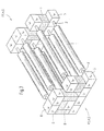
Figuren 2 bis 4: - schematische, perspektivische Darstellungen von Ausführungsvarianten des erfindungsgemäßen modulartigen Aufbaues.
- FIG. 1 :
- in a schematic representation of a longitudinal section through the inventive, drive-side end of a roll of a paper machine.
- FIGS. 2 to 4:
- schematic, perspective representations of embodiments of the module-like structure according to the invention.
In den Figuren wurden für gleiche Bauteile auch gleiche Positionszahlen verwendet.
-
Figur 1 - zeigt ein stirnseitiges Ende des Antriebes einer
Walze 1, die im Beispiel ein, Trockenzylinder sein soll, im Nachfolgenden aber weiterhin als Walze bezeichnet wird.
- FIG. 1
- shows a front end of the drive of a
roller 1, which should be a drying cylinder in the example, but will continue to be referred to as a roller in the following.
Im rechten Bildteil ist das stirnseitige eine Ende der Walze 1 noch mit dargestellt. Die Walze 1 ist mit einem Wellenzapfen 2 versehen, die ein Wälzlager 3 für die Walze 1 aufnimmt.In the right part of the image, the front end one end of the
Am zur Walze 1 abgewandten Ende des Wellenzapfens 2 befindet sich ein Motor 4 für den Antrieb der Walze.At the end facing away from the
Im Beispiel dafür wurde zweckmäßigerweise ein sogenannter Aufsteckmotor mit Hohlwelle verwendet. Dieser Motor ist ein Drehstrom- Asynchronmotor mit hoher Polpaarzahl (>12).In the example of this, a so-called plug-on motor with a hollow shaft was expediently used. This motor is a three-phase asynchronous motor with a high number of pole pairs (> 12).
Da dieser Motor scheibenartig aufgebaut und daher sehr schmal ist, ist der benötigte Platzbedarf in axialer Richtung nur sehr gering. Außerdem kann so problemlos auch ein oder noch mehrere solcher Motoren aufgesteckt werden, wenn die Walze mit unterschiedlichen Drehzahlen gefahren werden soll.Since this engine has a disc-like design and therefore is very narrow, the space required in the axial direction is only very small. In addition, so easily one or more such motors can be plugged when the roller is to be driven at different speeds.
Das Lager 3 sowie der Motor (gegebenenfalls weitere Motoren) 4 sind im gewählten Beispiel von einem quaderförmigen Gehäuse 5 mit Kantenlängen Länge (L) x Breite (B) x Höhe (H) ∼ 400 bis 500 x 1500 x 1000 bis 2000 mm umgeben.The bearing 3 and the motor (possibly other motors) 4 are surrounded in the example chosen by a
Das Gehäuse besteht vorzugsweise aus dem Werkstoff Stahl, dessen Einzelteile sich gut miteinander verschweißen lassen.The housing is preferably made of the material steel, whose individual parts can be welded together well.
Selbstverständlich wären auch andere geometrische Formen, wie Gehäuse mit dreieckigem, parallelogrammförmigen, trapezförmigen oder quadratischem Querschnitt denkbar, weil diese Formen sich leicht fertigen und auch für den gewünschten Zweck gut zusammenbauen lassen.Of course, other geometric shapes, such as housing with triangular, parallelogram, trapezoidal or square cross-section would be conceivable because these shapes can be easily manufactured and assemble well for the desired purpose.
Aus der Figur ist entnehmbar, dass das rechteckige Gehäuse aus zwei Teilen, Teil 5a und Teil 5b gefertigt ist.From the figure it can be seen that the rectangular housing is made of two parts, part 5a and
Das hat zum einen Vorteile bei der Fertigung des Gehäuses selbst, aber vor allem ist die Demontage dadurch einfacher bei Wartungsarbeiten zu realisieren. Der Teil 5a überdeckt das Lager 3 und der Teil 5b den Motor.This has advantages in the production of the housing itself, but above all is this makes dismantling easier during maintenance. The part 5a covers the bearing 3 and the
Aus der Figur 1 ist ein dem Gehäuse 5 in Größe und Form adäquates, paralleles Zwischenstück 7. welches ebenfalls wie das Gehäuse 5 Teil eines Baukastensystems ist, entnehmbar.From Figure 1 is a
Dieses Zwischenstück 7 ist in der Figur 1 unterhalb des Gehäuses 5 dargestellt und oberhalb sowie seitlich des Gehäuses 5 nur angedeutet. Das Zwischenstück 7 ist an einer parallelen Anschlußfläche 8 mit dem Gehäuse 5 bzw. 5a und 5b kraftschlüssig, z.B. durch Verschweißen verbunden. Auf Grund dieser einfach herstellbaren und stapelbaren - hier kastenförmigen Ausführung - ist es möglich, mehrere Motoreinheiten modulartig in gewünschtem Maße beliebig übereinander und nebeneinander aufzubauen, so dass sich insgesamt eine tragende ortsfeste Abstützung A der Bauteile innerhalb der Maschine ergibt. Damit lässt sich sogar eine stabile Stuhlung S der Maschine bilden oder diese auf zweckmäßige Weise ergänzen. In der Figur 1 sind die gebildeten oder bereits bestehenden Stuhlungsteile mit Position S gekennzeichnet.This
Das so geschaffene Modul hat den Vorteil, dass nunmehr kleinere Rastermaße als sie bisher für die Stuhlung S nötig waren, möglich sind.The module thus created has the advantage that now smaller pitches than they were previously necessary for the chair S, are possible.
Aus den Figuren 2 bis 4 sind Ausführungsvarianten der Bildung der vorstehend genannten Module schematisch grob dargestellt. So zeigt Figur 2 ein Walzenpaar, das beispielsweise ein Glättwerk, ein Presswalzen- oder Speedsizer-/-Coater-Paar sein kann.From the figures 2 to 4 embodiments of the formation of the above-mentioned modules are shown schematically coarse. Thus, Figure 2 shows a pair of rollers, which may be, for example, a calender, a press roll or Speedsizer - / - coater pair.
Hierbei sind Gehäuse 5 und ein Zwischenstück 7 übereinander angeordnet.In this case,
In der Figur 3 ist ein Walzenpaket bzw. eine Schaar von Walzen dargestellt, welche Leitwalzen, oder Trockenzylinder sein können. Die Motorengehäuse 5 und die Zwischenstücke 7 sind hierbei übereinander und nebeneinander immer jeweils an den parallelen Anschlußflächen 8 miteinander verbunden. FIG. 3 shows a roll pack or rolls of rolls, which may be guide rolls or drying cylinders. The
Schließlich stellt die Figur 4 eine weitere mögliche Variante in Form eines Walzenpaketes mit schräg, treppenartig aufsteigend angeordneten Motorgehäusen 5 dar, wie sie bei einem Kalander aufgebaut sein können.Finally, Figure 4 illustrates the figure, a further possible variant in the form of a roll stack with inclined, ascending stair-like arranged
Bei den Figuren 3 und 4 bilden die Gehäuse und Zwischenräume gleichzeitig die Stuhlung S der Maschine.In the figures 3 and 4 , the housing and spaces at the same time form the stiffening S of the machine.
Man erkennt aus den Figuren 2 bis 4, die Gleichartigkeit der gebildeten Stuhlung S, das heißt der ortsfesten Abstützung A auf Trieb (TS)- und Führerseite (FS) der Maschine.It can be seen from Figures 2 to 4, the similarity of the formed stiffening S, that is, the stationary support A on drive (TS) - and leader (FS) of the machine.
Die erfindungsgemäße Antriebseinheit kommt mit weniger und einfacher gestalteten sowie kleiner dimensionierten Bauteilen-auch der Antriebsmotoren-aus, was besonders vorteilhaft im Hinblick auf die Kosten für Konstruktion, Bau, Transport und Lagerhaltung ist.The drive unit according to the invention comes with less and simpler designed and smaller sized components-including the drive motors-out, which is particularly advantageous in terms of the cost of construction, construction, transportation and storage.
In der Wandung des Gehäuses 5 sind Bohrungen 6 vorhanden, durch die verschiedene Leitungen mit Kühlfluid und Schmiermittel in das Innere des Gehäuses 5 gelangen können.In the wall of the
Claims (11)
- Drive unit for rotating components such as rollers and cylinders of a machine for producing and/or processing a continuous material strip made in particular from paper or cardboard, whereina) the rotating components (1) have bearing journals (2) at in each case at least one of their end-side endsb) the end-side bearing journals (2) hold in each case a separate drive motor (4)c) the respective component (1) and the drive motor (4) are supported together in a positionally fixed manner,d) a housing (5) is provided which surrounds both the drive motor (4) and also the bearing (3) of the respective component (1),
characterized in thate) the respective housing (5) has a cross section, which extends over its entire length, with at least one connecting face (8) andf) the respective housing (5) is designed such that it can be assembled in a modular fashion together with at least one further housing (5), and with at least one intermediate piece (7) between the connecting faces (8) of the respective housing (5), for positionally fixed support (A). - Drive unit according to Claim 1,
characterized in that
the cross section of the respective housing (5) is of polygonal design. - Drive unit according to Claim 1 or 2,
characterized in that
the intermediate piece (7) is designed appropriately with respect to the housing (5). - Drive unit according to one or more of Claims 1 to 3,
characterized in that
each housing (5) and each intermediate piece (7) is of cuboid-shaped, prism-shaped or parallelogramepiped-shaped design and is composed of the material steel. - Drive unit according to one or more of the preceding claims,
characterized in that
the respective housing (5) is provided with bores (6) for conveying through a cooling fluid. - Drive unit according to one or more of the preceding claims,
characterized in that
each housing (5) and each intermediate piece (7) has dimensions which correspond approximately to the relationship: length : width ∼ height : with = 1 : 2 to 1 : 3, wherein different installation sizes can be selected. - Drive unit according to one or more of the preceding claims,
characterized in that
the drive motor (4) and a bearing (3) for the component (1) which is to be driven are accommodated in the respective housing (5), with the drive motor being arranged at the outer end of the bearing journal (2). - Drive unit according to one or more of the preceding claims,
characterized in that
the respective housing (5) and the respective intermediate piece (7) are connected to one another in a force-fitting manner in the region of their at least one connecting face (8). - Drive unit according to one or more of the preceding claims,
characterized in that
the respective housing (5) is of split design, composed of the parts (5a and 5b). - Drive unit according to one or more of claims 1 to 9,
characterized in that
the positionally fixed support, which is of modular design, can be integrated into a provided frame (S) of the machine for producing and/or processing a continuous material strip, or forms said frame (S) itself. - Drive unit according to one or more of the preceding claims,
characterized in that
the electric drive motor (4) is a plug-on hollow-shaft three-phase asynchronous motor, as is known per se.
Applications Claiming Priority (5)
| Application Number | Priority Date | Filing Date | Title |
|---|---|---|---|
| DE2000125316 DE10025316A1 (en) | 2000-05-22 | 2000-05-22 | Drive unit is for rotating paper and board machine parts |
| DE10025316 | 2000-05-22 | ||
| DE10035578 | 2000-07-21 | ||
| DE2000135578 DE10035578B4 (en) | 2000-07-21 | 2000-07-21 | drive unit |
| EP01110935A EP1158188B1 (en) | 2000-05-22 | 2001-05-05 | Driving unit |
Related Parent Applications (1)
| Application Number | Title | Priority Date | Filing Date |
|---|---|---|---|
| EP01110935A Division EP1158188B1 (en) | 2000-05-22 | 2001-05-05 | Driving unit |
Publications (3)
| Publication Number | Publication Date |
|---|---|
| EP1437516A2 EP1437516A2 (en) | 2004-07-14 |
| EP1437516A3 EP1437516A3 (en) | 2005-11-16 |
| EP1437516B1 true EP1437516B1 (en) | 2007-11-07 |
Family
ID=26005783
Family Applications (2)
| Application Number | Title | Priority Date | Filing Date |
|---|---|---|---|
| EP01110935A Expired - Lifetime EP1158188B1 (en) | 2000-05-22 | 2001-05-05 | Driving unit |
| EP04100531A Expired - Lifetime EP1437516B1 (en) | 2000-05-22 | 2001-05-05 | Driving unit |
Family Applications Before (1)
| Application Number | Title | Priority Date | Filing Date |
|---|---|---|---|
| EP01110935A Expired - Lifetime EP1158188B1 (en) | 2000-05-22 | 2001-05-05 | Driving unit |
Country Status (3)
| Country | Link |
|---|---|
| EP (2) | EP1158188B1 (en) |
| AT (2) | ATE377715T1 (en) |
| DE (2) | DE50113243D1 (en) |
Families Citing this family (12)
| Publication number | Priority date | Publication date | Assignee | Title |
|---|---|---|---|---|
| WO2003080927A1 (en) * | 2002-03-24 | 2003-10-02 | Vomag Gmbh | Device for supporting a shaft |
| DE102004001467A1 (en) * | 2003-03-19 | 2004-10-21 | Voith Paper Patent Gmbh | Machine or machine section with at least one electric motor, which is preferably designed as a synchronous motor and / or slip-on motor and is used for the direct drive of a winding core of a winding roll or for the direct drive of another rotary component, in particular for use in the paper industry, and a conversion method relating thereto |
| EP1787929A1 (en) * | 2003-03-19 | 2007-05-23 | Voith Patent GmbH | Machine or machine section with at least one electric motor, preferably as a synchronous motor and/or shaft mounted and used for direct driving a core of a winding reel or for the direct drive of another swivel component, in particular for application in the paper industry and the relevant conversion method |
| DE10339733A1 (en) * | 2003-08-28 | 2004-11-25 | Siemens Ag | Drive for roller esp. heavy rollers is connected directly and mechanically rigid to rotor of electric motor, and motor stator connected mechanically elastic to machine bed or roller frame |
| DE102004013781A1 (en) * | 2004-03-20 | 2005-10-06 | Voith Paper Patent Gmbh | Cable drive device |
| DE102004059402A1 (en) * | 2004-12-09 | 2006-06-14 | Voith Paper Patent Gmbh | Modular machine for the production and / or treatment or / and handling of a moving material web, in particular of paper or cardboard |
| DE102005000116A1 (en) * | 2005-09-14 | 2007-03-15 | Voith Patent Gmbh | Material web e.g. paper web, winding machine e.g. double bearing roller winding machine, has roller with bearing pins and driven by drive device that is directly connected or screwed with machine, where drive device has hollow shaft motor |
| PT1979536T (en) * | 2006-01-25 | 2017-06-15 | Georgia Pacific Consumer Products Lp | Machine for the production of a fiber web |
| DE102006011632A1 (en) * | 2006-03-14 | 2007-09-20 | Voith Patent Gmbh | Drive assembly for driving a roller |
| DE102009000745A1 (en) * | 2009-02-10 | 2010-08-12 | Voith Patent Gmbh | drive unit |
| DE102009003747A1 (en) * | 2009-04-06 | 2010-10-07 | As-Antriebstechnik Und Service Gmbh | torque arm |
| IT202100012893A1 (en) * | 2021-05-19 | 2022-11-19 | V Project S R L | MACHINE FOR GRINDING FOOD PRODUCTS |
Family Cites Families (6)
| Publication number | Priority date | Publication date | Assignee | Title |
|---|---|---|---|---|
| US1909792A (en) * | 1932-07-28 | 1933-05-16 | Milton T Weston | Variable speed drive |
| CH587690A5 (en) * | 1975-01-29 | 1977-05-13 | Escher Wyss Ag | |
| DE3409738A1 (en) * | 1984-03-15 | 1985-09-26 | Mannesmann AG, 4000 Düsseldorf | TRANSPORT UNIT FOR LONG-EXTENDED, METALLIC HOT MATERIAL |
| DE8703410U1 (en) * | 1987-03-06 | 1987-05-21 | J.M. Voith Gmbh, 7920 Heidenheim, De | |
| FI80304C (en) * | 1989-01-23 | 1990-05-10 | Katsa Oy | Arrangement for control gear |
| FI950176A0 (en) * | 1995-01-16 | 1995-01-16 | Tasowheel Oy | Anordning Foer spelfri ledning and maetning av till en ventil ledd roerelse |
-
2001
- 2001-05-05 AT AT04100531T patent/ATE377715T1/en not_active IP Right Cessation
- 2001-05-05 EP EP01110935A patent/EP1158188B1/en not_active Expired - Lifetime
- 2001-05-05 DE DE50113243T patent/DE50113243D1/en not_active Expired - Fee Related
- 2001-05-05 EP EP04100531A patent/EP1437516B1/en not_active Expired - Lifetime
- 2001-05-05 AT AT01110935T patent/ATE338893T1/en not_active IP Right Cessation
- 2001-05-05 DE DE50110919T patent/DE50110919D1/en not_active Expired - Fee Related
Also Published As
| Publication number | Publication date |
|---|---|
| ATE377715T1 (en) | 2007-11-15 |
| EP1437516A3 (en) | 2005-11-16 |
| EP1158188A1 (en) | 2001-11-28 |
| DE50110919D1 (en) | 2006-10-19 |
| ATE338893T1 (en) | 2006-09-15 |
| DE50113243D1 (en) | 2007-12-20 |
| EP1437516A2 (en) | 2004-07-14 |
| EP1158188B1 (en) | 2006-09-06 |
Similar Documents
| Publication | Publication Date | Title |
|---|---|---|
| EP0741020B2 (en) | Rotary printing machine having a free mountable folding apparatus | |
| EP0741019B2 (en) | Individually driven folding apparatus for a rotary printing machine | |
| EP1437516B1 (en) | Driving unit | |
| DE4225380A1 (en) | Hydrostatic unit with a main pump and a secondary pump | |
| DE10015340C2 (en) | Roll stand for rolling mills for rolling metallic pipes, bars or wires | |
| DE202019103771U1 (en) | Double gear, in particular for an electromotive drive train, with a support structure and associated bearing glasses | |
| DE10025316A1 (en) | Drive unit is for rotating paper and board machine parts | |
| DE19530283A1 (en) | Transfer cylinder with electromotive drive unit | |
| DE1945346C3 (en) | Intermediate layer for a folded filter and device for their production | |
| DE2119389A1 (en) | Modular system for the construction of any column arrangements of roll machines, especially calenders | |
| DE2847587A1 (en) | TRANSMISSION | |
| DE3644628A1 (en) | ROLLING MACHINE FOR COLD BENDING PROFILES | |
| DE19510721C1 (en) | Angled rolling device for tubes or rods | |
| DE20023897U1 (en) | Drive unit for a rotating part comprises a housing that surrounds a motor and journal bearing and has connecting surfaces suitable for mounting in a modular manner | |
| DE3517975C2 (en) | ||
| DE69814908T2 (en) | CAROUSEL WRAP ROLL | |
| DE3231590A1 (en) | MECHANICAL DRIVE DEVICE IN THE DRYING SECTION OF A PAPER MACHINE | |
| DE19616791A1 (en) | Rolling block for rolling wire, bars, tubes or flat metallic rolled material | |
| DE2924255C2 (en) | Drive device with electric motor for a roll shell, in particular a calender roll | |
| DE1602193A1 (en) | Roll changing device on a combined horizontal and vertical stand | |
| DE2833456A1 (en) | Tube stretch-reducing mill train - has only intermediate rolling stands fitted with separate differential gear unit | |
| WO2001015875A1 (en) | Machine for crosscutting webs of material | |
| EP2955821A1 (en) | Drive device for a rotatable element | |
| DE1563007A1 (en) | Two-pole inductor for electrical machines | |
| EP0924338A2 (en) | Drive unit with a moving torque support for rolls |
Legal Events
| Date | Code | Title | Description |
|---|---|---|---|
| PUAI | Public reference made under article 153(3) epc to a published international application that has entered the european phase |
Free format text: ORIGINAL CODE: 0009012 |
|
| AC | Divisional application: reference to earlier application |
Ref document number: 1158188 Country of ref document: EP Kind code of ref document: P |
|
| AK | Designated contracting states |
Kind code of ref document: A2 Designated state(s): AT DE FI SE |
|
| PUAL | Search report despatched |
Free format text: ORIGINAL CODE: 0009013 |
|
| AK | Designated contracting states |
Kind code of ref document: A3 Designated state(s): AT DE FI SE |
|
| 17P | Request for examination filed |
Effective date: 20060516 |
|
| AKX | Designation fees paid |
Designated state(s): AT DE FI SE |
|
| RAP1 | Party data changed (applicant data changed or rights of an application transferred) |
Owner name: VOITH PATENT GMBH |
|
| GRAP | Despatch of communication of intention to grant a patent |
Free format text: ORIGINAL CODE: EPIDOSNIGR1 |
|
| GRAS | Grant fee paid |
Free format text: ORIGINAL CODE: EPIDOSNIGR3 |
|
| GRAA | (expected) grant |
Free format text: ORIGINAL CODE: 0009210 |
|
| AC | Divisional application: reference to earlier application |
Ref document number: 1158188 Country of ref document: EP Kind code of ref document: P |
|
| AK | Designated contracting states |
Kind code of ref document: B1 Designated state(s): AT DE FI SE |
|
| REF | Corresponds to: |
Ref document number: 50113243 Country of ref document: DE Date of ref document: 20071220 Kind code of ref document: P |
|
| REG | Reference to a national code |
Ref country code: SE Ref legal event code: TRGR |
|
| PLBE | No opposition filed within time limit |
Free format text: ORIGINAL CODE: 0009261 |
|
| STAA | Information on the status of an ep patent application or granted ep patent |
Free format text: STATUS: NO OPPOSITION FILED WITHIN TIME LIMIT |
|
| 26N | No opposition filed |
Effective date: 20080808 |
|
| PGFP | Annual fee paid to national office [announced via postgrant information from national office to epo] |
Ref country code: AT Payment date: 20090515 Year of fee payment: 9 Ref country code: DE Payment date: 20090525 Year of fee payment: 9 Ref country code: FI Payment date: 20090515 Year of fee payment: 9 Ref country code: SE Payment date: 20090514 Year of fee payment: 9 |
|
| PG25 | Lapsed in a contracting state [announced via postgrant information from national office to epo] |
Ref country code: AT Free format text: LAPSE BECAUSE OF NON-PAYMENT OF DUE FEES Effective date: 20100505 Ref country code: FI Free format text: LAPSE BECAUSE OF NON-PAYMENT OF DUE FEES Effective date: 20100505 |
|
| EUG | Se: european patent has lapsed | ||
| PG25 | Lapsed in a contracting state [announced via postgrant information from national office to epo] |
Ref country code: SE Free format text: LAPSE BECAUSE OF NON-PAYMENT OF DUE FEES Effective date: 20100506 |
|
| PG25 | Lapsed in a contracting state [announced via postgrant information from national office to epo] |
Ref country code: DE Free format text: LAPSE BECAUSE OF NON-PAYMENT OF DUE FEES Effective date: 20101201 |