EP1435550A1 - Robot control apparatus, robot, and production facility - Google Patents
Robot control apparatus, robot, and production facility Download PDFInfo
- Publication number
- EP1435550A1 EP1435550A1 EP02768130A EP02768130A EP1435550A1 EP 1435550 A1 EP1435550 A1 EP 1435550A1 EP 02768130 A EP02768130 A EP 02768130A EP 02768130 A EP02768130 A EP 02768130A EP 1435550 A1 EP1435550 A1 EP 1435550A1
- Authority
- EP
- European Patent Office
- Prior art keywords
- section
- robot
- dedicated
- input
- display unit
- Prior art date
- Legal status (The legal status is an assumption and is not a legal conclusion. Google has not performed a legal analysis and makes no representation as to the accuracy of the status listed.)
- Withdrawn
Links
Images



Classifications
-
- G—PHYSICS
- G05—CONTROLLING; REGULATING
- G05B—CONTROL OR REGULATING SYSTEMS IN GENERAL; FUNCTIONAL ELEMENTS OF SUCH SYSTEMS; MONITORING OR TESTING ARRANGEMENTS FOR SUCH SYSTEMS OR ELEMENTS
- G05B19/00—Program-control systems
- G05B19/02—Program-control systems electric
- G05B19/418—Total factory control, i.e. centrally controlling a plurality of machines, e.g. direct or distributed numerical control [DNC], flexible manufacturing systems [FMS], integrated manufacturing systems [IMS] or computer integrated manufacturing [CIM]
- G05B19/41815—Total factory control, i.e. centrally controlling a plurality of machines, e.g. direct or distributed numerical control [DNC], flexible manufacturing systems [FMS], integrated manufacturing systems [IMS] or computer integrated manufacturing [CIM] characterised by the cooperation between machine tools, manipulators and conveyor or other workpiece supply system, workcell
-
- G—PHYSICS
- G05—CONTROLLING; REGULATING
- G05B—CONTROL OR REGULATING SYSTEMS IN GENERAL; FUNCTIONAL ELEMENTS OF SUCH SYSTEMS; MONITORING OR TESTING ARRANGEMENTS FOR SUCH SYSTEMS OR ELEMENTS
- G05B2219/00—Program-control systems
- G05B2219/20—Pc systems
- G05B2219/22—Pc multi processor system
- G05B2219/2207—Microcontroller combined with state sequencer
-
- G—PHYSICS
- G05—CONTROLLING; REGULATING
- G05B—CONTROL OR REGULATING SYSTEMS IN GENERAL; FUNCTIONAL ELEMENTS OF SUCH SYSTEMS; MONITORING OR TESTING ARRANGEMENTS FOR SUCH SYSTEMS OR ELEMENTS
- G05B2219/00—Program-control systems
- G05B2219/30—Nc systems
- G05B2219/39—Robotics, robotics to robotics hand
- G05B2219/39105—Manipulator cooperates with moving machine, like press brake
-
- Y—GENERAL TAGGING OF NEW TECHNOLOGICAL DEVELOPMENTS; GENERAL TAGGING OF CROSS-SECTIONAL TECHNOLOGIES SPANNING OVER SEVERAL SECTIONS OF THE IPC; TECHNICAL SUBJECTS COVERED BY FORMER USPC CROSS-REFERENCE ART COLLECTIONS [XRACs] AND DIGESTS
- Y02—TECHNOLOGIES OR APPLICATIONS FOR MITIGATION OR ADAPTATION AGAINST CLIMATE CHANGE
- Y02P—CLIMATE CHANGE MITIGATION TECHNOLOGIES IN THE PRODUCTION OR PROCESSING OF GOODS
- Y02P90/00—Enabling technologies with a potential contribution to greenhouse gas [GHG] emissions mitigation
- Y02P90/02—Total factory control, e.g. smart factories, flexible manufacturing systems [FMS] or integrated manufacturing systems [IMS]
Definitions
- the present invention relates to a robot control apparatus, a robot and production facilities.
- a robot is seldom used alone in the practical industrial application. Normally, it is equipped with, for example, a jig for handling works, or a device for transportation, welding, etc., or other types of tools such as a torch, and performs a certain specific task such as machining processing, welding, etc. in a series of production activities. For example, in a series of production activities, a conveyor carries a work to a place to be machined there and then to other place for welding.
- a robot control apparatus gathers data which represents operating status of peripheral devices, via an input-output section of sequence controller.
- FIG. 6 is a block diagram, showing an exemplary structure of conventional robot control apparatus.
- robot control apparatus 52 comprises a robot arm control unit 53 and sequence controller 55.
- Robot arm control unit 53 and sequence controller 55 exchange signals to each other via bus 58.
- Robot arm control unit 53 controls robot main body 51.
- Sequence controller 55 controls peripheral devices 54 working in collaboration with robot main body 51.
- Sequence controller 55 includes control section 57 and input-output section 56.
- Control section 57 exchanges signals with robot arm control unit 53 via bus 58.
- Input-output section 56 receives from peripheral devices 54 signals that represent a state of operation being carried out by peripheral devices 54. Input-output section 56 also outputs and delivers control signals to peripheral devices 54 in accordance with state of operation being performed by robot main body 51.
- Control section 57 processes signals from peripheral devices 54 and signals from robot arm control unit 53, and controls input-output section 56 and peripheral devices 54.
- Input-output section 56 here performs a signal processing in accordance with an input-output mode of peripheral device 54.
- the input-output section of sequence controller is compelled to change the output mode to be compatible with respective input-output modes of peripheral devices, if the peripheral devices constituting a robot control system have different input-output modes.
- the constituent peripheral devices when constituting a robot control system, the constituent peripheral devices have to be selected among those which have the same mode of input-output compatible with sequence controller; or, an appropriate sequence controller needs to be provided after confirming the input-output modes of respective peripheral devices.
- the present invention aims to offer a robot control apparatus.
- the present robot control apparatus When structuring a robot control system using a robot and peripheral devices, the present robot control apparatus lessens limitations due to difference in the input-output mode at the apparatus and helps constituting a flexible system. Furthermore, the present robot control apparatus enables to constitute robot control systems with ease by simply applying a minor modification on the robot control apparatus.
- the present robot control apparatus contains a robot arm control unit for controlling action of a robot arm and a sequence controller for controlling an apparatus other than the robot arm.
- the sequence controller comprises a control section for outputting control signals for controlling action of the apparatus and an input-output section for delivering the signals to the apparatus.
- the input-output section comprises a dedicated section and a common processing section for sending signals to the dedicated section.
- the dedicated section is provided detachable to the common processing section, and outputs signal in accordance with a predetermined output mode.
- the above-configured robot control apparatus in the present invention is capable of complying with the input-output modes of respective peripheral devices even in a system formed of various peripheral devices having different input-output modes.
- a robot control apparatus in the present invention further comprises a display unit coupled therewith, and the dedicated section is provided with a recognition unit which identifies a predetermined input-output mode. An operator can confirm, through the display unit, a relevant input-output mode of a dedicated section being connected with a certain peripheral device. Whether or not the connection is correct can also be confirmed easily.
- a robot control apparatus in the present invention having the above configuration is further provided with an input section in the display unit.
- the input section includes a selector for selecting a certain dedicated section to be used among a plurality of dedicated sections connected.
- a dedicated section compatible with the input-output mode of a peripheral device can be selected through the selector of display unit.
- a robot control apparatus in the present invention can be used also for a robot which has a robot main body provided with a robot arm.
- a robot containing a robot control apparatus in the present invention can be used on a production facility which contains, for example, machining and welding process steps.
- FIG. 1 is a block diagram showing a robot control system formed of a robot, a robot control apparatus and peripheral devices of the robot.
- robot control apparatus 2 comprises robot arm control unit 3 and sequence controller 5.
- Robot arm control unit 3 controls robot main body 1.
- Robot main body 1 includes robot arm 101 and a robot arm driving unit (not shown).
- Sequence controller 5 controls peripheral devices 4 working in collaboration with robot main body 1.
- Robot arm control unit 3 and sequence controller 5 exchange signals via bus 20.
- Sequence controller 5 includes input-output section 6 and control section 7.
- Control section 7 transmits and receives signals to and from robot arm control unit 53 via bus 20.
- Input-output section 6 receives a signal representing the operating status from peripheral device 54, and outputs control signal to peripheral device 4 in accordance with operating status of robot main body 1.
- Control section 7 processes signal from peripheral device 4 and signal from robot arm control unit 3, and controls input-output section 6 and peripheral device 4. Control section 7 also reads a program for operating the peripheral devices, and outputs control signal to control operation of peripheral devices.
- Control section 7 and input-output section 6 exchange signals via bus 21.
- Input-output section 6 includes dedicated section 8 and common processing section 9.
- Dedicated section 8 handles the input-output of signals in line with the input-output mode of peripheral device 4.
- Common processing section 9 processes information delivered from control section 7 and signal arriving from dedicated section 8.
- dedicated section 8 is provided detachable to common processing section 9.
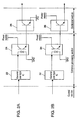
- an output of general use logic IC 22 is led to the anode of a photo diode in photo coupler 24, and the cathode is connected to a ground (GND).
- the collector of photo transistor in photo coupler 24 is connected to a power source, and the emitter is led to the base of transistor 26.
- the collector of transistor 26 is treated as the output portion to the outside, while the emitter is connected to the frame GND (FG).
- output of general use logic IC 32 is led to the anode of a photo diode in photo coupler 34, and the cathode is connected to the ground (GND), in the same way as in FIG. 2A.
- the collector of photo transistor in photo coupler 34 is connected to power source, and the emitter is led to the base of transistor 34.
- the collector of transistor is connected to power source, and the emitter is treated as output portion to the outside.
- control section 7 a region before the stage of general use logic 22, 23, which region delivering signals to general use logic IC 22, 32, is included in control section 7.
- a region starting from general use logic IC 22, 32, ending at photo couplers 24, 34 are included in common processing section 9.
- a region of transistor 26, 36 and thereafter is included in dedicated section 8.
- an output mode can be modified by only changing dedicated section 8 (or, transistor 26, 36, in the above-described practical example).
- FIG. 3 and FIG. 4 A second exemplary embodiment of the present invention is described referring to FIG. 3 and FIG. 4. Those portions having the same structure as that of the first embodiment are represented by using the same reference numerals, and the description on which portions are omitted.
- dedicated section 8 is further provided with recognition unit 10.
- Information recognized at recognition unit 10 is delivered to common processing section 9.
- the information recognized at recognition unit 10 is delivered also to display unit 11 by way of control section 7, bus line 20 and robot arm control unit 3.
- recognition unit 10 is described.
- values representing respective input-output modes corresponding to dedicated sections are preset at DIP switch 40, or the like other means.
- the preset values are read out to be stored in control section 7 via common processing section 9 and data bus 21.
- Data corresponding to a preset value is sent from robot arm control unit 3 to display unit 11 via data bus 20.
- the data delivered from common processing section 9 may either be parallel or serial.
- control section 7 delivers data of an input-output mode that corresponds to a preset value at DIP switch 40 to display unit 11 to be displayed thereon.
- display unit 11 can display an input-output mode of a dedicated section.
- a preset value at DIP switch, or at the like means may further indicate, not only the input-output mode of peripheral device, but a state of peripheral devices connection or types of the peripheral devices, etc.
- a dedicated section when a dedicated section is connected with common processing section during an operation of coupling a robot control apparatus with peripheral devices, an operator can confirm on the display unit the input-output mode of the relevant dedicated section being connected to a peripheral device.
- the display unit also facilitates an easy confirmation that connection of a dedicated section is correct.
- a third exemplary embodiment of the present invention is described with reference to FIG. 5. Those portions having the same structure as that of the first embodiment and the second embodiment are represented by using the same reference numerals, and the description on which portions are omitted.
- input-output section 6 is provided with a plurality of dedicated sections 8.
- the plurality of dedicated sections 8 is connected to a common processing section 9.
- Respective dedicated sections 8 in the present embodiment contain recognition unit 10 shown in FIG. 3.
- dedicated section 8 is shown for two units in FIG. 5, it may be provided for a plurality more than two.
- Display unit 11 includes input section 12 for used by an operator.
- the switching at common processing section 9 can be carried out with ease by making use of a general use logic IC.
- control section 7 sends a switching signal to common processing section 9 via bus 21, in response to a signal delivered from input section 12 telling to select dedicated section 8.
- common processing section 9 a connection between a dedicated section, which inputs/outputs signals of control section 7 for controlling peripheral device 4, and control section 7 is switched by means of a selector which is one of general use logic ICs.
- dedicated section 8 that fits to specific input-output mode of peripheral device 4 is selected from among a plurality of dedicated sections 8 connected with common processing section 5, in accordance with instruction delivered from input section 12 of display unit 11.
- Each of the plurality of dedicated sections may be provided with a symbol and the like for recognizing which section is used, so that input section 12 of display unit 11 can select a suitable dedicated section.
- Robot control apparatus described in the above embodiments can be used for a robot including the robot main body having a robot arm.
- a robot containing a robot control apparatus in the above-described embodiment can be used in a production facility which includes a machining process, an welding and the like process steps.
- a robot control apparatus in the present invention can comply with different input-output modes of peripheral devices with less adapting operation. And modifying operation can be implemented easily.
- a display unit facilitates an easy recognition of input-output modes, connection status, as well as kinds and relevant information regarding the peripheral devices.
Landscapes
- Engineering & Computer Science (AREA)
- General Engineering & Computer Science (AREA)
- Manufacturing & Machinery (AREA)
- Quality & Reliability (AREA)
- Physics & Mathematics (AREA)
- General Physics & Mathematics (AREA)
- Automation & Control Theory (AREA)
- Numerical Control (AREA)
- Manipulator (AREA)
Abstract
A robot control apparatus, with which the limitation due to difference
in the input-output mode of peripheral devices is lessened and a robot control
system can be structured flexibly. The present robot control apparatus
includes a robot arm control unit for controlling action of a robot arm and a
sequence controller for controlling an apparatus other than the robot arm.
The sequence controller comprises a control section for outputting signals for
controlling operation of the apparatus and an input-output section for
delivering the signals to the apparatus. The input-output section comprises
a dedicated section and a common processing section which transfers signals
to the dedicated section. The dedicated section is disposed detachable to the
common processing section, and outputs a signal in accordance with a
predetermined output mode. Thus the present robot control apparatus can
comply with different input-output modes of peripheral facilities forming a
robot control system.
Description
The present invention relates to a robot control apparatus, a robot and
production facilities.
A robot is seldom used alone in the practical industrial application.
Normally, it is equipped with, for example, a jig for handling works, or a
device for transportation, welding, etc., or other types of tools such as a torch,
and performs a certain specific task such as machining processing, welding,
etc. in a series of production activities. For example, in a series of production
activities, a conveyor carries a work to a place to be machined there and then
to other place for welding.
In a production process as described above, in order to recognize state
of operations being performed by peripheral devices a robot control apparatus
gathers data which represents operating status of peripheral devices, via an
input-output section of sequence controller.
Now in the following, an input-output section of a conventional robot
control system formed of a robot control apparatus and a sequence controller
is described.
FIG. 6 is a block diagram, showing an exemplary structure of
conventional robot control apparatus.
Referring to FIG. 6, robot control apparatus 52 comprises a robot arm
control unit 53 and sequence controller 55. Robot arm control unit 53 and
sequence controller 55 exchange signals to each other via bus 58.
Robot arm control unit 53 controls robot main body 51.
Input-output section 56 receives from peripheral devices 54 signals
that represent a state of operation being carried out by peripheral devices 54.
Input-output section 56 also outputs and delivers control signals to peripheral
devices 54 in accordance with state of operation being performed by robot
main body 51.
Input-output section 56 here performs a signal processing in
accordance with an input-output mode of peripheral device 54.
In an exemplary case of conventional robot control apparatus as
described above, the input-output section of sequence controller is compelled
to change the output mode to be compatible with respective input-output
modes of peripheral devices, if the peripheral devices constituting a robot
control system have different input-output modes.
In other words, when constituting a robot control system, the
constituent peripheral devices have to be selected among those which have the
same mode of input-output compatible with sequence controller; or, an
appropriate sequence controller needs to be provided after confirming the
input-output modes of respective peripheral devices.
The present invention aims to offer a robot control apparatus.
When structuring a robot control system using a robot and peripheral
devices, the present robot control apparatus lessens limitations due to
difference in the input-output mode at the apparatus and helps constituting a
flexible system. Furthermore, the present robot control apparatus enables to
constitute robot control systems with ease by simply applying a minor
modification on the robot control apparatus. The present robot control
apparatus contains a robot arm control unit for controlling action of a robot
arm and a sequence controller for controlling an apparatus other than the
robot arm.
The sequence controller comprises a control section for outputting
control signals for controlling action of the apparatus and an input-output
section for delivering the signals to the apparatus.
The input-output section comprises a dedicated section and a common
processing section for sending signals to the dedicated section. The dedicated
section is provided detachable to the common processing section, and outputs
signal in accordance with a predetermined output mode.
The above-configured robot control apparatus in the present invention
is capable of complying with the input-output modes of respective peripheral
devices even in a system formed of various peripheral devices having different
input-output modes.
A robot control apparatus in the present invention further comprises a
display unit coupled therewith, and the dedicated section is provided with a
recognition unit which identifies a predetermined input-output mode. An
operator can confirm, through the display unit, a relevant input-output mode
of a dedicated section being connected with a certain peripheral device.
Whether or not the connection is correct can also be confirmed easily.
A robot control apparatus in the present invention having the above
configuration is further provided with an input section in the display unit.
The input section includes a selector for selecting a certain dedicated section
to be used among a plurality of dedicated sections connected. Thus, a
dedicated section compatible with the input-output mode of a peripheral
device can be selected through the selector of display unit.
Furthermore, a robot control apparatus in the present invention can
be used also for a robot which has a robot main body provided with a robot
arm.
Furthermore, a robot containing a robot control apparatus in the
present invention can be used on a production facility which contains, for
example, machining and welding process steps.
A first exemplary embodiment of the present invention is described
below.
FIG. 1 is a block diagram showing a robot control system formed of a
robot, a robot control apparatus and peripheral devices of the robot.
Referring to FIG. 1, robot control apparatus 2 comprises robot arm
control unit 3 and sequence controller 5.
Robot arm control unit 3 controls robot main body 1.
Robot main body 1 includes robot arm 101 and a robot arm driving
unit (not shown).
Robot arm control unit 3 and sequence controller 5 exchange signals
via bus 20.
Input-output section 6 receives a signal representing the operating
status from peripheral device 54, and outputs control signal to peripheral
device 4 in accordance with operating status of robot main body 1.
Input-output section 6 includes dedicated section 8 and common
processing section 9.
Dedicated section 8 handles the input-output of signals in line with
the input-output mode of peripheral device 4.
Herein, dedicated section 8 is provided detachable to common
processing section 9.
Now the structure of dedicated section 8 and common processing
section 9 is described using one exemplary circuit as shown in FIG. 2.
Now a case shown in FIG.2 will be explained.
In a case of FIG. 2A, an output of general use logic IC 22 is led to the
anode of a photo diode in photo coupler 24, and the cathode is connected to a
ground (GND). The collector of photo transistor in photo coupler 24 is
connected to a power source, and the emitter is led to the base of transistor 26.
The collector of transistor 26 is treated as the output portion to the outside,
while the emitter is connected to the frame GND (FG).
Now a case shown in FIG.2B will be explained.
In a case of FIG. 2B, output of general use logic IC 32 is led to the
anode of a photo diode in photo coupler 34, and the cathode is connected to the
ground (GND), in the same way as in FIG. 2A. The collector of photo
transistor in photo coupler 34 is connected to power source, and the emitter is
led to the base of transistor 34. In the case of FIG. 2B, the collector of
transistor is connected to power source, and the emitter is treated as output
portion to the outside.
In respective cases of the above FIG. 2A and FIG. 2B, a region before
the stage of general use logic 22, 23, which region delivering signals to general
use logic IC 22, 32, is included in control section 7. A region starting from
general use logic IC 22, 32, ending at photo couplers 24, 34 are included in
common processing section 9. A region of transistor 26, 36 and thereafter is
included in dedicated section 8.
Therefore, an output mode can be modified by only changing dedicated
section 8 (or, transistor 26, 36, in the above-described practical example).
So far in the above, an output channel from dedicated section 8 has
been described. An input channel can be formed likewise, with flow of the
signal reversed.
The above structure is just exemplary. Instead, the common
processing section and the dedicated section may be replaced with different
circuit schemes for implementing the same objective.
Thus, by connecting a dedicated section to the common processing
section in accordance with the input-output mode of a peripheral device, the
coupling between a robot control apparatus and the peripheral devices can be
implemented easily with only a minimum operation of modification.
A second exemplary embodiment of the present invention is described
referring to FIG. 3 and FIG. 4. Those portions having the same structure as
that of the first embodiment are represented by using the same reference
numerals, and the description on which portions are omitted.
Referring to FIG. 3, dedicated section 8 is further provided with
recognition unit 10. Information recognized at recognition unit 10 is
delivered to common processing section 9. The information recognized at
recognition unit 10 is delivered also to display unit 11 by way of control
section 7, bus line 20 and robot arm control unit 3.
Now, the structure of recognition unit 10 is described.
In an exemplary case as shown in FIG. 4, values representing
respective input-output modes corresponding to dedicated sections are preset
at DIP switch 40, or the like other means. The preset values are read out to
be stored in control section 7 via common processing section 9 and data bus
21.
Data corresponding to a preset value is sent from robot arm control
unit 3 to display unit 11 via data bus 20. The data delivered from common
processing section 9 may either be parallel or serial.
Respective values preset at DIP switch 40 correspond to
predetermined input-output modes of dedicated sections 8. Therefore,
control section 7 delivers data of an input-output mode that corresponds to a
preset value at DIP switch 40 to display unit 11 to be displayed thereon.
Thus display unit 11 can display an input-output mode of a dedicated
section.
A preset value at DIP switch, or at the like means, may further
indicate, not only the input-output mode of peripheral device, but a state of
peripheral devices connection or types of the peripheral devices, etc.
As described in the above, when a dedicated section is connected with
common processing section during an operation of coupling a robot control
apparatus with peripheral devices, an operator can confirm on the display
unit the input-output mode of the relevant dedicated section being connected
to a peripheral device. The display unit also facilitates an easy confirmation
that connection of a dedicated section is correct.
A third exemplary embodiment of the present invention is described
with reference to FIG. 5. Those portions having the same structure as that of
the first embodiment and the second embodiment are represented by using
the same reference numerals, and the description on which portions are
omitted.
Referring to FIG. 5, input-output section 6 is provided with a plurality
of dedicated sections 8. The plurality of dedicated sections 8 is connected to a
common processing section 9. Respective dedicated sections 8 in the present
embodiment contain recognition unit 10 shown in FIG. 3. Although
dedicated section 8 is shown for two units in FIG. 5, it may be provided for a
plurality more than two.
When coupling peripheral device 4 having a specific input-output
mode, an operator uses input section 12 to select a suitable dedicated section
compatible with the input-output mode of peripheral device 4. Then,
common processing section 9 switches the connection between dedicated
sections 8 and control section 7.
The switching at common processing section 9 can be carried out with
ease by making use of a general use logic IC.
That is, control section 7 sends a switching signal to common
processing section 9 via bus 21, in response to a signal delivered from input
section 12 telling to select dedicated section 8. In common processing section
9, a connection between a dedicated section, which inputs/outputs signals of
control section 7 for controlling peripheral device 4, and control section 7 is
switched by means of a selector which is one of general use logic ICs.
Through a procedure as described above, dedicated section 8 that fits
to specific input-output mode of peripheral device 4 is selected from among a
plurality of dedicated sections 8 connected with common processing section 5,
in accordance with instruction delivered from input section 12 of display unit
11.
Each of the plurality of dedicated sections may be provided with a
symbol and the like for recognizing which section is used, so that input section
12 of display unit 11 can select a suitable dedicated section.
Description in the above exemplary embodiments has been based
mainly on a robot control apparatus. Robot control apparatus described in
the above embodiments can be used for a robot including the robot main body
having a robot arm.
Furthermore, a robot containing a robot control apparatus in the
above-described embodiment can be used in a production facility which
includes a machining process, an welding and the like process steps.
A robot control apparatus in the present invention can comply with
different input-output modes of peripheral devices with less adapting
operation. And modifying operation can be implemented easily.
Furthermore, in a robot control apparatus in the present invention, a
display unit facilitates an easy recognition of input-output modes, connection
status, as well as kinds and relevant information regarding the peripheral
devices.
Still further, when coupling a robot control apparatus in the present
invention with peripheral devices, an operator can select a suitable dedicated
section that fits to the input-output mode of a peripheral device through an
input section of display unit. Thus the coupling as well as the change in the
coupling with peripheral devices can be implemented easily in a flexible
manner.
Claims (12)
- A robot control apparatus comprising:a robot arm control unit for controlling action of a robot arm; anda sequence controller for controlling an apparatus other than said robot arm, whereinsaid sequence controller comprisesa control section for outputting a control signal for controlling said apparatus, andan input-output section which delivers said signal to said apparatus;said input-output section comprising a dedicated section and a common processing section for delivering said signal to said dedicated section, said dedicated section being disposed detachable to said common processing section and outputting a signal in accordance with a predetermined output mode.
- The robot control apparatus of claim 1, further comprising
a display unit coupled with said robot control apparatus, wherein
said dedicated section includes a recognition unit for recognizing kind of a predetermined output mode, and
displays said predetermined output mode on said display unit in accordance with information delivered from said recognition unit. - The robot control apparatus of claim 1, further comprising
a display unit coupled with said robot control apparatus, wherein
said display unit is provided with an input section selecting a certain dedicated section to be used among a plurality of said dedicated sections. - The robot control apparatus of claim 2, wherein
said display unit is provided with an input section selecting a certain dedicated section to be used among a plurality of said dedicated sections. - A robot comprising:a control unit for controlling action of a robot arm, anda sequence controller for controlling a apparatus other than said robot arm, whereinsaid sequence controller comprises a control section for outputting control a signal for controlling action of said apparatus, andan input-output section which delivers said signal to said apparatus,said input-output section comprises a dedicated section and a common processing section for delivering said signal to said dedicated section, andsaid dedicated section is disposed detachable to said common processing section and outputting a signal in accordance with a predetermined output mode.
- The robot of claim 5, further comprising
a display unit coupled with said robot control apparatus, wherein
said dedicated section includes a recognition unit for recognizing kind of a predetermined output mode, and
displays said predetermined output mode on said display unit in accordance with information delivered from said recognition unit. - The robot control apparatus of claim 5, further comprising
a display unit coupled with said robot control apparatus, wherein
said display unit is provided with an input section selecting a certain dedicated section to be used among a plurality of said dedicated sections. - The robot of claim 6, wherein
said display unit is provided with an input section selects a certain dedicated section to be used among a plurality of said dedicated sections. - A production facility containing a robot,
said robot comprising:a control unit for controlling action of a robot arm; anda sequence controller for controlling an apparatus other than said robot arm, whereinsaid sequence controller comprisesa control section for outputting a signal for controlling said apparatus, andan input-output section for delivering said signal to said apparatus,said input-output section comprises a dedicated section and a common processing section for delivering said signal to said dedicated section,said dedicated section is disposed detachable to said common processing section and outputting a signal in accordance with a predetermined output mode. - The production facility of claim 9, said robot further comprising
a display unit coupled with said robot control apparatus, wherein
said dedicated section includes a recognition unit for recognizing kind of a predetermined output mode, and
the kind of said predetermined output mode is displayed on said display unit in accordance with information delivered from said recognition unit. - The production facility of claim 9, said robot further comprising
a display unit coupled with said robot control apparatus, wherein
said display unit is provided with an input section which selects a certain dedicated section to be used among a plurality of said dedicated sections. - The production facility of claim 10, wherein
said display unit is provided with an input section which selects a certain dedicated section to be used among a plurality of said dedicated sections.
Applications Claiming Priority (3)
| Application Number | Priority Date | Filing Date | Title |
|---|---|---|---|
| JP2001301712A JP2003108208A (en) | 2001-09-28 | 2001-09-28 | Robot controller and robot and production equipment |
| JP2001301712 | 2001-09-28 | ||
| PCT/JP2002/010121 WO2003036399A1 (en) | 2001-09-28 | 2002-09-27 | Robot control apparatus, robot, and production facility |
Publications (2)
| Publication Number | Publication Date |
|---|---|
| EP1435550A1 true EP1435550A1 (en) | 2004-07-07 |
| EP1435550A4 EP1435550A4 (en) | 2006-09-27 |
Family
ID=19122077
Family Applications (1)
| Application Number | Title | Priority Date | Filing Date |
|---|---|---|---|
| EP02768130A Withdrawn EP1435550A4 (en) | 2001-09-28 | 2002-09-27 | ROBOT CONTROL APPARATUS, ROBOT AND PRODUCTION PLANT |
Country Status (4)
| Country | Link |
|---|---|
| US (1) | US20040054439A1 (en) |
| EP (1) | EP1435550A4 (en) |
| JP (1) | JP2003108208A (en) |
| WO (1) | WO2003036399A1 (en) |
Cited By (4)
| Publication number | Priority date | Publication date | Assignee | Title |
|---|---|---|---|---|
| EP1698438A2 (en) * | 2005-03-01 | 2006-09-06 | Kawasaki Jukogyo Kabushiki Kaisha | Robot controller and robot control method |
| CN107942958A (en) * | 2017-10-13 | 2018-04-20 | 北京邮电大学 | The industrial control system and method for a kind of internet of things oriented |
| WO2020252666A1 (en) * | 2019-06-18 | 2020-12-24 | 西门子股份公司 | Edge computing device and method for industrial internet of things, and computer-readable storage medium |
| DK202270090A1 (en) * | 2022-03-08 | 2024-01-25 | Universal Robots As | A method for configuring a robot system |
Families Citing this family (5)
| Publication number | Priority date | Publication date | Assignee | Title |
|---|---|---|---|---|
| JP4676544B2 (en) | 2009-05-29 | 2011-04-27 | ファナック株式会社 | Robot control device for controlling a robot for supplying and taking out workpieces from a machine tool |
| JP5609046B2 (en) * | 2009-09-07 | 2014-10-22 | パナソニック株式会社 | Welding robot |
| CN103733151B (en) * | 2011-10-06 | 2016-04-06 | 松下知识产权经营株式会社 | Electrical equipment system |
| JP7281679B2 (en) * | 2018-06-05 | 2023-05-26 | パナソニックIpマネジメント株式会社 | Input/output circuit |
| JP2020010295A (en) * | 2018-07-12 | 2020-01-16 | パナソニックIpマネジメント株式会社 | I / O device |
Family Cites Families (17)
| Publication number | Priority date | Publication date | Assignee | Title |
|---|---|---|---|---|
| US4613269A (en) * | 1984-02-28 | 1986-09-23 | Object Recognition Systems, Inc. | Robotic acquisition of objects by means including histogram techniques |
| JPS62232006A (en) * | 1986-04-02 | 1987-10-12 | Yokogawa Electric Corp | Robot system |
| JPS62236005A (en) * | 1986-04-07 | 1987-10-16 | Hitachi Seiko Ltd | Numerical controller |
| JP2591614B2 (en) * | 1987-01-22 | 1997-03-19 | 株式会社 森精機製作所 | Remote control system for numerical controller |
| JPH03282703A (en) * | 1990-03-30 | 1991-12-12 | Toshiba Corp | Universal robot controller |
| JPH04134501A (en) * | 1990-09-27 | 1992-05-08 | Toshiba Corp | Robot controller |
| US5761390A (en) * | 1991-12-12 | 1998-06-02 | Hitachi, Ltd. | Robot for removing unnecessary portion on workpiece |
| EP0840909B1 (en) * | 1995-07-22 | 1999-03-31 | KUKA Roboter GmbH | Control and programming unit |
| DE19624929C2 (en) * | 1996-06-21 | 2001-08-02 | Siemens Ag | Process automation system |
| JPH10228307A (en) * | 1997-02-13 | 1998-08-25 | Tokyo Seimitsu Co Ltd | Measuring signal processor for numerical control device |
| DE19857436A1 (en) * | 1998-12-12 | 2000-06-21 | Kuka Roboter Gmbh | Method for handling the voltage drop in the control of a robot and for restarting a robot after a voltage drop |
| JP3424631B2 (en) * | 1999-01-13 | 2003-07-07 | ソニー株式会社 | Robot apparatus and software updating method |
| US6505097B1 (en) * | 1999-01-13 | 2003-01-07 | Sony Corporation | Arithmetic processing device, inter-object communication method, and robot |
| JP3956574B2 (en) * | 2000-03-28 | 2007-08-08 | 松下電器産業株式会社 | Industrial robot |
| JP2001269884A (en) * | 2000-03-28 | 2001-10-02 | Matsushita Electric Ind Co Ltd | Industrial robot |
| JP3491156B2 (en) * | 2001-01-22 | 2004-01-26 | セイコーエプソン株式会社 | Liquid crystal device, method of manufacturing the same, and electronic equipment |
| JP2004184977A (en) * | 2002-11-22 | 2004-07-02 | Seiko Epson Corp | Color filter, method of manufacturing the same, display device, and electronic apparatus |
-
2001
- 2001-09-28 JP JP2001301712A patent/JP2003108208A/en not_active Withdrawn
-
2002
- 2002-09-27 US US10/416,455 patent/US20040054439A1/en not_active Abandoned
- 2002-09-27 EP EP02768130A patent/EP1435550A4/en not_active Withdrawn
- 2002-09-27 WO PCT/JP2002/010121 patent/WO2003036399A1/en not_active Ceased
Cited By (5)
| Publication number | Priority date | Publication date | Assignee | Title |
|---|---|---|---|---|
| EP1698438A2 (en) * | 2005-03-01 | 2006-09-06 | Kawasaki Jukogyo Kabushiki Kaisha | Robot controller and robot control method |
| CN107942958A (en) * | 2017-10-13 | 2018-04-20 | 北京邮电大学 | The industrial control system and method for a kind of internet of things oriented |
| CN107942958B (en) * | 2017-10-13 | 2019-06-14 | 北京邮电大学 | An IoT-oriented industrial control system and method |
| WO2020252666A1 (en) * | 2019-06-18 | 2020-12-24 | 西门子股份公司 | Edge computing device and method for industrial internet of things, and computer-readable storage medium |
| DK202270090A1 (en) * | 2022-03-08 | 2024-01-25 | Universal Robots As | A method for configuring a robot system |
Also Published As
| Publication number | Publication date |
|---|---|
| EP1435550A4 (en) | 2006-09-27 |
| US20040054439A1 (en) | 2004-03-18 |
| WO2003036399A1 (en) | 2003-05-01 |
| JP2003108208A (en) | 2003-04-11 |
Similar Documents
| Publication | Publication Date | Title |
|---|---|---|
| US6315186B1 (en) | Control device for a welding apparatus | |
| US6004019A (en) | Integrated control system for a work robot | |
| US9254567B2 (en) | System for commanding a robot | |
| EP1435550A1 (en) | Robot control apparatus, robot, and production facility | |
| KR101799999B1 (en) | Apparatus for controlling robot | |
| US8155788B2 (en) | Automatic machine system | |
| US6914790B2 (en) | Motor driving controller | |
| EP2849015A2 (en) | Controller and robot system | |
| JP5635017B2 (en) | Method and apparatus for automatically integrating various sensor devices into a central controller | |
| EP1252963B1 (en) | Welding system | |
| EP0990740B8 (en) | Display controller of construction machine | |
| US11507043B2 (en) | Method and system for automatically configuring I/O port | |
| JP2982187B2 (en) | Programmable controller | |
| EP1138450A2 (en) | Industrial robot and method of operating same | |
| JPH0695729A (en) | Machine tool control system | |
| JP6829292B2 (en) | Control devices, control systems, control methods and control programs | |
| WO1990004816A1 (en) | Spindle control system | |
| US20200249655A1 (en) | System | |
| JPH1190880A (en) | Industrial robot controller | |
| US7738998B2 (en) | Robot device | |
| JPH06224096A (en) | Semiconductor manufacturing equipment | |
| US20240036544A1 (en) | Control device, safe stop program therefor, and storage medium | |
| JP3172849B2 (en) | Apparatus and method for switching between map system and ink system for die bonder | |
| JPH11184527A (en) | Motor drive control device and control method therefor | |
| JP2026028348A (en) | Production Support System |
Legal Events
| Date | Code | Title | Description |
|---|---|---|---|
| PUAI | Public reference made under article 153(3) epc to a published international application that has entered the european phase |
Free format text: ORIGINAL CODE: 0009012 |
|
| 17P | Request for examination filed |
Effective date: 20030509 |
|
| AK | Designated contracting states |
Kind code of ref document: A1 Designated state(s): AT BE BG CH CY CZ DE DK EE ES FI FR GB GR IE IT LI LU MC NL PT SE SK TR |
|
| A4 | Supplementary search report drawn up and despatched |
Effective date: 20060829 |
|
| 17Q | First examination report despatched |
Effective date: 20070719 |
|
| STAA | Information on the status of an ep patent application or granted ep patent |
Free format text: STATUS: THE APPLICATION IS DEEMED TO BE WITHDRAWN |
|
| 18D | Application deemed to be withdrawn |
Effective date: 20071130 |