EP1435524A1 - Battery sensor device - Google Patents
Battery sensor device Download PDFInfo
- Publication number
- EP1435524A1 EP1435524A1 EP04005840A EP04005840A EP1435524A1 EP 1435524 A1 EP1435524 A1 EP 1435524A1 EP 04005840 A EP04005840 A EP 04005840A EP 04005840 A EP04005840 A EP 04005840A EP 1435524 A1 EP1435524 A1 EP 1435524A1
- Authority
- EP
- European Patent Office
- Prior art keywords
- battery
- battery sensor
- resistance
- unit
- sensor device
- Prior art date
- Legal status (The legal status is an assumption and is not a legal conclusion. Google has not performed a legal analysis and makes no representation as to the accuracy of the status listed.)
- Granted
Links
Images


Classifications
-
- H—ELECTRICITY
- H01—ELECTRIC ELEMENTS
- H01R—ELECTRICALLY-CONDUCTIVE CONNECTIONS; STRUCTURAL ASSOCIATIONS OF A PLURALITY OF MUTUALLY-INSULATED ELECTRICAL CONNECTING ELEMENTS; COUPLING DEVICES; CURRENT COLLECTORS
- H01R11/00—Individual connecting elements providing two or more spaced connecting locations for conductive members which are, or may be, thereby interconnected, e.g. end pieces for wires or cables supported by the wire or cable and having means for facilitating electrical connection to some other wire, terminal, or conductive member, blocks of binding posts
- H01R11/11—End pieces or tapping pieces for wires, supported by the wire and for facilitating electrical connection to some other wire, terminal or conductive member
- H01R11/28—End pieces consisting of a ferrule or sleeve
- H01R11/281—End pieces consisting of a ferrule or sleeve for connections to batteries
- H01R11/287—Intermediate parts between battery post and cable end piece
-
- G—PHYSICS
- G01—MEASURING; TESTING
- G01R—MEASURING ELECTRIC VARIABLES; MEASURING MAGNETIC VARIABLES
- G01R1/00—Details of instruments or arrangements of the types included in groups G01R5/00 - G01R13/00 and G01R31/00
- G01R1/20—Modifications of basic electric elements for use in electric measuring instruments; Structural combinations of such elements with such instruments
- G01R1/203—Resistors used for electric measuring, e.g. decade resistors standards, resistors for comparators, series resistors, shunts
-
- G—PHYSICS
- G01—MEASURING; TESTING
- G01R—MEASURING ELECTRIC VARIABLES; MEASURING MAGNETIC VARIABLES
- G01R31/00—Arrangements for testing electric properties; Arrangements for locating electric faults; Arrangements for electrical testing characterised by what is being tested not provided for elsewhere
- G01R31/36—Arrangements for testing, measuring or monitoring the electrical condition of accumulators or electric batteries, e.g. capacity or state of charge [SoC]
- G01R31/382—Arrangements for monitoring battery or accumulator variables, e.g. SoC
- G01R31/3842—Arrangements for monitoring battery or accumulator variables, e.g. SoC combining voltage and current measurements
-
- H—ELECTRICITY
- H01—ELECTRIC ELEMENTS
- H01M—PROCESSES OR MEANS, e.g. BATTERIES, FOR THE DIRECT CONVERSION OF CHEMICAL ENERGY INTO ELECTRICAL ENERGY
- H01M10/00—Secondary cells; Manufacture thereof
- H01M10/42—Methods or arrangements for servicing or maintenance of secondary cells or secondary half-cells
- H01M10/48—Accumulators combined with arrangements for measuring, testing or indicating the condition of cells, e.g. the level or density of the electrolyte
-
- H—ELECTRICITY
- H01—ELECTRIC ELEMENTS
- H01M—PROCESSES OR MEANS, e.g. BATTERIES, FOR THE DIRECT CONVERSION OF CHEMICAL ENERGY INTO ELECTRICAL ENERGY
- H01M50/00—Constructional details or processes of manufacture of the non-active parts of electrochemical cells other than fuel cells, e.g. hybrid cells
- H01M50/50—Current conducting connections for cells or batteries
- H01M50/572—Means for preventing undesired use or discharge
- H01M50/574—Devices or arrangements for the interruption of current
- H01M50/581—Devices or arrangements for the interruption of current in response to temperature
-
- G—PHYSICS
- G01—MEASURING; TESTING
- G01R—MEASURING ELECTRIC VARIABLES; MEASURING MAGNETIC VARIABLES
- G01R31/00—Arrangements for testing electric properties; Arrangements for locating electric faults; Arrangements for electrical testing characterised by what is being tested not provided for elsewhere
- G01R31/005—Testing of electric installations on transport means
- G01R31/006—Testing of electric installations on transport means on road vehicles, e.g. automobiles or trucks
-
- G—PHYSICS
- G01—MEASURING; TESTING
- G01R—MEASURING ELECTRIC VARIABLES; MEASURING MAGNETIC VARIABLES
- G01R31/00—Arrangements for testing electric properties; Arrangements for locating electric faults; Arrangements for electrical testing characterised by what is being tested not provided for elsewhere
- G01R31/36—Arrangements for testing, measuring or monitoring the electrical condition of accumulators or electric batteries, e.g. capacity or state of charge [SoC]
- G01R31/364—Battery terminal connectors with integrated measuring arrangements
-
- G—PHYSICS
- G01—MEASURING; TESTING
- G01R—MEASURING ELECTRIC VARIABLES; MEASURING MAGNETIC VARIABLES
- G01R31/00—Arrangements for testing electric properties; Arrangements for locating electric faults; Arrangements for electrical testing characterised by what is being tested not provided for elsewhere
- G01R31/36—Arrangements for testing, measuring or monitoring the electrical condition of accumulators or electric batteries, e.g. capacity or state of charge [SoC]
- G01R31/374—Arrangements for testing, measuring or monitoring the electrical condition of accumulators or electric batteries, e.g. capacity or state of charge [SoC] with means for correcting the measurement for temperature or ageing
-
- H—ELECTRICITY
- H01—ELECTRIC ELEMENTS
- H01M—PROCESSES OR MEANS, e.g. BATTERIES, FOR THE DIRECT CONVERSION OF CHEMICAL ENERGY INTO ELECTRICAL ENERGY
- H01M2200/00—Safety devices for primary or secondary batteries
- H01M2200/10—Temperature sensitive devices
- H01M2200/108—Normal resistors
-
- H—ELECTRICITY
- H01—ELECTRIC ELEMENTS
- H01R—ELECTRICALLY-CONDUCTIVE CONNECTIONS; STRUCTURAL ASSOCIATIONS OF A PLURALITY OF MUTUALLY-INSULATED ELECTRICAL CONNECTING ELEMENTS; COUPLING DEVICES; CURRENT COLLECTORS
- H01R13/00—Details of coupling devices of the kinds covered by groups H01R12/70 or H01R24/00 - H01R33/00
- H01R13/66—Structural association with built-in electrical component
- H01R13/665—Structural association with built-in electrical component with built-in electronic circuit
- H01R13/6683—Structural association with built-in electrical component with built-in electronic circuit with built-in sensor
-
- Y—GENERAL TAGGING OF NEW TECHNOLOGICAL DEVELOPMENTS; GENERAL TAGGING OF CROSS-SECTIONAL TECHNOLOGIES SPANNING OVER SEVERAL SECTIONS OF THE IPC; TECHNICAL SUBJECTS COVERED BY FORMER USPC CROSS-REFERENCE ART COLLECTIONS [XRACs] AND DIGESTS
- Y02—TECHNOLOGIES OR APPLICATIONS FOR MITIGATION OR ADAPTATION AGAINST CLIMATE CHANGE
- Y02E—REDUCTION OF GREENHOUSE GAS [GHG] EMISSIONS, RELATED TO ENERGY GENERATION, TRANSMISSION OR DISTRIBUTION
- Y02E60/00—Enabling technologies; Technologies with a potential or indirect contribution to GHG emissions mitigation
- Y02E60/10—Energy storage using batteries
Definitions
- the invention relates to a battery sensor device.
- a battery sensor device is known for example from US 5,939,861.
- the battery sensor is in a special arranged for this intended recess in the battery cover and must be attached to both poles of the battery.
- the invention provides an integrated battery sensor, which in every vehicle with little additional effort with only a small required Installation space can be installed.
- the compact Design and the integration of several necessary components the probability of failure lowered.
- the fastening device of the battery sensor is preferred Common battery brass clamp consisting of a clamp body 1 and a clamping screw 2 shown.
- the battery sensor 3, 4 is in the essentially made up of a measuring shunt 3 and an electronics unit 4.
- Fig. 1a only the two are designed as mechanical supports Resistance connections (10a, 10b; see also FIG. 2) of the measuring shunt 3 and to see a plastic encapsulation of the electronics unit 4.
- the battery sensor 3,4 and the fastening device 1, 2 are according to the invention summarized an integrated unit.
- the fastening device 1.2 only needs to be connected to a single pole of a battery, e.g. B. connected to the negative pole become.
- the assembly consisting of the fastening device 1, 2 and the battery sensor 3.4 is in shape and size to the (here known) (not shown), according to the Polish DIN 72311 (part 15) specified battery pole tray adapted.
- the first resistor connection 10a shown at the top in FIG. 1a is conductive
- the second resistor connection 10b shown at the bottom in FIG. 1a is insulating attached to the terminal body 1 via an insulating part 6.
- At the second resistor connection 10b is, for example, by means of a screw 5 and a in the insulating part 6 embedded nut 7 (see. Fig. 1b) of the cable lug an ordinary connection cable can be connected.
- the terminals 1, 2 are connected to the negative pole of the battery to be connected, connects the connection cable (not shown here) the output-side resistance connection 10b of the measuring shunt 3 with the vehicle mass.
- Fig. 2 is to illustrate the invention that shown in Fig. 1a and 1b Unit represented three-dimensionally.
- the same components are the same Provide reference numerals.
- Fig. 3 are the details of the measuring shunt 3, possible arrangements a temperature sensor 13, 13a or 13b and a possible one Connection of these components with the electronics unit 4 shown.
- the Measuring shunt 3 consists of a resistance element 11 and two planar ones Resistor terminals 10a and 10b.
- the resistance connections 10a and 10b are preferably stable copper surfaces.
- the material of the Resistance element 1 is preferably manganine, zeranine or Isaohm. Copper and Manganin / Zeranin / lsaohm have approximately the same coefficient of thermal expansion like the usual board material FR4 (Mixed material with epoxy resin as the main component).
- This board material is preferably also for the carrier board 12 of the electronics unit 4th used, which is shown in Fig. 3 without plastic extrusion. Therefore the carrier board 12 of the electronics unit 4 according to FIG. 3 similar to the SMD technology via bare solder joints 14 on the resistance connections 10a and 10b are attached.
- the carrier board 12 can also be placed around Short sense lines of the resistance connections bent upwards by 90 ° 10a and 10b to be conductively attached to the measuring shunt 3.
- the solder joints 14 or the connections of the sense lines are as close as possible to the resistance element 11 arranged.
- the resistance element 11 integrated into the electronic unit 4 in terms of circuitry.
- the electronics unit 4 or the carrier board 12 is in FIG. 3 with a temperature sensor 13 connected to measure the battery temperature.
- Alternative Arrangements of the temperature sensor are dashed with the reference numerals 13a and 13b.
- the temperature sensor 13 is thermally conductive arranged directly on the terminal body 1, for example by means of thermal adhesive. This arrangement enables a very precise temperature measurement, is however somewhat more complex than the arrangement of the temperature sensors 13a and 13b, the thermally conductive attached to the resistance terminal 10b are.
- the temperature sensor 13a is simplified via connecting wires with the Carrier board 12 attached.
- the temperature sensor 13b is, for example, over Solder points connected to the carrier board 12 in order to close the connecting wires prevent. However, there may be a recess for the temperature sensor 13b required in the carrier board 12.
- the electronics unit 4 or the carrier board 12 has one, for example two-pin connector 16.
- a supply cable can be connected to the other pole of the battery, here to the positive pole.
- a bidirectional communication line connectable to other electronic devices in the motor vehicle.
- the communication line can also require two pins (e.g. when used a CAN bus).
- communication but can also be done by radio transmission.
- a connection via a connector 16 can also save space a direct connection of the connecting lines to the circuit board is provided (e.g. by soldering, bonding or welding). (The alternatives are not shown here.)
- a first voltage tap 15 for measuring the battery voltage U Batt is shown in FIG. 3 and in FIG.
- the second voltage tap for measuring the battery voltage U Batt is formed by pin 18 (e.g. to the positive pole of the battery).
- the carrier board 12 or the electronics unit 4 has a measuring, evaluation and control unit 20.
- the unit 20 detects the battery voltage U Batt , the voltage U between the two solder joints 14 and the battery temperature.
- the battery current (I) can be calculated from the voltage U.
- the resistance value (R) of the resistance element 11 is stored in the unit 20, for example.
- the unit 20 preferably has a microprocessor and a memory.
- the unit 20 can also contain customary amplifiers and A / D converters for measurement preparation.
- the unit 20 can be any other battery indicator sizes, such as. B. the state of charge or the state of aging.
- the unit 20 can in turn not only transmit information via the communication line, but can also receive further information from other control units and process it further with the battery sizes.
- the communication line and the supply line to the connector 16 are shown summarized as a wiring harness 21.
- the circuit breaker 19 can also be in one of the two connection cables to the positive pole or the negative pole of the battery integrated and controlled by the unit 20.
- Fig. 5a is a schematic of a second possible construction the integrated assembly according to the invention consisting of a battery sensor and fastening device shown. Here is by the dash-dotted line indicated the hole for the clamping screw 2.
- This Construction differs from the first construction only in that the Battery sensor 3, 4 is offset more locally from the clamping screw 2 and thus of possible tension when fastening the clamping body 1 is decoupled.
- Fig. 5b shows a construction very similar to Fig. 5a, but in which between the clamping body 1 and the measuring shunt 3 are provided with a taper is to avoid material stresses in the clamping body 1.
- FIGS. 6a to 7b show further design options for the Measuring shunts 3 consisting of the resistance element 11 and the two Resistor connections 10a and 10b and the fastening of the electronics unit 4 or the carrier board 12 shown.
- the resistance connections 10a and 10b are preferably planar (as in FIG. 3) Copper surfaces.
- the material of the resistance element 1, preferably Manganin or Zeranin, as in Fig. 3, is between the resistance elements 10a and 10b arranged.
- the carrier board 12 of the electronics unit 4 via solder joints 14 on the resistor connections 10a and 10b attached.
- 6a (and in FIG. 7a, side view 6a) the solder joints 14 an elongated line along the Edge of the carrier board 12.
- the edges of the Carrier board provided at least partially open conductor tracks for the solder joints.
- the solder lines 14 can also be interrupted or even put together from spaced points.
- the design according to Fig. 6a (or FIG. 7a) assumes that the width of the carrier board 12 is not much is larger than the width of the resistance element 11; because the soldering must be provided as close as possible to the resistance element 11.
- the construction of the measuring shunt according to FIG. 7a such that that between the resistance element 11 and the carrier board 12 creates a cavity.
- the thickness of the resistance element 11 is therefore smaller than that of the resistance terminals 10a and 10b. Through this cavity is it is possible to equip the carrier board 12 on both sides if necessary.
- Carrier board 12 also by soldering points 14 on the underside of the board 12 with the resistance connections 10a and 10b as close as possible to the resistance element 11 be connected (similar to FIG. 3).
- Fig. 3 For mechanical stabilization (as in FIG. 6a), one is pulled through (Fig. 6b left) or an interrupted (Fig. 6b right) solder line.
- the resistance element 11 is always also via the solder joints 14 Integrated in circuitry in the electronics unit 4.
- the design 6b with the construction of the measuring shunt according to FIG. 7a or Fig. 7b can be combined. Is an assembly of the bottom of the carrier board 12 not required, a construction according to FIG. 7b is possible, at the no cavity between the resistance element 11 and the carrier board 12 is provided.
- the width of the carrier board 12 can also be greater than the width of the resistance element Be 11.
- solder joints In any configuration, instead of solder joints (14), adhesive joints can also be used (14), e.g. by means of an electrically conductive and thermally conductive adhesive, be provided.
- the electronic unit 4 or the carrier board 12 of the electronics unit 4 at the planar resistance connections 10a and 10b by means of an electrically conductive material 14 (e.g. Solder or glue) attached.
- the soldering or gluing points 14 thus serve both for electrical or circuit integration of the measuring shunt or of the resistance element 11 in the electronics unit 4 as well as for mechanical Attachment of the electronics unit 4 or its carrier board 12 on Measuring shunt or at its resistance connections 10a and 10b.
Abstract
Description
Die Erfindung bezieht sich auf eine Batteriesensorvorrichtung.The invention relates to a battery sensor device.
Eine Batteriesensorvorrichtung ist beispielsweise aus der US 5,939,861 bekannt. Bei dieser bekannten Vorrichtung ist der Batteriesensor in einer eigens für diesen vorgesehenen Vertiefung im Batteriedeckel angeordnet und muß an beiden Polen der Batterie befestigt werden.A battery sensor device is known for example from US 5,939,861. In this known device, the battery sensor is in a special arranged for this intended recess in the battery cover and must be attached to both poles of the battery.
Für die Überwachung, Steuerung und Regelung eines Kraftfahrzeugbordnetzes, wie Energieverteilung, Energiesteuerung und insbesondere Ladebilanzierung der Batterien, sind diverse Vorrichtungen und Verfahren bekannt. Je nach Anwendungsfall sind üblicherweise zumindest die Meßgrößen Batteriestrom, Batteriespannung und Batterietemperatur notwendig. Zur Erfassung des Batteriestroms werden üblicherweise Sensoren in der Anschlußleitung zur Batterie verwendet. Die Batteriespannung und die Batterietemperatur werden meist mittels separater Sensoren direkt an den Batteriepolen oder entfernt davon gemessen. Nach dem Stand der Technik werden somit üblicherweise drei völlig unabhängige Einrichtungen verwendet, für die in jedem Fahrzeug gesondert Bauraum geschaffen werden muß und deren Informationen zur Weiterverarbeitung meist an übergeordnete Steuergeräte weitergeleitet werden müssen.For the monitoring, control and regulation of a motor vehicle electrical system, such as energy distribution, energy control and especially charging balancing of the batteries, various devices and methods are known. ever depending on the application, at least the measured variables are usually battery current, Battery voltage and battery temperature necessary. To capture of the battery current are usually sensors in the connecting line used for battery. The battery voltage and the battery temperature are usually connected directly to the battery poles or using separate sensors measured away from it. Thus, according to the state of the art, are usually three completely independent bodies used for each Vehicle must be created separately and their information usually forwarded to higher-level control units for further processing Need to become.
Zum weiteren technischen Hintergrund im Hinblick auf Batteriesensorvorrichtungen wird auf die DE 35 32 044 A1 und auf die WO 99/54744 A1 verwiesen.Further technical background with regard to battery sensor devices reference is made to DE 35 32 044 A1 and WO 99/54744 A1.
Es ist Aufgabe der Erfindung, einen Batteriesensor eingangs genannter Art derart zu verbessern, daß die Einbaukosten und der Logistikaufwand reduziert sowie die Meßgenauigkeit erhöht werden.It is an object of the invention to provide a battery sensor of the aforementioned type to improve in such a way that the installation costs and the logistic expenditure are reduced and the measuring accuracy can be increased.
Diese Aufgabe wird durch die Merkmale des Patentanspruchs 1 gelöst. Vorteilhafte
Weiterbildungen der Erfindung sind die Gegenstände der abhängigen
Ansprüche.This object is achieved by the features of
Durch die Erfindung wird ein integrierter Batteriesensor geschaffen, der in jedes Fahrzeug mit nur wenig Zusatzaufwand bei nur geringem erforderlichen Bauraum eingebaut werden kann. Zusätzlich wird durch die kompakte Bauform und die Integration mehrerer notwendiger Bauteile die Ausfallwahrscheinlichkeit gesenkt.The invention provides an integrated battery sensor, which in every vehicle with little additional effort with only a small required Installation space can be installed. In addition, the compact Design and the integration of several necessary components the probability of failure lowered.
In der Zeichnung ist ein Ausführungsbeispiel der Erfindung dargestellt. Es zeigen
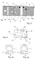
- Fig. 1a
- die Draufsicht einer ersten möglichen Konstruktion der erfindungsgemäßen integrierten Baueinheit bestehend aus Batteriesensor und Befestigungsvorrichtung in zweidimensionaler Darstellung,
- Fig. 1b
- den Schnitt B-B durch Fig. 1a,
- Fig. 2
- die erste mögliche Konstruktion der erfindungsgemäßen integrierten Baueinheit bestehend aus Batteriesensor und Befestigungsvorrichtung in dreidimensionaler Darstellung,
- Fig. 3
- eine genauere schematische Darstellung des Batteriesensors bestehend aus dem Meßshunt und der Elektronikeinheit,
- Fig. 4
- eine genauere schematische Darstellung der Elektronikeinheit,
- Fig. 5a
- schematisch eine zweite mögliche Konstruktion der erfindungsgemäßen integrierten Baueinheit bestehend aus Batteriesensor und Befestigungsvorrichtung in zweidimensionaler Darstellung,
- Fig. 5b
- eine leicht von Fig. 5a abgewandelte Konstruktion,
- Fig. 6a
- und
- Fig. 6b
- weitere Möglichkeiten zur Befestigung der Elektronikeinheit auf dem Meßshunt,
- Fig. 7a
- eine erste Ausgestaltung des Meßshunts und
- Fig. 7b
- eine zweite Ausgestaltung des Meßshunts.
- Fig. 1a
- the top view of a first possible construction of the integrated assembly according to the invention consisting of a battery sensor and fastening device in a two-dimensional representation,
- Fig. 1b
- the section BB through Fig. 1a,
- Fig. 2
- the first possible construction of the integrated assembly according to the invention consisting of a battery sensor and fastening device in a three-dimensional representation,
- Fig. 3
- a more precise schematic representation of the battery sensor consisting of the measuring shunt and the electronics unit,
- Fig. 4
- a more precise schematic representation of the electronics unit,
- Fig. 5a
- schematically a second possible construction of the integrated assembly according to the invention consisting of a battery sensor and fastening device in a two-dimensional representation,
- Fig. 5b
- a construction slightly modified from FIG. 5a,
- Fig. 6a
- and
- Fig. 6b
- further options for attaching the electronic unit to the measuring shunt,
- Fig. 7a
- a first embodiment of the measuring shunt and
- Fig. 7b
- a second embodiment of the measuring shunt.
In Fig. 1a ist die Befestigungsvorrichtung des Batteriesensors als vorzugsweise
übliche Batterie-Messingklemme bestehend aus einem Klemmenkörper
1 und einer Klemmschraube 2 dargestellt. Der Batteriesensor 3, 4 ist im
wesentlichen aus einem Meßshunt 3 und einer Elektronikeinheit 4 aufgebaut.
In Fig. 1a sind lediglich die zwei als mechanische Träger ausgebildeten
Widerstandsanschlüsse (10a, 10b; vgl. auch Fig. 2) des Meßshunts 3 und
eine Kunststoffumspritzung der Elektronikeinheit 4 zu sehen. Der Batteriesensor
3,4 und die Befestigungsvorrichtung 1, 2 sind erfindungsgemäß zu
einer integrierten Baueinheit zusammengefaßt. Die Befestigungsvorrichtung
1,2 muß nur an einem einzigen Pol einer Batterie, z. B. am Minuspol, angeschlossen
werden. Die Baueinheit, bestehend aus der Befestigungsvorrichtung
1, 2 und dem Batteriesensor 3,4, ist in Form und Größe an die (hier
nicht eigens dargestellte) bekannte, nach der polnischen DIN 72311 (Teil15)
spezifizierte Batteriepolwanne angepaßt.In Fig. 1a, the fastening device of the battery sensor is preferred
Common battery brass clamp consisting of a
Der erste, in Fig. 1a oben dargestellte Widerstandsanschluß 10a ist leitend,
der zweite, in Fig. 1a unten dargestellte Widerstandsanschluß 10b ist isolierend
über ein Isolierteil 6 am Klemmenkörper 1 befestigt. Am zweiten Widerstandsanschluß
10b ist beispielsweise mittels einer Schraube 5 und einer
im Isolierteil 6 eingebetteten Schraubenmutter 7 (vgl. Fig. 1b) der Kabelschuh
eines gewöhnlichen Anschlußkabels anschließbar. Beim vorliegenden
Ausführungsbeispiel, bei dem die Klemme 1, 2 am Minuspol der Batterie angeschlossen
werden soll, verbindet das (hier nicht dargestellte) Anschlußkabel
den ausgangsseitigen Widerstandsanschluß 10b des Meßshunts 3 mit
der Kraftfahrzeugmasse.The
In Fig. 2 ist zur Verdeutlichung der Erfindung die in Fig. 1a und 1b dargestellte Baueinheit dreidimensional dargestellt. Die gleichen Bauteile sind mit gleichen Bezugszeichen versehen.In Fig. 2 is to illustrate the invention that shown in Fig. 1a and 1b Unit represented three-dimensionally. The same components are the same Provide reference numerals.
In Fig. 3 sind im wesentlichen die Details des Meßshunts 3, mögliche Anordnungen
eines Temperatursensors 13, 13a oder 13b und einer möglichen
Verbindung dieser Bauteile mit der Elektronikeinheit 4 dargestellt. Der
Meßshunt 3 besteht aus einem Widerstandselement 11 und zwei planaren
Widerstandsanschlüssen 10a und 10b. Die Widerstandsanschlüsse 10a und
10b sind vorzugsweise stabil ausgebildete Kupferflächen. Das Material des
Widerstandselements 1 ist vorzugsweise Manganin, Zeranin oder Isaohm.
Kupfer und Manganin/Zeranin/lsaohm weisen in etwa den gleichen Temperaturausdehnungskoeffizienten
wie das übliche Platinenmaterial FR4
(Mischmaterial mit Epoxyharz als Hauptbestandteil) auf. Dieses Platinenmaterial
wird vorzugsweise auch für die Trägerplatine 12 der Elektronikeinheit 4
verwendet, die in Fig. 3 ohne Kunststoffumspritzung dargestellt ist. Daher
kann die Trägerplatine 12 der Elektronikeinheit 4 gemäß Fig. 3 ähnlich der
SMD-Technik über bloße Lötstellen 14 an den Widerstandsanschlüssen 10a
und 10b befestigt werden. Alternativ kann die Trägerplatine 12 auch über um
90° nach oben gebogene kurze Senseleitungen der Widerstandsanschlüsse
10a und 10b am Meßshunt 3 leitend befestigt werden. Die Lötstellen 14 oder
die Anschlüsse der Senseleitungen sind möglichst nahe am Widerstandselement
11 angeordnet. Über die Lötstellen 14 wird das Widerstandselement
11 schaltungstechnisch in die Elektronikeinheit 4 integriert.In Fig. 3 are the details of the measuring
Die Elektronikeinheit 4 bzw. die Trägerplatine 12 ist in Fig. 3 mit einem Temperatursensor
13 zur Messung der Batterietemperatur verbunden. Alternative
Anordnungen des Temperatursensors sind gestrichelt mit den Bezugszeichen
13a und 13 b dargestellt. Der Temperatursensor 13 ist wärmeleitend
beispielsweise mittels Wärmeleitkleber direkt am Klemmenkörper 1 angeordnet.
Diese Anordnung ermöglicht eine sehr genaue Temperaturmessung,
ist jedoch etwas aufwendiger als die Anordnung der Temperatursensoren
13a und 13b, die wärmeleitend am Widerstandsanschluß 10b angebracht
sind. Der Temperatursensor 13a ist vereinfacht über Anschlußdrähte mit der
Trägerplatine 12 befestigt. Der Temperatursensor 13b ist beispielsweise über
Lötstellen mit der Trägerplatine 12 verbunden, um die Anschlußdrähte zu
verhindern. Für den Temperatursensor 13b ist jedoch ggf. eine Aussparung
in der Trägerplatine 12 erforderlich.The
Die Elektronikeinheit 4 bzw. die Trägerplatine 12 weist einen beispielsweise
zweipoligen Stecker 16 auf. Am Pin 18 des Steckers 16 ist ein Versorgungskabel
zum anderen Pol der Batterie, hier zum Pluspol, anschließbar. Am Pin
17 des Steckers 16 ist beispielsweise eine bidirektionale Kommunikationsleitung
zu anderen Elektronikgeräten im Kraftfahrzeug anschließbar. Alternativ
kann die Kommunikationsleitung auch zwei Pins benötigen (z. B. bei Verwendung
eines CAN-Buses). In einer dritten Alternative kann die Kommunikation
jedoch auch per Funkübertragung vorgenommen werden. Anstelle
einer Verbindung über einen Stecker 16 kann aus Platzspargründen auch
eine direkte Verbindung der Anschlussleitungen mit der Platine vorgesehen
werden (z. B. durch Löten, Bonden oder Schweißen). (Die Alternativen sind
hier nicht dargestellt.)The
Schließlich ist in Fig. 3 und in Fig. 4 ein erster Spannungsabgriff 15 zur Messung
der Batteriespannung UBatt gezeigt, der mit dem batteriepolseitigen (z.
B. zum Minuspol) Widerstandsanschluß 10a leitend verbunden ist. Der zweite
Spannungsabgriff zur Messung der Batteriespannung UBatt wird durch den
Pin 18 gebildet (z. B. zum Pluspol der Batterie).Finally, a
In Fig. 4 sind weitere Details der Trägerplatine 12 bzw. der Elektronikeinheit
4 dargestellt. Die Trägerplatine 12 bzw. die Elektronikeinheit 4 weist eine
Meß-, Auswerte- und Steuereinheit 20 auf. Die Einheit 20 erfaßt die Batteriespannung
UBatt, die Spannung U zwischen den beiden Lötstellen 14 und die
Batterietemperatur. Aus der Spannung U kann der Batteriestrom (I) berechnet
werden. Hierzu ist beispielsweise der Widerstandswert (R) des Widerstandselements
11 in der Einheit 20 abgespeichert. Die Einheit 20 weist vorzugsweise
einen Mikroprozessor und einen Speicher auf. Auch kann die
Einheit 20 übliche Verstärker und A/D-Wandler zur Meßaufbereitung enthalten.
Die Einheit 20 kann beliebige weitere Batterie-Indikatorgrößen, wie z. B.
den Ladezustand oder den Alterungszustand, ermittelt. Weiterhin kann die
Einheit 20 ihrerseits über die Kommunikationsleitung nicht nur Informationen
übertragen, sondern auch weitere Informationen von anderen Steuergeräten
erhalten und diese mit den Batteriegrößen weiterverarbeiten. Die Kommunikationsleitung
und die Versorgungsleitung zum Stecker 16 sind als Kabelbaum
21 zusammengefaßt dargestellt.4 shows further details of the
Abhängig von den der Einheit 20 vorliegenden Informationen kann diese einen
Leistungsschalter 19 ansteuern, der eine im Widerstandsanschluß 10b
vorliegende Unterbrechung schließen oder öffnen kann. Hierbei kann beispielsweise
in Notfällen die Batterieversorgung des Kraftfahrzeuges abgeschaltet
werden. Alternativ kann hierzu der Leistungsschalter 19 auch in einen
der beiden Anschlusskabel zum Pluspol oder zum Minuspol der Batterie
integriert und von der Einheit 20 angesteuert werden.Depending on the information available to the
In Fig. 5a ist ergänzend lediglich schematisch eine zweite mögliche Konstruktion
der erfindungsgemäßen integrierten Baueinheit bestehend aus Batteriesensor
und Befestigungsvorrichtung dargestellt. Hierbei wird durch die
strichpunktierte Linie die Bohrung für die Klemmschraube 2 angedeutet. Diese
Konstruktion weicht nur darin von der ersten Konstruktion ab, daß der
Batteriesensor 3, 4 örtlich stärker von der Klemmschraube 2 abgesetzt ist
und damit von möglichen Verspannungen bei einer Befestigung des Klemmkörpers
1 entkoppelt ist.In Fig. 5a is a schematic of a second possible construction
the integrated assembly according to the invention consisting of a battery sensor
and fastening device shown. Here is by the
dash-dotted line indicated the hole for the clamping
Fig. 5b zeigt eine der Fig. 5a sehr ähnliche Konstruktion, bei der jedoch zwischen
dem Klemmkörper 1 und dem Meßshunt 3 eine Verjüngung vorgesehen
ist, um Materialspannungen im Klemmkörper 1 zu vermeiden.Fig. 5b shows a construction very similar to Fig. 5a, but in which between
the clamping
In den Figuren 6a bis 7b sind weitere Ausgestaltungsmöglichkeiten des
Meßshunts 3 bestehend aus dem Widerstandselement 11 und den beiden
Widerstandsanschlüssen 10a und 10b sowie der Befestigung der Elektronikeinheit
4 bzw. deren Trägerplatine 12 dargestellt. Die Widerstandsanschlüsse
10a und 10b sind vorzugsweise (wie auch in Fig. 3) planar ausgebildete
Kupferflächen. Das Material des Widerstandselements 1, vorzugsweise
Manganin oder Zeranin, ist wie auch in Fig. 3 zwischen den Widerstandselementen
10a und 10b angeordnet.FIGS. 6a to 7b show further design options for the
Measuring shunts 3 consisting of the
In den Figuren 6a bis 7b ist die Trägerplatine 12 der Elektronikeinheit 4
(auch ähnlich der SMD-Technik) über Lötstellen 14 an den Widerstandsanschlüssen
10a und 10b befestigt. Dabei bilden in Fig. 6a (und in Fig. 7a, Seitenansicht
von Fig. 6a) die Lötstellen 14 eine langgezogene Linie entlang der
Kante der Trägerplatine 12. Hierzu sind vorzugsweise an den Kanten der
Trägerplatine zumindest zum Teil offene Leiterbahnen für die Lötstellen vorgesehen.
Die Lötlinien 14 können auch unterbrochen sein bzw. sich auch
aus beabstandeten Punkten zusammensetzen. Die Ausgestaltung nach Fig.
6a (bzw. Fig. 7a) setzt voraus, dass die Breite der Trägerplatine 12 nicht viel
größer als die Breite des Widerstandelements 11 ist; denn die Verlötung
muss möglichst nahe am Widerstandselement 11 vorgesehen werden. Vorzugsweise
ist die Konstruktion des Meßshunts dabei gemäß Fig. 7a derart,
dass sich zwischen dem Widerstandselement 11 und der Trägerplatine 12
ein Hohlraum ergibt. Die Dicke des Widerstandselementes 11 ist also kleiner
als die der Widerstandsanschlüsse 10a und 10b. Durch diesen Hohlraum ist
es möglich, die Trägerplatine 12 bei Bedarf beidseitig zu bestücken.In FIGS. 6a to 7b, the
Alternativ kann gemäß Fig. 6b (und Fig. 7b, Seitenansicht von Fig. 6b) die
Trägerplatine 12 auch durch Lötstellen 14 an der Unterseite der Platine 12
mit den Widerstandsanschlüssen 10a und 10b möglichst nahe am Widerstandselement
11 verbunden sein (ähnlich Fig. 3). Im Unterschied zu Fig. 3
wird hierbei zur mechanischen Stabilisierung (wie in Fig. 6a) eine durchgezogen
(Fig. 6b links) oder eine unterbrochene (Fig. 6b rechts) Lötlinie vorgesehen.
Über die Lötstellen 14 wird das Widerstandselement 11 immer auch
schaltungstechnisch in die Elektronikeinheit 4 integriert. Die Ausgestaltung
nach Fig. 6b kann mit der Konstruktion des Meßshunts gemäß Fig. 7a oder
Fig. 7b kombiniert werden. Ist eine Bestückung der Unterseite der Trägerplatine
12 nicht erforderlich, ist eine Konstruktion gemäß Fig. 7b möglich, bei
der kein Hohlraum zwischen dem Widerstandselement 11 und der Trägerplatine
12 vorgesehen ist. Bei einer Ausgestaltung nach Fig. 6b und Fig. 7b
kann die Breite der Trägerplatine 12 auch größer als die Breite des Widerstandelements
11 sein.Alternatively, according to FIG. 6b (and FIG. 7b, side view of FIG. 6b)
Bei jeder Ausgestaltung können anstelle von Lötstellen (14) auch Klebstellen (14), z.B. mittels eines elektrisch leitenden und wärmeleitenden Klebers, vorgesehen werden.In any configuration, instead of solder joints (14), adhesive joints can also be used (14), e.g. by means of an electrically conductive and thermally conductive adhesive, be provided.
Grundsätzlich wird demnach erfindungsgemäß die Elektronikeinheit 4 bzw.
die Trägerplatine 12 der Elektronikeinheit 4 an den planaren Widerstandsanschlüssen
10a und 10b mittels eines elektrisch leitenden Materials 14 (z. B.
Lot oder Kleber) befestigt. Die Löt- oder Klebestellen 14 dienen somit sowohl
zur elektrischen bzw. schaltungstechnischen Integration des Meßshunts bzw.
des Widerstandselements 11 in die Elektronikeinheit 4 als auch zur mechanischen
Befestigung der Elektronikeinheit 4 bzw. deren Trägerplatine 12 am
Meßshunt bzw. an dessen Widerstandsanschlüssen 10a und 10b.In principle, the
Claims (9)
Applications Claiming Priority (3)
| Application Number | Priority Date | Filing Date | Title |
|---|---|---|---|
| DE19961311A DE19961311A1 (en) | 1999-12-18 | 1999-12-18 | Battery sensor device, has attachment device, sensor combined into integrated unit; attachment device is connected to single pole and has conventional terminal |
| DE19961311 | 1999-12-18 | ||
| EP00987376A EP1238288B1 (en) | 1999-12-18 | 2000-12-09 | Battery sensor device |
Related Parent Applications (1)
| Application Number | Title | Priority Date | Filing Date |
|---|---|---|---|
| EP00987376A Division EP1238288B1 (en) | 1999-12-18 | 2000-12-09 | Battery sensor device |
Publications (2)
| Publication Number | Publication Date |
|---|---|
| EP1435524A1 true EP1435524A1 (en) | 2004-07-07 |
| EP1435524B1 EP1435524B1 (en) | 2006-06-21 |
Family
ID=7933323
Family Applications (2)
| Application Number | Title | Priority Date | Filing Date |
|---|---|---|---|
| EP04005840A Expired - Lifetime EP1435524B1 (en) | 1999-12-18 | 2000-12-09 | Battery sensor device |
| EP00987376A Expired - Lifetime EP1238288B1 (en) | 1999-12-18 | 2000-12-09 | Battery sensor device |
Family Applications After (1)
| Application Number | Title | Priority Date | Filing Date |
|---|---|---|---|
| EP00987376A Expired - Lifetime EP1238288B1 (en) | 1999-12-18 | 2000-12-09 | Battery sensor device |
Country Status (8)
| Country | Link |
|---|---|
| US (1) | US6787935B2 (en) |
| EP (2) | EP1435524B1 (en) |
| JP (1) | JP4996802B2 (en) |
| AT (2) | ATE271694T1 (en) |
| DE (3) | DE19961311A1 (en) |
| ES (2) | ES2222263T3 (en) |
| HK (1) | HK1052554B (en) |
| WO (1) | WO2001044825A1 (en) |
Cited By (15)
| Publication number | Priority date | Publication date | Assignee | Title |
|---|---|---|---|---|
| EP1621892A1 (en) * | 2004-07-30 | 2006-02-01 | Hella KGaA Hueck & Co. | Apparatus to Measure an Electrical Current |
| WO2007020129A1 (en) * | 2005-08-19 | 2007-02-22 | Robert Bosch Gmbh | Battery sensor unit |
| WO2008000537A1 (en) * | 2006-06-26 | 2008-01-03 | Robert Bosch Gmbh | Battery sensor unit and method for producing the battery sensor unit |
| WO2009010103A1 (en) * | 2007-07-13 | 2009-01-22 | Auto-Kabel Managementgesellschaft Mbh | Vehicle battery sensor element and method for producing a motor vehicle battery sensor element |
| EP2073030A1 (en) * | 2007-12-19 | 2009-06-24 | Robert Bosch GmbH | Sensor arrangement and diagnosis procedure for detecting the status of a battery in a motor vehicle |
| EP2073028A1 (en) * | 2007-12-19 | 2009-06-24 | Robert Bosch Gmbh | Sensor arrangement for detecting the status of a battery |
| DE102008003338A1 (en) | 2008-01-07 | 2009-07-09 | Robert Bosch Gmbh | Electric current determining device for use in cable i.e. earth cable, has cable provided with cable insulation, where cable insulation is formed such that cable insulation partially encloses measuring element and/or electronic system |
| DE102008003458A1 (en) | 2008-01-08 | 2009-07-09 | Robert Bosch Gmbh | Electric current determining device for energy storage i.e. battery, of motor vehicle, has sensor resistor electrical conductively connected with cable through contact surface that is oriented parallel to cable longitudinal direction |
| DE102008029476A1 (en) | 2008-06-20 | 2010-02-18 | Robert Bosch Gmbh | Non-contact current measuring arrangement for measuring a battery current |
| CZ301558B6 (en) * | 1998-08-05 | 2010-04-14 | Boehringer Ingelheim Pharma Gmbh & Co. Kg. | Capsule for pharmaceutical compositions for powder inhalers |
| EP1677327B1 (en) * | 2004-12-30 | 2010-07-07 | Robert Bosch Gmbh | Energy supply system for vehicle starter |
| DE102016210661A1 (en) * | 2016-06-15 | 2017-12-21 | Continental Automotive Gmbh | Energy-saving storage concept for electronic modules in a motor vehicle |
| EP1374364B1 (en) * | 2001-04-06 | 2018-07-11 | Microchip Technology Incorporated | Terminal assembly for battery |
| WO2018206377A1 (en) * | 2017-05-08 | 2018-11-15 | Robert Bosch Gmbh | Shunt resistor for detecting the status of an electrical energy storage unit |
| WO2021197921A1 (en) * | 2020-03-30 | 2021-10-07 | Sma Solar Technology Ag | Device for temperature measurement and device for current determination |
Families Citing this family (77)
| Publication number | Priority date | Publication date | Assignee | Title |
|---|---|---|---|---|
| DE10118051B4 (en) * | 2001-04-11 | 2005-09-29 | Daimlerchrysler Ag | Battery measuring terminal with jump start point |
| DE10118027B4 (en) * | 2001-04-11 | 2005-11-10 | Daimlerchrysler Ag | Battery terminal with jump start point and integrated measuring sensor |
| DE10332410B3 (en) * | 2003-07-16 | 2004-05-27 | Auto Kabel Managementgesellschaft Mbh | Automobile onboard electrical network sensor device using shunt measuring resistance integrated in onboard electrical network |
| DE10336107B3 (en) * | 2003-08-06 | 2005-04-28 | Siemens Ag | Measuring resistance for battery sensor unit in automobile provided by plate-shaped rectangular base element with measuring track connected to contact terminals along one side and relatively spaced parallel slit |
| DE10347111B4 (en) * | 2003-10-10 | 2013-02-21 | Continental Automotive Gmbh | Integrated battery terminal |
| DE102004006298B4 (en) | 2004-02-09 | 2006-08-17 | Siemens Ag | Connecting arrangement for a measuring element of a battery sensor |
| DE102004007851B4 (en) * | 2004-02-17 | 2006-03-16 | Kromberg & Schubert Gmbh & Co. Kg | Connection device for a battery |
| DE102004013659A1 (en) * | 2004-03-19 | 2005-10-13 | Siemens Ag | Device for detecting an electrical quantity of a rechargeable battery |
| DE102004033127B3 (en) * | 2004-07-08 | 2006-04-20 | Siemens Ag | Test circuit for determining electrical parameter of accumulator battery has clamp engaging battery terminal and precision resistor between connectors connected to evaluation circuits |
| JP4494895B2 (en) * | 2004-07-20 | 2010-06-30 | 古河電気工業株式会社 | Battery status detection unit |
| DE102004037874B4 (en) * | 2004-08-04 | 2008-09-04 | Continental Automotive Gmbh | Battery sensor arrangement |
| DE102004040575A1 (en) * | 2004-08-21 | 2006-02-23 | Abb Patent Gmbh | Device for measuring electrical current, voltage and temperature on an electrical conductor made of rigid material |
| DE102004046855B3 (en) * | 2004-09-27 | 2006-04-13 | Siemens Ag | Batteriepolklemmenanordnung |
| DE102004049251A1 (en) * | 2004-09-30 | 2006-04-06 | Robert Bosch Gmbh | Device for determining electrical quantities |
| DE102004049153A1 (en) * | 2004-09-30 | 2006-04-06 | Robert Bosch Gmbh | Main conductor for a device like a battery sensor for detecting electric capacities routes a load current between a source of electric energy and electric consumers |
| DE102004053648A1 (en) * | 2004-11-03 | 2006-05-04 | Leopold Kostal Gmbh & Co. Kg | Battery current sensor for a motor vehicle |
| DE102004055848B4 (en) * | 2004-11-19 | 2008-02-21 | Bayerische Motoren Werke Ag | Battery sensor device |
| DE102004055849A1 (en) * | 2004-11-19 | 2006-06-01 | Bayerische Motoren Werke Ag | Motor vehicle battery sensor device, has electronic unit attached with connection points such that ohmic resistor formed between connection points is technically integrated in electronic unit |
| DE102004055847B4 (en) * | 2004-11-19 | 2007-01-11 | Bayerische Motoren Werke Ag | Method for manufacturing a battery sensor device |
| FR2879751B1 (en) * | 2004-12-20 | 2007-02-23 | Johnson Controls Tech Co | DEVICE FOR MEASURING CIRCULATING CURRENT IN A CABLE |
| DE102005041392B4 (en) * | 2005-04-07 | 2016-02-18 | Kromberg & Schubert Kg | connecting device |
| DE102005019569A1 (en) * | 2005-04-27 | 2006-11-09 | Siemens Ag | Shunt for use in battery sensor, has two electrically connecting units as, respectively, pole clamp and cable socket, where pole clamp contains brass and is material-conclusively connected with resistance unit by braze welding |
| DE102005021959A1 (en) * | 2005-05-12 | 2006-11-23 | Leopold Kostal Gmbh & Co. Kg | Battery current sensor for a motor vehicle |
| DE102005034427A1 (en) * | 2005-07-13 | 2007-01-18 | Robert Bosch Gmbh | Annular terminal clamp for vehicle starter battery, has integral formation accepting impacts for mounting, whilst protecting other components from blows |
| US7385828B2 (en) * | 2006-01-27 | 2008-06-10 | Delphi Technologies, Inc. | Electronic shunt resistor assembly |
| DE102007006050B8 (en) * | 2006-02-04 | 2013-04-04 | Kromberg & Schubert Kg | connecting device |
| DE102006036247A1 (en) * | 2006-02-16 | 2007-08-23 | Kromberg & Schubert Gmbh & Co. Kg | Terminal device e.g. for current measurement of motor vehicle battery, has pin-shaped section for positioning in battery terminal recess |
| US7688022B2 (en) | 2006-02-17 | 2010-03-30 | Lear Corporation | Energy management system for a vehicle |
| DE102006019497B4 (en) * | 2006-04-26 | 2009-04-23 | Continental Automotive Gmbh | Sensor device for a starter battery in a motor vehicle |
| DE112006003786A5 (en) * | 2006-04-28 | 2009-03-05 | Daimler Ag | A fuel cell device with a current sensor and current sensor for a fuel cell device |
| DE102006038373A1 (en) * | 2006-08-12 | 2008-02-14 | Robert Bosch Gmbh | Electrical device, especially for determining electrical parameters, e.g. battery sensor, has conductive boundary surface between two conductor sections that is offset relative to the central axis |
| US7381101B2 (en) * | 2006-08-25 | 2008-06-03 | Lear Corporation | Battery post connector |
| DE102006046137B4 (en) * | 2006-09-28 | 2019-02-14 | Continental Automotive Gmbh | Battery sensor unit |
| DE102006050573B4 (en) * | 2006-10-26 | 2017-03-09 | Audi Ag | Electrical safety device for battery-connected electrical consumers of a vehicle |
| DE102006058135A1 (en) * | 2006-12-09 | 2008-06-26 | Kromberg & Schubert Gmbh & Co. Kg | Battery terminal clamp for connecting battery to on-board electrical system of vehicle, comprises two components, where former component is connected to pole of battery and latter component is connected to on-board electrical system |
| US7500888B2 (en) * | 2007-02-08 | 2009-03-10 | Lear Corporation | Battery post connector |
| DE102007009569B4 (en) | 2007-02-27 | 2011-06-16 | Kromberg & Schubert Gmbh & Co. Kg | Connection device and method for its production |
| DE102007021921B4 (en) * | 2007-05-10 | 2009-03-19 | Siemens Ag | Device for monitoring an energy store |
| US8476864B2 (en) | 2007-06-13 | 2013-07-02 | Lear Corporation | Battery monitoring system |
| JP4442660B2 (en) | 2007-08-10 | 2010-03-31 | 株式会社デンソー | Vehicle system |
| US20090160456A1 (en) * | 2007-12-19 | 2009-06-25 | Kuen-Cheng Wang | Device for inspecting soldering spots in a storage battery |
| US8174275B2 (en) * | 2007-12-19 | 2012-05-08 | Kuen-Cheng Wang | Storage battery inspecting system |
| JP2009177903A (en) * | 2008-01-23 | 2009-08-06 | Denso Corp | Vehicle system |
| DE102008006183A1 (en) * | 2008-01-26 | 2009-07-30 | Hella Kgaa Hueck & Co. | Device for current measurement |
| KR100910883B1 (en) | 2008-01-30 | 2009-08-06 | 동아전장주식회사 | Manufacturing method of Battery Sensor for Vehicle |
| DE102008006866A1 (en) * | 2008-01-31 | 2009-08-06 | Hella Kgaa Hueck & Co. | Device for current measurement |
| DE102008013407A1 (en) * | 2008-03-10 | 2009-09-17 | Robert Bosch Gmbh | Sensor arrangement for e.g. condition detection of battery of motor vehicle, has housing corresponding to design of standardized securing elements that are plug-in fuses provided with two flat parallel connecting contacts |
| GB0805585D0 (en) * | 2008-03-27 | 2008-04-30 | Ultra Electronics Ltd | Current measurement apparatus |
| DE202008017964U1 (en) | 2008-06-23 | 2011-01-05 | Iq Power Licensing Ag | Battery cover construction with battery pole |
| DE102008040243A1 (en) | 2008-07-08 | 2010-01-14 | Robert Bosch Gmbh | Pole terminal arrangement for connection of load circuit at motor vehicle battery for detecting load current of battery, has resistor attached at terminal in conducting manner, and resistor connector guided to connector for load circuit |
| US8305034B2 (en) * | 2008-07-23 | 2012-11-06 | Lear Corporation | Battery monitoring system |
| DE102009000827A1 (en) * | 2009-02-13 | 2010-08-19 | Robert Bosch Gmbh | Device and method for connecting at least two electrical connections |
| DE102009001374A1 (en) | 2009-03-06 | 2010-09-09 | Robert Bosch Gmbh | Safety system i.e. theft safety system, for battery sensors in load circuit of vehicle for detecting battery condition, has electronic components connected with assemblies, where identification feature is adjusted during installation change |
| ES2381704B1 (en) | 2009-09-23 | 2013-05-08 | Cablerias Auto, S.L | SMART BATTERY CABLE |
| DE102009044992A1 (en) | 2009-09-24 | 2011-04-14 | Robert Bosch Gmbh | Method for improvement of current measurement accuracy of battery sensor, involves evaluating physical measurements for measuring voltage drop in region of shunts in load circuit of battery |
| DE102009045310A1 (en) * | 2009-10-02 | 2011-04-07 | Robert Bosch Gmbh | Current measuring arrangement for use in current circuit of battery of motor vehicle, has shunts fixed between supply elements such that heat capacity of shunts and/or adjacent areas of elements serve as cooling body for power components |
| JP5723139B2 (en) * | 2010-04-30 | 2015-05-27 | 矢崎総業株式会社 | Battery terminal unit with current sensor |
| DE102010036397A1 (en) | 2010-07-14 | 2012-01-19 | Dr. Ing. H.C. F. Porsche Aktiengesellschaft | Battery sensor device for detecting and monitoring e.g. motor vehicle starter battery, has communication interface automatically detecting cytochemistry of battery, so that battery sensor is automatically adapted to detected cytochemistry |
| EP2434583A1 (en) * | 2010-09-28 | 2012-03-28 | Liaisons Electroniques-Mecaniques Lem S.A. | Battery current sensor |
| JP5873626B2 (en) * | 2010-10-06 | 2016-03-01 | 矢崎総業株式会社 | Current detector that can accurately measure busbar temperature |
| US20130073235A1 (en) * | 2011-03-17 | 2013-03-21 | Isophi Bvba | Battery monitoring devices |
| DE102011111081B4 (en) * | 2011-08-18 | 2021-08-05 | Isabellenhütte Heusler Gmbh & Co. Kg | Battery sensor |
| DE102012210262A1 (en) | 2011-11-18 | 2013-05-23 | Robert Bosch Gmbh | Battery with a battery cell with external and integrated temperature sensor and method of operation of the battery |
| JP6094856B2 (en) * | 2012-09-28 | 2017-03-15 | 株式会社Gsユアサ | Power storage device, vehicle, and connection terminal |
| EP2738562B1 (en) * | 2012-11-30 | 2015-01-07 | Isabellenhütte Heusler GmbH & Co.KG | Battery sensor |
| US20140152313A1 (en) * | 2012-12-03 | 2014-06-05 | Isabellenhuette Heusler Gmbh & Co. Kg | Battery sensor |
| DE102013010166A1 (en) * | 2013-06-19 | 2015-01-08 | Auto-Kabel Management Gmbh | Polish integrated starting current limiter |
| US9226412B2 (en) * | 2013-08-02 | 2015-12-29 | Lear Corporation | Housing with air chamber for battery monitor system and method for manufacturing same |
| USD777055S1 (en) | 2014-04-19 | 2017-01-24 | Mark Taylor | Battery monitoring clamp |
| USD777669S1 (en) | 2014-04-19 | 2017-01-31 | Mark Taylor | Battery monitoring clip |
| CN106575802A (en) * | 2014-09-16 | 2017-04-19 | 松下知识产权经营株式会社 | Battery sensor device |
| US20160146900A1 (en) * | 2014-11-24 | 2016-05-26 | Hyundai Mobis Co., Ltd. | Battery sensor assembly for vehicle |
| JP2019169396A (en) * | 2018-03-23 | 2019-10-03 | ダイハツ工業株式会社 | Battery temperature estimation device |
| USD853309S1 (en) * | 2018-03-27 | 2019-07-09 | Mt. Ida Machining, Inc. | Automobile battery pole connector set |
| DE102018209325A1 (en) | 2018-06-12 | 2019-12-12 | Bayerische Motoren Werke Aktiengesellschaft | Measurements on batteries |
| DE102019121980A1 (en) * | 2019-01-22 | 2020-07-23 | Roman Nachsel | High current component |
| WO2023112985A1 (en) * | 2021-12-16 | 2023-06-22 | 古河電気工業株式会社 | Battery status detection device, information processing system, and data collection method |
Citations (4)
| Publication number | Priority date | Publication date | Assignee | Title |
|---|---|---|---|---|
| US4572878A (en) * | 1984-12-19 | 1986-02-25 | General Motors Corporation | Battery temperature sensor and housing therefor |
| DE3532044A1 (en) * | 1985-09-09 | 1987-03-19 | Vdo Schindling | POLE CLAMP |
| US5877563A (en) * | 1995-02-06 | 1999-03-02 | Bayerische Motoren Werke Aktiengellschaft | Fuse device for a cable in motor vehicles |
| WO1999054744A1 (en) * | 1998-04-17 | 1999-10-28 | Menico Ag | Battery measuring terminal |
Family Cites Families (1)
| Publication number | Priority date | Publication date | Assignee | Title |
|---|---|---|---|---|
| DE2535245A1 (en) * | 1975-08-07 | 1977-02-24 | Bosch Gmbh Robert | BATTERY CHARGER |
-
1999
- 1999-12-18 DE DE19961311A patent/DE19961311A1/en not_active Withdrawn
-
2000
- 2000-12-09 EP EP04005840A patent/EP1435524B1/en not_active Expired - Lifetime
- 2000-12-09 US US10/168,023 patent/US6787935B2/en not_active Expired - Lifetime
- 2000-12-09 EP EP00987376A patent/EP1238288B1/en not_active Expired - Lifetime
- 2000-12-09 JP JP2001545861A patent/JP4996802B2/en not_active Expired - Lifetime
- 2000-12-09 AT AT00987376T patent/ATE271694T1/en active
- 2000-12-09 WO PCT/EP2000/012457 patent/WO2001044825A1/en active IP Right Grant
- 2000-12-09 AT AT04005840T patent/ATE331224T1/en active
- 2000-12-09 DE DE50007155T patent/DE50007155D1/en not_active Expired - Lifetime
- 2000-12-09 ES ES00987376T patent/ES2222263T3/en not_active Expired - Lifetime
- 2000-12-09 DE DE50013075T patent/DE50013075D1/en not_active Expired - Lifetime
- 2000-12-09 ES ES04005840T patent/ES2265124T3/en not_active Expired - Lifetime
-
2003
- 2003-07-09 HK HK03104924.0A patent/HK1052554B/en not_active IP Right Cessation
Patent Citations (4)
| Publication number | Priority date | Publication date | Assignee | Title |
|---|---|---|---|---|
| US4572878A (en) * | 1984-12-19 | 1986-02-25 | General Motors Corporation | Battery temperature sensor and housing therefor |
| DE3532044A1 (en) * | 1985-09-09 | 1987-03-19 | Vdo Schindling | POLE CLAMP |
| US5877563A (en) * | 1995-02-06 | 1999-03-02 | Bayerische Motoren Werke Aktiengellschaft | Fuse device for a cable in motor vehicles |
| WO1999054744A1 (en) * | 1998-04-17 | 1999-10-28 | Menico Ag | Battery measuring terminal |
Cited By (18)
| Publication number | Priority date | Publication date | Assignee | Title |
|---|---|---|---|---|
| CZ301558B6 (en) * | 1998-08-05 | 2010-04-14 | Boehringer Ingelheim Pharma Gmbh & Co. Kg. | Capsule for pharmaceutical compositions for powder inhalers |
| EP1374364B1 (en) * | 2001-04-06 | 2018-07-11 | Microchip Technology Incorporated | Terminal assembly for battery |
| EP2256900B1 (en) * | 2001-04-06 | 2018-10-03 | Microchip Technology Incorporated | Terminal Assembly for a Battery |
| EP1621892A1 (en) * | 2004-07-30 | 2006-02-01 | Hella KGaA Hueck & Co. | Apparatus to Measure an Electrical Current |
| EP1677327B1 (en) * | 2004-12-30 | 2010-07-07 | Robert Bosch Gmbh | Energy supply system for vehicle starter |
| WO2007020129A1 (en) * | 2005-08-19 | 2007-02-22 | Robert Bosch Gmbh | Battery sensor unit |
| WO2008000537A1 (en) * | 2006-06-26 | 2008-01-03 | Robert Bosch Gmbh | Battery sensor unit and method for producing the battery sensor unit |
| US8232805B2 (en) | 2006-06-26 | 2012-07-31 | Robert Bosch Gmbh | Battery sensor unit and method for manufacturing the battery sensor unit |
| WO2009010103A1 (en) * | 2007-07-13 | 2009-01-22 | Auto-Kabel Managementgesellschaft Mbh | Vehicle battery sensor element and method for producing a motor vehicle battery sensor element |
| EP2073028A1 (en) * | 2007-12-19 | 2009-06-24 | Robert Bosch Gmbh | Sensor arrangement for detecting the status of a battery |
| EP2073030A1 (en) * | 2007-12-19 | 2009-06-24 | Robert Bosch GmbH | Sensor arrangement and diagnosis procedure for detecting the status of a battery in a motor vehicle |
| DE102008003338A1 (en) | 2008-01-07 | 2009-07-09 | Robert Bosch Gmbh | Electric current determining device for use in cable i.e. earth cable, has cable provided with cable insulation, where cable insulation is formed such that cable insulation partially encloses measuring element and/or electronic system |
| DE102008003458A1 (en) | 2008-01-08 | 2009-07-09 | Robert Bosch Gmbh | Electric current determining device for energy storage i.e. battery, of motor vehicle, has sensor resistor electrical conductively connected with cable through contact surface that is oriented parallel to cable longitudinal direction |
| DE102008029476A1 (en) | 2008-06-20 | 2010-02-18 | Robert Bosch Gmbh | Non-contact current measuring arrangement for measuring a battery current |
| DE102016210661A1 (en) * | 2016-06-15 | 2017-12-21 | Continental Automotive Gmbh | Energy-saving storage concept for electronic modules in a motor vehicle |
| WO2018206377A1 (en) * | 2017-05-08 | 2018-11-15 | Robert Bosch Gmbh | Shunt resistor for detecting the status of an electrical energy storage unit |
| US11422157B2 (en) | 2017-05-08 | 2022-08-23 | Robert Bosch Gmbh | Shunt resistor for detecting the status of an electrical energy storage unit |
| WO2021197921A1 (en) * | 2020-03-30 | 2021-10-07 | Sma Solar Technology Ag | Device for temperature measurement and device for current determination |
Also Published As
| Publication number | Publication date |
|---|---|
| EP1238288B1 (en) | 2004-07-21 |
| ES2265124T3 (en) | 2007-02-01 |
| EP1238288A1 (en) | 2002-09-11 |
| DE50013075D1 (en) | 2006-08-03 |
| WO2001044825A1 (en) | 2001-06-21 |
| EP1435524B1 (en) | 2006-06-21 |
| ATE271694T1 (en) | 2004-08-15 |
| WO2001044825A8 (en) | 2014-10-02 |
| JP2003517613A (en) | 2003-05-27 |
| DE50007155D1 (en) | 2004-08-26 |
| ES2222263T3 (en) | 2005-02-01 |
| JP4996802B2 (en) | 2012-08-08 |
| ATE331224T1 (en) | 2006-07-15 |
| HK1052554A1 (en) | 2003-09-19 |
| US20030057770A1 (en) | 2003-03-27 |
| DE19961311A1 (en) | 2001-07-26 |
| US6787935B2 (en) | 2004-09-07 |
| HK1052554B (en) | 2005-10-07 |
Similar Documents
| Publication | Publication Date | Title |
|---|---|---|
| EP1238288B1 (en) | Battery sensor device | |
| EP1253430B1 (en) | Procedure and device for current monitoring in a power distribution network | |
| EP2274749B1 (en) | Electronic component and corresponding production method | |
| DE102004007851B4 (en) | Connection device for a battery | |
| DE69530726T2 (en) | MEASURING DEVICE FOR MAGNETIC FIELDS | |
| DE102011111081B4 (en) | Battery sensor | |
| EP1644749B1 (en) | Sensor unit for an on-board network of a motor vehicle, and method for the production of a sensor unit | |
| DE102008021407A1 (en) | Battery Monitoring System | |
| WO2005005998A1 (en) | Measuring method and measuring arrangement for measuring currents with a large dynamic range | |
| DE102007020882B4 (en) | Device for checking the attachment of a printed circuit board to a carrier | |
| DE102011000943A1 (en) | current sensor | |
| DE102011016373A1 (en) | Battery block for use as energy storage in motor car, has contact elements provided at circuit board in sections, and monitoring and balancing circuits in contact with power connector at battery cells on circuit board via contact elements | |
| EP1001220B1 (en) | Glow pin plug | |
| DE102008029476B4 (en) | Contactless current measuring arrangement for measuring a battery current | |
| DE102012211701A1 (en) | Measuring resistor for current sensor and current sensor unit | |
| EP1213189B1 (en) | Device for monitoring a vehicle power supply network | |
| DE102009034409B4 (en) | Battery monitoring system | |
| DE102008006866A1 (en) | Device for current measurement | |
| EP2737327B1 (en) | Circuit for conducting an electrical current | |
| DE102007006050B4 (en) | connecting device | |
| DE102006054369A1 (en) | Sensor arrangement for use in motor vehicle, has circuit arrangement connected with contact areas of supply bus and designed to detect parameter representing electrical current flowing between connections of sensor arrangement | |
| DE102008040243A1 (en) | Pole terminal arrangement for connection of load circuit at motor vehicle battery for detecting load current of battery, has resistor attached at terminal in conducting manner, and resistor connector guided to connector for load circuit | |
| EP2831601B1 (en) | Electronic battery sensor | |
| DE102019121385A1 (en) | DEVICE AND METHOD FOR MOUNTING A MAGNETIC FIELD SENSOR CHIP ON A TRACK | |
| EP2811313A1 (en) | Battery sensor |
Legal Events
| Date | Code | Title | Description |
|---|---|---|---|
| PUAI | Public reference made under article 153(3) epc to a published international application that has entered the european phase |
Free format text: ORIGINAL CODE: 0009012 |
|
| 17P | Request for examination filed |
Effective date: 20040311 |
|
| AC | Divisional application: reference to earlier application |
Ref document number: 1238288 Country of ref document: EP Kind code of ref document: P |
|
| AK | Designated contracting states |
Kind code of ref document: A1 Designated state(s): AT BE CH CY DE DK ES FI FR GB GR IE IT LI LU MC NL PT SE TR |
|
| 17Q | First examination report despatched |
Effective date: 20041019 |
|
| AKX | Designation fees paid |
Designated state(s): AT BE CH CY DE DK ES FI FR GB GR IE IT LI LU MC NL PT SE TR |
|
| GRAP | Despatch of communication of intention to grant a patent |
Free format text: ORIGINAL CODE: EPIDOSNIGR1 |
|
| GRAS | Grant fee paid |
Free format text: ORIGINAL CODE: EPIDOSNIGR3 |
|
| GRAA | (expected) grant |
Free format text: ORIGINAL CODE: 0009210 |
|
| AC | Divisional application: reference to earlier application |
Ref document number: 1238288 Country of ref document: EP Kind code of ref document: P |
|
| AK | Designated contracting states |
Kind code of ref document: B1 Designated state(s): AT BE CH CY DE DK ES FI FR GB GR IE IT LI LU MC NL PT SE TR |
|
| PG25 | Lapsed in a contracting state [announced via postgrant information from national office to epo] |
Ref country code: NL Free format text: LAPSE BECAUSE OF FAILURE TO SUBMIT A TRANSLATION OF THE DESCRIPTION OR TO PAY THE FEE WITHIN THE PRESCRIBED TIME-LIMIT Effective date: 20060621 Ref country code: FI Free format text: LAPSE BECAUSE OF FAILURE TO SUBMIT A TRANSLATION OF THE DESCRIPTION OR TO PAY THE FEE WITHIN THE PRESCRIBED TIME-LIMIT Effective date: 20060621 Ref country code: IE Free format text: LAPSE BECAUSE OF FAILURE TO SUBMIT A TRANSLATION OF THE DESCRIPTION OR TO PAY THE FEE WITHIN THE PRESCRIBED TIME-LIMIT Effective date: 20060621 |
|
| REG | Reference to a national code |
Ref country code: GB Ref legal event code: FG4D Free format text: NOT ENGLISH |
|
| REG | Reference to a national code |
Ref country code: CH Ref legal event code: EP |
|
| REG | Reference to a national code |
Ref country code: CH Ref legal event code: NV Representative=s name: E. BLUM & CO. PATENTANWAELTE |
|
| REG | Reference to a national code |
Ref country code: IE Ref legal event code: FG4D Free format text: LANGUAGE OF EP DOCUMENT: GERMAN |
|
| GBT | Gb: translation of ep patent filed (gb section 77(6)(a)/1977) |
Effective date: 20060712 |
|
| REF | Corresponds to: |
Ref document number: 50013075 Country of ref document: DE Date of ref document: 20060803 Kind code of ref document: P |
|
| PG25 | Lapsed in a contracting state [announced via postgrant information from national office to epo] |
Ref country code: DK Free format text: LAPSE BECAUSE OF FAILURE TO SUBMIT A TRANSLATION OF THE DESCRIPTION OR TO PAY THE FEE WITHIN THE PRESCRIBED TIME-LIMIT Effective date: 20060921 |
|
| REG | Reference to a national code |
Ref country code: SE Ref legal event code: TRGR |
|
| PG25 | Lapsed in a contracting state [announced via postgrant information from national office to epo] |
Ref country code: PT Free format text: LAPSE BECAUSE OF FAILURE TO SUBMIT A TRANSLATION OF THE DESCRIPTION OR TO PAY THE FEE WITHIN THE PRESCRIBED TIME-LIMIT Effective date: 20061121 |
|
| NLV1 | Nl: lapsed or annulled due to failure to fulfill the requirements of art. 29p and 29m of the patents act | ||
| ET | Fr: translation filed | ||
| PG25 | Lapsed in a contracting state [announced via postgrant information from national office to epo] |
Ref country code: BE Free format text: LAPSE BECAUSE OF NON-PAYMENT OF DUE FEES Effective date: 20061231 Ref country code: MC Free format text: LAPSE BECAUSE OF NON-PAYMENT OF DUE FEES Effective date: 20061231 |
|
| REG | Reference to a national code |
Ref country code: ES Ref legal event code: FG2A Ref document number: 2265124 Country of ref document: ES Kind code of ref document: T3 |
|
| REG | Reference to a national code |
Ref country code: IE Ref legal event code: FD4D |
|
| PLBE | No opposition filed within time limit |
Free format text: ORIGINAL CODE: 0009261 |
|
| STAA | Information on the status of an ep patent application or granted ep patent |
Free format text: STATUS: NO OPPOSITION FILED WITHIN TIME LIMIT |
|
| 26N | No opposition filed |
Effective date: 20070322 |
|
| REG | Reference to a national code |
Ref country code: CH Ref legal event code: PFA Owner name: BAYERISCHE MOTOREN WERKE AKTIENGESELLSCHAFT Free format text: BAYERISCHE MOTOREN WERKE AKTIENGESELLSCHAFT#PETUELRING 130#80809 MUENCHEN (DE) -TRANSFER TO- BAYERISCHE MOTOREN WERKE AKTIENGESELLSCHAFT#PETUELRING 130#80809 MUENCHEN (DE) |
|
| BERE | Be: lapsed |
Owner name: BAYERISCHE MOTOREN WERKE A.G. Effective date: 20061231 |
|
| PG25 | Lapsed in a contracting state [announced via postgrant information from national office to epo] |
Ref country code: GR Free format text: LAPSE BECAUSE OF FAILURE TO SUBMIT A TRANSLATION OF THE DESCRIPTION OR TO PAY THE FEE WITHIN THE PRESCRIBED TIME-LIMIT Effective date: 20060922 |
|
| PG25 | Lapsed in a contracting state [announced via postgrant information from national office to epo] |
Ref country code: LU Free format text: LAPSE BECAUSE OF NON-PAYMENT OF DUE FEES Effective date: 20061209 Ref country code: TR Free format text: LAPSE BECAUSE OF FAILURE TO SUBMIT A TRANSLATION OF THE DESCRIPTION OR TO PAY THE FEE WITHIN THE PRESCRIBED TIME-LIMIT Effective date: 20060621 |
|
| PG25 | Lapsed in a contracting state [announced via postgrant information from national office to epo] |
Ref country code: CY Free format text: LAPSE BECAUSE OF FAILURE TO SUBMIT A TRANSLATION OF THE DESCRIPTION OR TO PAY THE FEE WITHIN THE PRESCRIBED TIME-LIMIT Effective date: 20060621 |
|
| REG | Reference to a national code |
Ref country code: FR Ref legal event code: PLFP Year of fee payment: 16 |
|
| REG | Reference to a national code |
Ref country code: FR Ref legal event code: PLFP Year of fee payment: 17 |
|
| REG | Reference to a national code |
Ref country code: FR Ref legal event code: PLFP Year of fee payment: 18 |
|
| PGFP | Annual fee paid to national office [announced via postgrant information from national office to epo] |
Ref country code: SE Payment date: 20191220 Year of fee payment: 20 Ref country code: DE Payment date: 20191211 Year of fee payment: 20 |
|
| PGFP | Annual fee paid to national office [announced via postgrant information from national office to epo] |
Ref country code: IT Payment date: 20191216 Year of fee payment: 20 Ref country code: FR Payment date: 20191219 Year of fee payment: 20 |
|
| PGFP | Annual fee paid to national office [announced via postgrant information from national office to epo] |
Ref country code: AT Payment date: 20191213 Year of fee payment: 20 Ref country code: CH Payment date: 20191220 Year of fee payment: 20 |
|
| PGFP | Annual fee paid to national office [announced via postgrant information from national office to epo] |
Ref country code: GB Payment date: 20191220 Year of fee payment: 20 Ref country code: ES Payment date: 20200122 Year of fee payment: 20 |
|
| REG | Reference to a national code |
Ref country code: DE Ref legal event code: R071 Ref document number: 50013075 Country of ref document: DE |
|
| REG | Reference to a national code |
Ref country code: CH Ref legal event code: PL |
|
| REG | Reference to a national code |
Ref country code: GB Ref legal event code: PE20 Expiry date: 20201208 |
|
| REG | Reference to a national code |
Ref country code: AT Ref legal event code: MK07 Ref document number: 331224 Country of ref document: AT Kind code of ref document: T Effective date: 20201209 |
|
| PG25 | Lapsed in a contracting state [announced via postgrant information from national office to epo] |
Ref country code: GB Free format text: LAPSE BECAUSE OF EXPIRATION OF PROTECTION Effective date: 20201208 |
|
| REG | Reference to a national code |
Ref country code: SE Ref legal event code: EUG |
|
| REG | Reference to a national code |
Ref country code: ES Ref legal event code: FD2A Effective date: 20220128 |
|
| PG25 | Lapsed in a contracting state [announced via postgrant information from national office to epo] |
Ref country code: ES Free format text: LAPSE BECAUSE OF EXPIRATION OF PROTECTION Effective date: 20201210 |
|
| P01 | Opt-out of the competence of the unified patent court (upc) registered |
Effective date: 20230424 |